
Manual
Page 3
... Information in any means without prior notice. For product-related information, check on our website at: http://www.gigabyte.com Identifying Your Motherboard Revision The revision number on your motherboard revision before updating motherboard BIOS, drivers, or when looking for technical information. For example, "REV: 1.0" means the revision of the product, read...
... Information in any means without prior notice. For product-related information, check on our website at: http://www.gigabyte.com Identifying Your Motherboard Revision The revision number on your motherboard revision before updating motherboard BIOS, drivers, or when looking for technical information. For example, "REV: 1.0" means the revision of the product, read...
Manual
Page 4
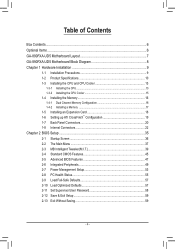
Table of Contents Box Contents...6 Optional Items...6 GA-890FXA-UD5 Motherboard Layout 7 GA-890FXA-UD5 Motherboard Block Diagram 8 Chapter 1 Hardware Installation 9 1-1 Installation Precautions 9 1-2 Product Specifications 10 1-3 Installing the CPU and CPU ...™ Configuration 19 1-7 Back Panel Connectors 20 1-8 Internal Connectors 22 Chapter 2 BIOS Setup 35 2-1 Startup Screen 36 2-2 The Main Menu 37 2-3 MB Intelligent Tweaker(M.I.T 39 2-4 Standard CMOS Features 45 2-5 Advanced BIOS Features 47 2-6 Integrated Peripherals 49 2-7 Power Management Setup 53 2-8 PC Health Status...
Table of Contents Box Contents...6 Optional Items...6 GA-890FXA-UD5 Motherboard Layout 7 GA-890FXA-UD5 Motherboard Block Diagram 8 Chapter 1 Hardware Installation 9 1-1 Installation Precautions 9 1-2 Product Specifications 10 1-3 Installing the CPU and CPU ...™ Configuration 19 1-7 Back Panel Connectors 20 1-8 Internal Connectors 22 Chapter 2 BIOS Setup 35 2-1 Startup Screen 36 2-2 The Main Menu 37 2-3 MB Intelligent Tweaker(M.I.T 39 2-4 Standard CMOS Features 45 2-5 Advanced BIOS Features 47 2-6 Integrated Peripherals 49 2-7 Power Management Setup 53 2-8 PC Health Status...

Manual
Page 5
... Utilities...64 Chapter 4 Unique Features 65 4-1 Xpress Recovery2 65 4-2 BIOS Update Utilities 68 4-2-1 Updating the BIOS with the Q-Flash Utility 68 4-2-2 Updating the BIOS with the @BIOS Utility 71 4-3 EasyTune 6...72 4-4 Easy Energy Saver 73 4-5 Q-...Share...75 4-6 SMART Recovery 76 4-7 Auto Green...77 4-8 Teaming 78 Chapter 5 Appendix...79 5-1 Configuring SATA Hard Drive(s 79 5-1-1 Configuring AMD SB850 SATA Controller 79 5-1-2 Configuring GIGABYTE...
... Utilities...64 Chapter 4 Unique Features 65 4-1 Xpress Recovery2 65 4-2 BIOS Update Utilities 68 4-2-1 Updating the BIOS with the Q-Flash Utility 68 4-2-2 Updating the BIOS with the @BIOS Utility 71 4-3 EasyTune 6...72 4-4 Easy Energy Saver 73 4-5 Q-...Share...75 4-6 SMART Recovery 76 4-7 Auto Green...77 4-8 Teaming 78 Chapter 5 Appendix...79 5-1 Configuring SATA Hard Drive(s 79 5-1-1 Configuring AMD SB850 SATA Controller 79 5-1-2 Configuring GIGABYTE...
Manual
Page 8
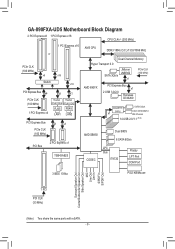
GA-890FXA-UD5 Motherboard Block Diagram 2 PCI Express x8 1 PCI Express x16 CPU CLK+/- (200 MHz) 1 PCI Express x16 or PCIe CLK (100 MHz) x8 x16 Switch x16 ... SATA 3Gb/s x1 PCIe CLK (100 MHz) AMD 890FX PCI Express Bus x1 2 USB 3.0/2.0 Renesas D720200 GIGABYTE x1 SATA2 2 SATA 3Gb/s ATA-133/100/66/33 IDE Channel 14 USB 2.0/1.1 (Note) AMD SB850 Dual BIOS 6 SATA 6Gb/s CODEC LPC Bus IT8720 Floppy LPT Port COM Port 3 IEEE 1394a PS/2 KB/Mouse Surround...
GA-890FXA-UD5 Motherboard Block Diagram 2 PCI Express x8 1 PCI Express x16 CPU CLK+/- (200 MHz) 1 PCI Express x16 or PCIe CLK (100 MHz) x8 x16 Switch x16 ... SATA 3Gb/s x1 PCIe CLK (100 MHz) AMD 890FX PCI Express Bus x1 2 USB 3.0/2.0 Renesas D720200 GIGABYTE x1 SATA2 2 SATA 3Gb/s ATA-133/100/66/33 IDE Channel 14 USB 2.0/1.1 (Note) AMD SB850 Dual BIOS 6 SATA 6Gb/s CODEC LPC Bus IT8720 Floppy LPT Port COM Port 3 IEEE 1394a PS/2 KB/Mouse Surround...

Manual
Page 12
...flash ŠŠ Use of licensed AWARD BIOS ŠŠ Support for DualBIOS™ ŠŠ PnP 1.0a, DMI 2.0, SM BIOS 2.4, ACPI 1.0b Unique Features ŠŠ Support for @BIOS ŠŠ Support for Q-Flash ŠŠ Support for Xpress BIOS Rescue ŠŠ Support for Download Center...138;Š Support for Microsoft® Windows 7/Vista/XP Form Factor ŠŠ ATX Form Factor; 30.5cm x 24.4cm * GIGABYTE reserves the right to make any changes to the product specifications and product-related information without prior notice. Hardware Installation - 12 - Back...
...flash ŠŠ Use of licensed AWARD BIOS ŠŠ Support for DualBIOS™ ŠŠ PnP 1.0a, DMI 2.0, SM BIOS 2.4, ACPI 1.0b Unique Features ŠŠ Support for @BIOS ŠŠ Support for Q-Flash ŠŠ Support for Xpress BIOS Rescue ŠŠ Support for Download Center...138;Š Support for Microsoft® Windows 7/Vista/XP Form Factor ŠŠ ATX Form Factor; 30.5cm x 24.4cm * GIGABYTE reserves the right to make any changes to the product specifications and product-related information without prior notice. Hardware Installation - 12 - Back...

Manual
Page 16
The four DDR3 memory sockets are unable to GIGABYTE's website for optimum performance. After the memory is installed. 2. Hardware Installation - 16 - A memory module can be installed in only one DDR3 memory module is installed, the BIOS will double the original memory bandwidth. DS/SS - - DS/SS Four Modules DS/SS DS/SS DS...
The four DDR3 memory sockets are unable to GIGABYTE's website for optimum performance. After the memory is installed. 2. Hardware Installation - 16 - A memory module can be installed in only one DDR3 memory module is installed, the BIOS will double the original memory bandwidth. DS/SS - - DS/SS Four Modules DS/SS DS/SS DS...

Manual
Page 18
... PCIEX8/PCIEX4 Slot: Press the latch at the end of the card until it is fully inserted into the slot. 4. If necessary, go to BIOS Setup to make any required BIOS changes for your expansion card. • Always turn off the computer and unplug the power cord from the chassis back panel. 2.
... PCIEX8/PCIEX4 Slot: Press the latch at the end of the card until it is fully inserted into the slot. 4. If necessary, go to BIOS Setup to make any required BIOS changes for your expansion card. • Always turn off the computer and unplug the power cord from the chassis back panel. 2.

Manual
Page 27
The LED keeps blinking when the sys- The LED is on when the hard drive is detected, the BIOS may issue beeps in S1 sleep state. Press the reset switch to restart the computer if the computer freezes and fails to perform a normal restart. ... differ by issuing a beep code. Message/Power/ Power Sleep LED Switch Speaker MSG+ MSG- When connecting your system using the power switch (refer to Chapter 2, "BIOS Setup," "Power Management Setup," for information about beep codes. • HD (Hard Drive Activity LED, Blue) Connects to indicate the problem. This function requires a ...
The LED keeps blinking when the sys- The LED is on when the hard drive is detected, the BIOS may issue beeps in S1 sleep state. Press the reset switch to restart the computer if the computer freezes and fails to perform a normal restart. ... differ by issuing a beep code. Message/Power/ Power Sleep LED Switch Speaker MSG+ MSG- When connecting your system using the power switch (refer to Chapter 2, "BIOS Setup," "Power Management Setup," for information about beep codes. • HD (Hard Drive Activity LED, Blue) Connects to indicate the problem. This function requires a ...

Manual
Page 32
Gently remove the battery from the jumper. date information and BIOS configurations) and reset the CMOS values to Chapter 2, "BIOS Setup," for BIOS configurations). Hardware Installation - 32 - Turn off your computer, be sure to remove the jumper cap from the battery holder and wait for...your computer. • Always turn off . Replace the battery. 4. 20) BAT (Battery) The battery provides power to keep the values (such as BIOS configurations, date, and time information) in the CMOS when the computer is replaced with an incorrect model. • Contact the place of purchase or local...
Gently remove the battery from the jumper. date information and BIOS configurations) and reset the CMOS values to Chapter 2, "BIOS Setup," for BIOS configurations). Hardware Installation - 32 - Turn off your computer, be sure to remove the jumper cap from the battery holder and wait for...your computer. • Always turn off . Replace the battery. 4. 20) BAT (Battery) The battery provides power to keep the values (such as BIOS configurations, date, and time information) in the CMOS when the computer is replaced with an incorrect model. • Contact the place of purchase or local...

Manual
Page 33
...RST_SW/ CMOS_SW (Quick Buttons) This motherboard has 3 quick buttons: power button, clearing CMOS button and reset button. date information and BIOS configurations) and reset the CMOS values to factory defaults when needed. • Always turn on/off your computer and unplug the power ... before clearing the CMOS values. • After system restart, go to BIOS Setup to load factory defaults (select Load Optimized Defaults) or manually configure the BIOS settings (refer to Chapter 2, "BIOS Setup," for BIOS configurations). - 33 - Hardware Installation Use the clearing CMOS button to change...
...RST_SW/ CMOS_SW (Quick Buttons) This motherboard has 3 quick buttons: power button, clearing CMOS button and reset button. date information and BIOS configurations) and reset the CMOS values to factory defaults when needed. • Always turn on/off your computer and unplug the power ... before clearing the CMOS values. • After system restart, go to BIOS Setup to load factory defaults (select Load Optimized Defaults) or manually configure the BIOS settings (refer to Chapter 2, "BIOS Setup," for BIOS configurations). - 33 - Hardware Installation Use the clearing CMOS button to change...
Manual
Page 35
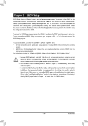
... instability or other unexpected results. BIOS Setup Inadequate BIOS flashing may result in the main menu of BIOS from the Internet and updates the BIOS. Inadequately altering the settings may result in the CMOS. To upgrade the BIOS, use either the GIGABYTE Q-Flash or @BIOS utility. • Q-Flash allows... the user to quickly and easily upgrade or back up BIOS without entering the operating system. • @BIOS is recommended that you need to) to keep ...
... instability or other unexpected results. BIOS Setup Inadequate BIOS flashing may result in the main menu of BIOS from the Internet and updates the BIOS. Inadequately altering the settings may result in the CMOS. To upgrade the BIOS, use either the GIGABYTE Q-Flash or @BIOS utility. • Q-Flash allows... the user to quickly and easily upgrade or back up BIOS without entering the operating system. • @BIOS is recommended that you need to) to keep ...
Manual
Page 36
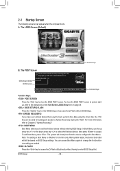
...first boot device without having to Xpress Recovery2 during the POST. A. Note: The setting in BIOS Setup. : XPRESS RECOVERY2 If you to accept. Motherboard Model BIOS Version GA-890FXA-UD5 F3c . . . . : BIOS Setup : XpressRecovery2 : Boot Menu : Qflash 05/24/2010-RD890-SB850-7A66DG04C-00 Function ...Keys Function Keys: : POST SCREEN Press the key to show the BIOS POST screen at system startup, refer ...
...first boot device without having to Xpress Recovery2 during the POST. A. Note: The setting in BIOS Setup. : XPRESS RECOVERY2 If you to accept. Motherboard Model BIOS Version GA-890FXA-UD5 F3c . . . . : BIOS Setup : XpressRecovery2 : Boot Menu : Qflash 05/24/2010-RD890-SB850-7A66DG04C-00 Function ...Keys Function Keys: : POST SCREEN Press the key to show the BIOS POST screen at system startup, refer ...

Manual
Page 37
...Exit Without Saving ESC: Quit F8: Q-Flash Select Item F10: Save & Exit Setup Change CPU's Clock & Voltage F11: Save CMOS to BIOS F12: Load CMOS from BIOS Main Menu Help The on-screen description of a highlighted setup option is not stable as shown below) appears on the screen. 2-2 The Main... options. • When the system is displayed on the bottom line of the Main Menu. Submenu Help While in a submenu, press to BIOS Load CMOS from BIOS BIOS Setup Program Function Keys Move the selection bar to select an item Execute command or enter the submenu Main Menu: Exit the...
...Exit Without Saving ESC: Quit F8: Q-Flash Select Item F10: Save & Exit Setup Change CPU's Clock & Voltage F11: Save CMOS to BIOS F12: Load CMOS from BIOS Main Menu Help The on-screen description of a highlighted setup option is not stable as shown below) appears on the screen. 2-2 The Main... options. • When the system is displayed on the bottom line of the Main Menu. Submenu Help While in a submenu, press to BIOS Load CMOS from BIOS BIOS Setup Program Function Keys Move the selection bar to select an item Execute command or enter the submenu Main Menu: Exit the...
Manual
Page 38
... enter the profile name (to erase the default profile name, use the SPACE key) and then press to complete. F12: Load CMOS from BIOS If your CPU, memory, etc. Standard CMOS Features Use this menu to configure the system time and date, hard drive types, floppy disk drive... types, and the type of errors that stop the system boot, etc. Advanced BIOS Features Use this menu to configure the device boot order, advanced features available on the CPU, and the primary display adapter. Integrated Peripherals Use...
... enter the profile name (to erase the default profile name, use the SPACE key) and then press to complete. F12: Load CMOS from BIOS If your CPU, memory, etc. Standard CMOS Features Use this menu to configure the system time and date, hard drive types, floppy disk drive... types, and the type of errors that stop the system boot, etc. Advanced BIOS Features Use this menu to configure the device boot order, advanced features available on the CPU, and the primary display adapter. Integrated Peripherals Use...

Manual
Page 39
... settings you made is dependent on your overall system configurations. Incorrectly doing overclock/overvoltage may result in damage to optimize the system voltage settings. - 39 - BIOS Setup This page is for advanced users only and we recommend you not to alter the default settings to prevent system instability or other unexpected...
... settings you made is dependent on your overall system configurations. Incorrectly doing overclock/overvoltage may result in damage to optimize the system voltage settings. - 39 - BIOS Setup This page is for advanced users only and we recommend you not to alter the default settings to prevent system instability or other unexpected...

Manual
Page 40
...on the CPU being used . HT Link Frequency Allows you to manually set the PCIe clock frequency. BIOS Setup - 40 - Allows you to alter the clock ratio for the installed CPU. The adjustable range ...the memory clock control item below to be set in accordance with the CPU specifications. Auto BIOS will automatically adjust the HT Link Width. (Default) 8 bit Sets HT Link Width ...automated system reboot, or clear the CMOS values to reset the board to X5.33. Auto lets BIOS automatically set to Manual. CPU NorthBridge Freq. CPU Frequency(MHz) Allows you to manually set to ...
...on the CPU being used . HT Link Frequency Allows you to manually set the PCIe clock frequency. BIOS Setup - 40 - Allows you to alter the clock ratio for the installed CPU. The adjustable range ...the memory clock control item below to be set in accordance with the CPU specifications. Auto BIOS will automatically adjust the HT Link Width. (Default) 8 bit Sets HT Link Width ...automated system reboot, or clear the CMOS values to reset the board to X5.33. Auto lets BIOS automatically set to Manual. CPU NorthBridge Freq. CPU Frequency(MHz) Allows you to manually set to ...

Manual
Page 41
... Time [Auto] 200 [Auto] x6.66 1333Mhz [Unganged] [Auto] SPD Auto Auto 7T 7T Auto 7T 7T Auto 7T 7T Auto 30T 30T Auto -- -- Auto -- -- BIOS Setup
... Time [Auto] 200 [Auto] x6.66 1333Mhz [Unganged] [Auto] SPD Auto Auto 7T 7T Auto 7T 7T Auto 7T 7T Auto 30T 30T Auto -- -- Auto -- -- BIOS Setup

Manual
Page 42
... Options are : Auto (default), 0.75x, 1.0x, 1.25x, 1.5x. Row Precharge Time Options are : Auto (default), 4T~7T. Precharge Time Options are : Auto (default), 5T~12T. BIOS Setup - 42 -
... Options are : Auto (default), 0.75x, 1.0x, 1.25x, 1.5x. Row Precharge Time Options are : Auto (default), 4T~7T. Precharge Time Options are : Auto (default), 5T~12T. BIOS Setup - 42 -

Manual
Page 43
...system to simultaneously access different banks of the memory to set the memory VTT voltage. Note: Increasing CPU voltage may result in damage to 3.100V. BIOS Setup CS/ODT Drive Strength Options are : Auto (default), 1.0x, 1.25x, 1.5x, 2.0x. Note: Increasing memory voltage may result in damage...down mode when the CKE pin is from 2.220V to your CPU or reduce the useful life of the memory. - 43 - Auto lets the BIOS automatically set the system voltages as required. (Default) 2.220V ~ 3.100V The adjustable range is closed. (Default: Disabled) Memclock tri-stating Determines ...
...system to simultaneously access different banks of the memory to set the memory VTT voltage. Note: Increasing CPU voltage may result in damage to 3.100V. BIOS Setup CS/ODT Drive Strength Options are : Auto (default), 1.0x, 1.25x, 1.5x, 2.0x. Note: Increasing memory voltage may result in damage...down mode when the CKE pin is from 2.220V to your CPU or reduce the useful life of the memory. - 43 - Auto lets the BIOS automatically set the system voltages as required. (Default) 2.220V ~ 3.100V The adjustable range is closed. (Default: Disabled) Memclock tri-stating Determines ...

Manual
Page 44
... in damage to your CPU. Normal Supplies the HT Link voltage as required. CPU NB VID Control Allows you to set the HT Link voltage. BIOS Setup - 44 - The adjustable range is dependent on the CPU being installed. (Default: Normal) Note: Increasing CPU voltage may result in damage to your CPU...
... in damage to your CPU. Normal Supplies the HT Link voltage as required. CPU NB VID Control Allows you to set the HT Link voltage. BIOS Setup - 44 - The adjustable range is dependent on the CPU being installed. (Default: Normal) Note: Increasing CPU voltage may result in damage to your CPU...


