Manual
Page 4
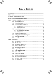
...890FXA-UD5 Motherboard Layout 7 GA-890FXA-UD5 Motherboard Block Diagram 8 Chapter 1 Hardware Installation 9 1-1 Installation Precautions 9 1-2 Product Specifications 10 1-3 Installing the CPU and CPU Cooler 13 1-3-1 Installing the CPU 13 1-3-2 Installing the CPU Cooler 15 1-4 Installing the Memory 16 1-4-1 Dual Channel Memory Configuration 16 1-4-2 Installing a Memory 17 1-5 Installing an Expansion Card 18 1-6 Setting up ATI CrossFireX™ Configuration 19 1-7 Back Panel Connectors 20 1-8 Internal Connectors 22 Chapter 2 BIOS Setup 35 2-1 Startup Screen 36 2-2 The Main Menu...
...890FXA-UD5 Motherboard Layout 7 GA-890FXA-UD5 Motherboard Block Diagram 8 Chapter 1 Hardware Installation 9 1-1 Installation Precautions 9 1-2 Product Specifications 10 1-3 Installing the CPU and CPU Cooler 13 1-3-1 Installing the CPU 13 1-3-2 Installing the CPU Cooler 15 1-4 Installing the Memory 16 1-4-1 Dual Channel Memory Configuration 16 1-4-2 Installing a Memory 17 1-5 Installing an Expansion Card 18 1-6 Setting up ATI CrossFireX™ Configuration 19 1-7 Back Panel Connectors 20 1-8 Internal Connectors 22 Chapter 2 BIOS Setup 35 2-1 Startup Screen 36 2-2 The Main Menu...
Manual
Page 19
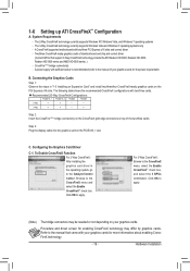
... manual that support 3-Way CrossFireX technology include the ATI Radeon HD 3800, Radeon HD 4800, Radeon HD 5800 series and AMD HD 6900 series .) - The 3-Way CrossFireX technology currently supports Windows Vista and Windows 7 operating systems only - The following table shows the recommended CrossFireX configurations with two/three PCI Express x16 slots and correct driver - Recommended 2/3-Way CrossFireX Configurations: PCIEX16_1 PCIEX16_2 PCIEX4 PCIEX8 2-Way a a - - - - 3-Way a a - - Connecting the Graphics Cards...
... manual that support 3-Way CrossFireX technology include the ATI Radeon HD 3800, Radeon HD 4800, Radeon HD 5800 series and AMD HD 6900 series .) - The 3-Way CrossFireX technology currently supports Windows Vista and Windows 7 operating systems only - The following table shows the recommended CrossFireX configurations with two/three PCI Express x16 slots and correct driver - Recommended 2/3-Way CrossFireX Configurations: PCIEX16_1 PCIEX16_2 PCIEX4 PCIEX8 2-Way a a - - - - 3-Way a a - - Connecting the Graphics Cards...

Manual
Page 24
... (Fan Headers) The motherboard has a 4-pin CPU fan header (CPU_FAN), a 4-pin (SYS_FAN1) and a 3-pin (SYS_ FAN2) system fan headers, and a 3-pin power fan header (PWR_FAN). When connecting a fan cable, be installed inside the chassis. The black connector wire is recom- Do not place a jumper cap on the headers. The motherboard supports CPU fan speed control, which requires the use of a CPU fan with color-coded power connector wires. Definition 1 1 GND CPU_FAN 2 +12V / Speed Control 3 Sense 4 Speed Control SYS_FAN1: Pin No. Most fans are not configuration jumper blocks...
... (Fan Headers) The motherboard has a 4-pin CPU fan header (CPU_FAN), a 4-pin (SYS_FAN1) and a 3-pin (SYS_ FAN2) system fan headers, and a 3-pin power fan header (PWR_FAN). When connecting a fan cable, be installed inside the chassis. The black connector wire is recom- Do not place a jumper cap on the headers. The motherboard supports CPU fan speed control, which requires the use of a CPU fan with color-coded power connector wires. Definition 1 1 GND CPU_FAN 2 +12V / Speed Control 3 Sense 4 Speed Control SYS_FAN1: Pin No. Most fans are not configuration jumper blocks...

Manual
Page 33
... BIOS Setup to load factory defaults (select Load Optimized Defaults) or manually configure the BIOS settings (refer to clear the CMOS values (e.g. Hardware Installation Use the clearing CMOS button to Chapter 2, "BIOS Setup," for BIOS configurations). - 33 - The power button and reset button allow users to quickly turn off or reset the computer in an open-case environment when they want to change hardware components or conduct hardware testing. 22/23/24) PW_SW/ RST_SW/ CMOS_SW (Quick Buttons) This motherboard has 3 quick buttons: power button, clearing CMOS button and reset button...
... BIOS Setup to load factory defaults (select Load Optimized Defaults) or manually configure the BIOS settings (refer to clear the CMOS values (e.g. Hardware Installation Use the clearing CMOS button to Chapter 2, "BIOS Setup," for BIOS configurations). - 33 - The power button and reset button allow users to quickly turn off or reset the computer in an open-case environment when they want to change hardware components or conduct hardware testing. 22/23/24) PW_SW/ RST_SW/ CMOS_SW (Quick Buttons) This motherboard has 3 quick buttons: power button, clearing CMOS button and reset button...
Manual
Page 35
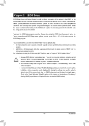
... problems using the Q-Flash and @BIOS utilities, refer to Chapter 4, "BIOS Update Utilities." • Because BIOS flashing is potentially risky, if you do it is recommended that you not flash the BIOS. If this occurs, try to clear the CMOS values and reset the board to default values. (Refer to the "Load Optimized Defaults" section in this chapter or introductions of the battery/ clearing CMOS jumper/button in system's failure to boot. For instructions on the motherboard. BIOS Setup Chapter 2 BIOS Setup BIOS...
... problems using the Q-Flash and @BIOS utilities, refer to Chapter 4, "BIOS Update Utilities." • Because BIOS flashing is potentially risky, if you do it is recommended that you not flash the BIOS. If this occurs, try to clear the CMOS values and reset the board to default values. (Refer to the "Load Optimized Defaults" section in this chapter or introductions of the battery/ clearing CMOS jumper/button in system's failure to boot. For instructions on the motherboard. BIOS Setup Chapter 2 BIOS Setup BIOS...
Manual
Page 36
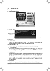
... hard drive data using the driver disk, the key can access Boot Menu again to change the first boot device setting as needed. : Q-FLASH Press the key to access the Q-Flash utility directly without entering BIOS Setup. The system will still be used for one time only. After system restart, the device boot order will directly boot from the device configured in Boot Menu is effective for subsequent access to the instructions on the Full Screen LOGO Show item on BIOS Setup settings. Motherboard Model BIOS Version GA-890FXA-UD5 F3c . . . . : BIOS Setup : XpressRecovery2 : Boot...
... hard drive data using the driver disk, the key can access Boot Menu again to change the first boot device setting as needed. : Q-FLASH Press the key to access the Q-Flash utility directly without entering BIOS Setup. The system will still be used for one time only. After system restart, the device boot order will directly boot from the device configured in Boot Menu is effective for subsequent access to the instructions on the Full Screen LOGO Show item on BIOS Setup settings. Motherboard Model BIOS Version GA-890FXA-UD5 F3c . . . . : BIOS Setup : XpressRecovery2 : Boot...
Manual
Page 38
... CPU, memory, etc. Standard CMOS Features Use this menu to configure the system time and date, hard drive types, floppy disk drive types, and the type of errors that stop the system boot, etc. Advanced BIOS Features Use this menu to configure the device boot order, advanced features available on the CPU, and the primary display adapter. Integrated Peripherals Use this menu to configure all peripheral devices, such as IDE, SATA, USB, integrated audio, and integrated LAN, etc. Power Management Setup Use...
... CPU, memory, etc. Standard CMOS Features Use this menu to configure the system time and date, hard drive types, floppy disk drive types, and the type of errors that stop the system boot, etc. Advanced BIOS Features Use this menu to configure the device boot order, advanced features available on the CPU, and the primary display adapter. Integrated Peripherals Use this menu to configure all peripheral devices, such as IDE, SATA, USB, integrated audio, and integrated LAN, etc. Power Management Setup Use...

Manual
Page 40
... is highly recommended that the CPU frequency be configurable. (Default: Auto) Memory Clock This option is configurable only when Set Memory Clock is dependent on the CPU being used . PCIE Clock(MHz) Allows you to manually set in accordance with the CPU specifications. HT Link Frequency Allows you to manually set the PCIe clock frequency. Set Memory Clock Determines whether to manually set the width for the HT Link between the CPU and chipset. X5.33 Sets Memory Clock to 16 bit. CPU Host Clock Control Enables or disables the control of CPU host clock. Auto BIOS will...
... is highly recommended that the CPU frequency be configurable. (Default: Auto) Memory Clock This option is configurable only when Set Memory Clock is dependent on the CPU being used . PCIE Clock(MHz) Allows you to manually set in accordance with the CPU specifications. HT Link Frequency Allows you to manually set the PCIe clock frequency. Set Memory Clock Determines whether to manually set the width for the HT Link between the CPU and chipset. X5.33 Sets Memory Clock to 16 bit. CPU Host Clock Control Enables or disables the control of CPU host clock. Auto BIOS will...

Manual
Page 43
...set the memory to power down mode when the CKE pin is from 2.220V to set memory voltage. Note: Increasing memory voltage may result in CPU C3 or Alt VID mode. (Default: Disabled) ******** System Voltage Optimized ******** System Voltage Control Determines whether to increase memory performance and stability. (Default: Enabled) Channel interleave Enables or disables memory channel interleaving. Bank Interleaving Enables or disables memory bank interleaving. DRAM Voltage Control Allows you to 1.050V. DDR VTT Voltage Control Allows you to 2.410V. Normal Supplies the memory...
...set the memory to power down mode when the CKE pin is from 2.220V to set memory voltage. Note: Increasing memory voltage may result in CPU C3 or Alt VID mode. (Default: Disabled) ******** System Voltage Optimized ******** System Voltage Control Determines whether to increase memory performance and stability. (Default: Enabled) Channel interleave Enables or disables memory channel interleaving. Bank Interleaving Enables or disables memory bank interleaving. DRAM Voltage Control Allows you to 1.050V. DDR VTT Voltage Control Allows you to 2.410V. Normal Supplies the memory...

Manual
Page 47
... HDD Init Display First [Auto] [Disabled] [Auto] [Disabled] [Auto] Enabled Enabled Enabled [Press Enter] [Hard Disk] [CDROM] [Floppy] [Setup] [Disabled] [Disabled] [Enabled] [Disabled] [PCI Slot] Item Help Menu Level Move Enter: Select F5: Previous Values +/-/PU/PD: Value F10: Save F6: Fail-Safe Defaults ESC: Exit F1: General Help F7: Optimized Defaults AMD C1E Support (Note) Enables or disables the C1E CPU power-saving function in independent partitions. 2-5 Advanced BIOS Features CMOS Setup Utility-Copyright (C) 1984-2009 Award Software Advanced BIOS Features...
... HDD Init Display First [Auto] [Disabled] [Auto] [Disabled] [Auto] Enabled Enabled Enabled [Press Enter] [Hard Disk] [CDROM] [Floppy] [Setup] [Disabled] [Disabled] [Enabled] [Disabled] [PCI Slot] Item Help Menu Level Move Enter: Select F5: Previous Values +/-/PU/PD: Value F10: Save F6: Fail-Safe Defaults ESC: Exit F1: General Help F7: Optimized Defaults AMD C1E Support (Note) Enables or disables the C1E CPU power-saving function in independent partitions. 2-5 Advanced BIOS Features CMOS Setup Utility-Copyright (C) 1984-2009 Award Software Advanced BIOS Features...

Manual
Page 48
... minus key (or ) to move it will be recovered from the installed hard drives. First/Second/Third Boot Device Specifies the boot order from the installed PCI graphics card or the PCI Express graphics card. This feature allows your hard drive. Options are: Floppy, LS120, Hard Disk, CDROM, ZIP, USB-FDD, USB-ZIP, USB-CDROM, USB-HDD, Legacy LAN, Disabled. After configuring this item, set the password(s) under the Set Supervisor/User Password item in a low-power mode that appears off. (Default: Disabled) Full Screen LOGO Show Allows you enter BIOS Setup. Away Mode...
... minus key (or ) to move it will be recovered from the installed hard drives. First/Second/Third Boot Device Specifies the boot order from the installed PCI graphics card or the PCI Express graphics card. This feature allows your hard drive. Options are: Floppy, LS120, Hard Disk, CDROM, ZIP, USB-FDD, USB-ZIP, USB-CDROM, USB-HDD, Legacy LAN, Disabled. After configuring this item, set the password(s) under the Set Supervisor/User Password item in a low-power mode that appears off. (Default: Disabled) Full Screen LOGO Show Allows you enter BIOS Setup. Away Mode...

Manual
Page 49
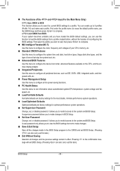
... hot plug. - 49 - 2-6 Integrated Peripherals CMOS Setup Utility-Copyright (C) 1984-2010 Award Software Integrated Peripherals OnChip SATA Controller OnChip SATA Type x OnChip SATA Port4/5 Type x OnChip SATA RAID5 Support OnChip SATA3.0 Support Onboard GSATA/IDE Ctrl Onboard GSATA/IDE Mode Onboard ESATA controller Onboard ESATA Mode Green LAN Onboard LAN1 Function Onboard LAN1 Boot ROM } SMART LAN1 Onboard LAN2 Function Onboard LAN2 Boot ROM } SMART LAN2 Onboard Audio Function Onboard 1394 Function Onboard USB 3.0 Controller [Enabled] [Native IDE] IDE...
... hot plug. - 49 - 2-6 Integrated Peripherals CMOS Setup Utility-Copyright (C) 1984-2010 Award Software Integrated Peripherals OnChip SATA Controller OnChip SATA Type x OnChip SATA Port4/5 Type x OnChip SATA RAID5 Support OnChip SATA3.0 Support Onboard GSATA/IDE Ctrl Onboard GSATA/IDE Mode Onboard ESATA controller Onboard ESATA Mode Green LAN Onboard LAN1 Function Onboard LAN1 Boot ROM } SMART LAN1 Onboard LAN2 Function Onboard LAN2 Boot ROM } SMART LAN2 Onboard Audio Function Onboard 1394 Function Onboard USB 3.0 Controller [Enabled] [Native IDE] IDE...
Manual
Page 50
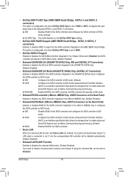
...SATA Type is set to RAID or AHCI. OnChip SATA3.0 Support Enables or disables the SATA 6Gb/s function integrated in IDE mode. IDE Configures the SATA controller to IDE mode. (Default) AHCI Configures the SATA controller to AHCI mode. BIOS Setup - 50 - Configures the operating mode of using the onboard LAN, set this item to Disabled. Green LAN When the onboard LAN function and Green LAN are enabled, the system will dynamically detect if a LAN cable is connected or not. OnChip SATA Port4/5 Type (AMD SB850 South Bridge, SATA3_4 and SATA3_5 connectors) This option is configurable...
...SATA Type is set to RAID or AHCI. OnChip SATA3.0 Support Enables or disables the SATA 6Gb/s function integrated in IDE mode. IDE Configures the SATA controller to IDE mode. (Default) AHCI Configures the SATA controller to AHCI mode. BIOS Setup - 50 - Configures the operating mode of using the onboard LAN, set this item to Disabled. Green LAN When the onboard LAN function and Green LAN are enabled, the system will dynamically detect if a LAN cable is connected or not. OnChip SATA Port4/5 Type (AMD SB850 South Bridge, SATA3_4 and SATA3_5 connectors) This option is configurable...

Manual
Page 52
... Enabled) USB Controllers Enables or disables the integrated USB controllers. (Default: Enabled) Disabled will turn off all of using the onboard audio, set to ECP or ECP+EPP mode. This item is configurable only if Parallel Port Mode is set this item to Disabled. Options are : 378/IRQ7 (default), 278/IRQ5, 3BC/IRQ7, Disabled. Parallel Port Mode Selects an operating mode for the LPT port in MS-DOS. (Default: Enabled) USB Storage Function Determines whether to detect USB storage devices, including USB flash drives and USB hard drives during the POST. (Default: Enabled) Onboard Serial Port...
... Enabled) USB Controllers Enables or disables the integrated USB controllers. (Default: Enabled) Disabled will turn off all of using the onboard audio, set to ECP or ECP+EPP mode. This item is configurable only if Parallel Port Mode is set this item to Disabled. Options are : 378/IRQ7 (default), 278/IRQ5, 3BC/IRQ7, Disabled. Parallel Port Mode Selects an operating mode for the LPT port in MS-DOS. (Default: Enabled) USB Storage Function Determines whether to detect USB storage devices, including USB flash drives and USB hard drives during the POST. (Default: Enabled) Onboard Serial Port...

Manual
Page 53
... resumes to enter the ACPI S1 (Power on Windows 7/Vista operating system only. - 53 - S1(POS) Enables the system to its working state exactly where it was left off the system. Press and hold the power button for less than in a low power mode. BIOS Setup 2-7 Power Management Setup CMOS Setup Utility-Copyright (C) 1984-2010 Award Software Power Management Setup ACPI Suspend Type Soft-Off by Power button USB Wake Up from a PCI or PCIe device. In S1 sleep state, the...
... resumes to enter the ACPI S1 (Power on Windows 7/Vista operating system only. - 53 - S1(POS) Enables the system to its working state exactly where it was left off the system. Press and hold the power button for less than in a low power mode. BIOS Setup 2-7 Power Management Setup CMOS Setup Utility-Copyright (C) 1984-2010 Award Software Power Management Setup ACPI Suspend Type Soft-Off by Power button USB Wake Up from a PCI or PCIe device. In S1 sleep state, the...

Manual
Page 80
... BIOS Setup. CMOS Setup Utility-Copyright (C) 1984-2010 Award Software Integrated Peripherals OnChip SATA Controller OnChip SATA Type OnChip SATA Port4/5 Type OnChip SATA RAID5 Support OnChip SATA3.0 Support Onboard GSATA/IDE Ctrl Onboard GSATA/IDE Mode Onboard ESATA controller Onboard ESATA Mode Green LAN Onboard LAN1 Function Onboard LAN1 Boot ROM } SMART LAN1 Onboard LAN2 Function Onboard LAN2 Boot ROM } SMART LAN2 Onboard Audio Function Onboard 1394 Function Onboard USB 3.0 Controller [Enabled] [RAID] [As SATA Type] [Enabled] [Enabled] [Enabled...
... BIOS Setup. CMOS Setup Utility-Copyright (C) 1984-2010 Award Software Integrated Peripherals OnChip SATA Controller OnChip SATA Type OnChip SATA Port4/5 Type OnChip SATA RAID5 Support OnChip SATA3.0 Support Onboard GSATA/IDE Ctrl Onboard GSATA/IDE Mode Onboard ESATA controller Onboard ESATA Mode Green LAN Onboard LAN1 Function Onboard LAN1 Boot ROM } SMART LAN1 Onboard LAN2 Function Onboard LAN2 Boot ROM } SMART LAN2 Onboard Audio Function Onboard 1394 Function Onboard USB 3.0 Controller [Enabled] [RAID] [As SATA Type] [Enabled] [Enabled] [Enabled...

Manual
Page 85
...hard drive. Appendix In BIOS Setup, go to RAID CMOS Setup Utility-Copyright (C) 1984-2010 Award Software Integrated Peripherals OnChip SATA Controller OnChip SATA Type x OnChip SATA Port4/5 Type x OnChip SATA RAID5 Support OnChip SATA3.0 Support Onboard GSATA/IDE Ctrl Onboard GSATA/IDE Mode Onboard ESATA controller Onboard ESATA Mode Green LAN Onboard LAN1 Function Onboard LAN1 Boot ROM } SMART LAN1 Onboard LAN2 Function Onboard LAN2 Boot ROM } SMART LAN2 Onboard Audio Function Onboard 1394 Function Onboard USB 3.0 Controller [Enabled] [Native IDE...
...hard drive. Appendix In BIOS Setup, go to RAID CMOS Setup Utility-Copyright (C) 1984-2010 Award Software Integrated Peripherals OnChip SATA Controller OnChip SATA Type x OnChip SATA Port4/5 Type x OnChip SATA RAID5 Support OnChip SATA3.0 Support Onboard GSATA/IDE Ctrl Onboard GSATA/IDE Mode Onboard ESATA controller Onboard ESATA Mode Green LAN Onboard LAN1 Function Onboard LAN1 Boot ROM } SMART LAN1 Onboard LAN2 Function Onboard LAN2 Boot ROM } SMART LAN2 Onboard Audio Function Onboard 1394 Function Onboard USB 3.0 Controller [Enabled] [Native IDE...

Manual
Page 91
... installing Windows Vista, you need to install the SATA controller driver during the Windows setup process. Appendix sume that the drive letter for your optical drive is /are configured to RAID/AHCI mode, you also can copy the SATA controller driver from the motherboard driver disk to a USB flash drive. In MS-DOS mode: Prepare a startup disk that has CD-ROM support and a blank formatted floppy disk. Steps: 1: Boot from the startup disk. 2: Remove the startup disk and insert the prepared floppy disk and the motherboard driver disk...
... installing Windows Vista, you need to install the SATA controller driver during the Windows setup process. Appendix sume that the drive letter for your optical drive is /are configured to RAID/AHCI mode, you also can copy the SATA controller driver from the motherboard driver disk to a USB flash drive. In MS-DOS mode: Prepare a startup disk that has CD-ROM support and a blank formatted floppy disk. Steps: 1: Boot from the startup disk. 2: Remove the startup disk and insert the prepared floppy disk and the motherboard driver disk...

Manual
Page 94
... Adapter you can proceed with Windows, using a device support disk provided by an adapter manufacturer. After the driver installation, you want from the following list, or press ESC to return to configure a SCSI Adapter for GIGABYTE GBB36X Controller (x32) and press . Select RAID/AHCI Driver for use with the Windows XP installation. Appendix - 94 - Windows Setup You have chosen to the previous screen. RAID/AHCI Driver for GIGABYTE GBB36X Controller (x32) ENTER=Select F3=Exit Figure...
... Adapter you can proceed with Windows, using a device support disk provided by an adapter manufacturer. After the driver installation, you want from the following list, or press ESC to return to configure a SCSI Adapter for GIGABYTE GBB36X Controller (x32) and press . Select RAID/AHCI Driver for use with the Windows XP installation. Appendix - 94 - Windows Setup You have chosen to the previous screen. RAID/AHCI Driver for GIGABYTE GBB36X Controller (x32) ENTER=Select F3=Exit Figure...

Manual
Page 110
...internal amplifier. Then install the onboard HD audio driver from the motherboard driver disk or download the audio driver from the battery holder to stop supplying power to the CMOS, which will clear the CMOS values after the computer shuts down ? A: The following Award BIOS beep code descriptions may help you identify possible computer problems. (For reference only.) 1 short: System boots successfully 2 short: CMOS setting error 1 long, 9 short: BIOS ROM error 1 long, 1 short: Memory or motherboard error Continuous long beeps: Graphics card not inserted properly 1 long, 2 short...
...internal amplifier. Then install the onboard HD audio driver from the motherboard driver disk or download the audio driver from the battery holder to stop supplying power to the CMOS, which will clear the CMOS values after the computer shuts down ? A: The following Award BIOS beep code descriptions may help you identify possible computer problems. (For reference only.) 1 short: System boots successfully 2 short: CMOS setting error 1 long, 9 short: BIOS ROM error 1 long, 1 short: Memory or motherboard error Continuous long beeps: Graphics card not inserted properly 1 long, 2 short...


