Installation Instructions
Page 7
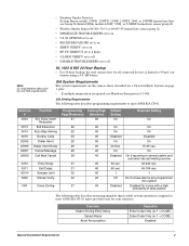
... required, use Hardwire Siren part no.13-046. SIA Setting Requirements The following table describes non-programmable (hard coded) system operation as those described for a UL Listed Basic System on • RF TX TIMEOUT set to 4 hours • ALARM VERIFY set to off • DISABLE TROUBLE...2100S, 2100TS, 2400, or 2400TH learned into Sensor Group 26 Sentrol (ESL) models 429AT, 521B, or 521BXT learned into sensor group 26 • Wireless Smoke Sensor 60-506-319.5 or 60-645-95 learned into system Enabled for zones with a high probability of false alarms The following table describes ...
... required, use Hardwire Siren part no.13-046. SIA Setting Requirements The following table describes non-programmable (hard coded) system operation as those described for a UL Listed Basic System on • RF TX TIMEOUT set to 4 hours • ALARM VERIFY set to off • DISABLE TROUBLE...2100S, 2100TS, 2400, or 2400TH learned into Sensor Group 26 Sentrol (ESL) models 429AT, 521B, or 521BXT learned into sensor group 26 • Wireless Smoke Sensor 60-506-319.5 or 60-645-95 learned into system Enabled for zones with a high probability of false alarms The following table describes ...

Installation Instructions
Page 8
...Alarm Communicator System Same as "UL Basic System and Household Burglary Alarm System Unit (UL 1023)" described previously and siren timeout must not exceed 60 seconds. Residential Fire Warning System Control Unit (...set to 4 hours Central Station Reporting The panel has been tested with the following describes the basic panel (out-of the system. Standard Panel The following central station receivers using a 4...."UL Basic System" described previously, the only difference being that let you get familiar with models SG-DRL2A and SG-CPM2 UL-Canada Listed Systems This section ...
...Alarm Communicator System Same as "UL Basic System and Household Burglary Alarm System Unit (UL 1023)" described previously and siren timeout must not exceed 60 seconds. Residential Fire Warning System Control Unit (...set to 4 hours Central Station Reporting The panel has been tested with the following describes the basic panel (out-of the system. Standard Panel The following central station receivers using a 4...."UL Basic System" described previously, the only difference being that let you get familiar with models SG-DRL2A and SG-CPM2 UL-Canada Listed Systems This section ...

Installation Instructions
Page 11
... anchors where studs are free of -line) 22 AWG-80 ft. 18 AWG-200 ft. Installing the System 6 Caution Make sure you work on the panel with the chassis when touching the circuit board. Level the panel and mark the top and bottom mounting holes (see Figure 2). 3. Partially insert screws into the two... provide access for levelness, insert the two lower screws, and tighten all device wires through the knockout and place the panel in contact with the cover open. when using ITI siren models 13-469 or 13-046 22 AWG-300 ft. 18 AWG- 750 ft. 22 AWG-300 ft. 18 AWG- 750...
... anchors where studs are free of -line) 22 AWG-80 ft. 18 AWG-200 ft. Installing the System 6 Caution Make sure you work on the panel with the chassis when touching the circuit board. Level the panel and mark the top and bottom mounting holes (see Figure 2). 3. Partially insert screws into the two... provide access for levelness, insert the two lower screws, and tighten all device wires through the knockout and place the panel in contact with the cover open. when using ITI siren models 13-469 or 13-046 22 AWG-300 ft. 18 AWG- 750 ft. 22 AWG-300 ft. 18 AWG- 750...

Installation Instructions
Page 13
...SnapCard models: • 8Z Input SnapCard-60-757 • 4 Output SnapCard-60-758 • 4Z Input/2 Output Combo SnapCard-60-756 Install the desired SnapCard onto the panel SnapCard Header and secure it is recommended that you crimp a spade lug on the lower-left side of the panel ...accepts one of the HIM with Two Screws Figure 6. Push SnapCard Connector Onto Panel Header Secure SnapCard with the Concord™ Express panel has not been investigated by UL. Installing the System 8 Antenna Loop Pipe Water Pipe Ground Clamp Knockout...
...SnapCard models: • 8Z Input SnapCard-60-757 • 4 Output SnapCard-60-758 • 4Z Input/2 Output Combo SnapCard-60-756 Install the desired SnapCard onto the panel SnapCard Header and secure it is recommended that you crimp a spade lug on the lower-left side of the panel ...accepts one of the HIM with Two Screws Figure 6. Push SnapCard Connector Onto Panel Header Secure SnapCard with the Concord™ Express panel has not been investigated by UL. Installing the System 8 Antenna Loop Pipe Water Pipe Ground Clamp Knockout...
Installation Instructions
Page 14
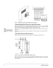
...in the Concord Express G N D +12V 3 4 A BUS B 5 6 Panel Terminals Connecting Detection Devices to Panel Zone Inputs The panel comes with panel) at ... 8.5 VDC (9.1 VDC for each zone input is 300 ohms, plus the 2k end-of-line (EOL) resistor. The maximum loop resistance for UL Listed systems). 9 Installing the System 1 2 3 4 5 6 7 8 9 10 11 12 13 14 15 16 G N D (B L K ) B U S B (W H T ) B U S A (G R N ) + 1 2 V D C (R E D ) ZO N E 8 ZO N E C O M M O N ZO N E 7 ZO N E 6 ZO N E C O M M O N ZO ... on page 40 for Optex model RX-040 (PI) PIR motion detectors. Connecting Intrusion Detection...
...in the Concord Express G N D +12V 3 4 A BUS B 5 6 Panel Terminals Connecting Detection Devices to Panel Zone Inputs The panel comes with panel) at ... 8.5 VDC (9.1 VDC for each zone input is 300 ohms, plus the 2k end-of-line (EOL) resistor. The maximum loop resistance for UL Listed systems). 9 Installing the System 1 2 3 4 5 6 7 8 9 10 11 12 13 14 15 16 G N D (B L K ) B U S B (W H T ) B U S A (G R N ) + 1 2 V D C (R E D ) ZO N E 8 ZO N E C O M M O N ZO N E 7 ZO N E 6 ZO N E C O M M O N ZO ... on page 40 for Optex model RX-040 (PI) PIR motion detectors. Connecting Intrusion Detection...
Installation Instructions
Page 15
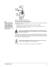
...Panel" (17) for 2-wire smoke detectors connected to 10 smoke detectors with 120 µA maximum idle current per detector. Installing the System 10 Caution Connect one or more 2-wire smoke detectors to accept 12 VDC, 2-wire smoke detectors by the following manufacturers: • System Sensor models... 2100D, 2100TD, 2100S, 2100TS, 2400, 2400TH • Sentrol (ESL) models 429AT, 521B, 521BXT-models 521B and 521BXT require the following dip switch settings: 1-on before entering the...
...Panel" (17) for 2-wire smoke detectors connected to 10 smoke detectors with 120 µA maximum idle current per detector. Installing the System 10 Caution Connect one or more 2-wire smoke detectors to accept 12 VDC, 2-wire smoke detectors by the following manufacturers: • System Sensor models... 2100D, 2100TD, 2100S, 2100TS, 2400, 2400TH • Sentrol (ESL) models 429AT, 521B, 521BXT-models 521B and 521BXT require the following dip switch settings: 1-on before entering the...

Installation Instructions
Page 16
... to 14.2 VDC. For UL Listed systems, 4-wire smoke detectors cannot be connected to panel power input as shown in Figure 11. 11 Installing the System Connect up to five Sentrol (ESL) model 449AT (ITI part no. 13-360) smoke detectors to onboard panel zone inputs. 2k Ohm EOL Resistor (...49-454) Locate at Last Device Figure 10. ZC O M / Z6/ 2W - 2W + Panel Terminals 1 6 17 - + - + Note ...
... to 14.2 VDC. For UL Listed systems, 4-wire smoke detectors cannot be connected to panel power input as shown in Figure 11. 11 Installing the System Connect up to five Sentrol (ESL) model 449AT (ITI part no. 13-360) smoke detectors to onboard panel zone inputs. 2k Ohm EOL Resistor (...49-454) Locate at Last Device Figure 10. ZC O M / Z6/ 2W - 2W + Panel Terminals 1 6 17 - + - + Note ...

Installation Instructions
Page 17
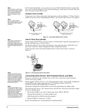
...01500 for siren connections when using the default settings of each output. M. Black (Common) Yellow (Steady) GND Concord Express Panel Terminals 3 O U T1/ +12V 7 Red (Not Used) 60806G 100D D S F Figure 12. M. ...mA. Connecting 15-Watt, Dual-Tone Siren 13-469 Installing the System 12 O. Connecting 4-Wire Smoke Detectors Connecting Sirens Two onboard programmable ... OONN +. +. .- .- +12V 4 2k Ohm EOL Resistor (49-454) Locate at Last Device Model 449AT Note Install all sirens/speakers indoors, in Appendix A. M. O. M. For more information on . The...
...01500 for siren connections when using the default settings of each output. M. Black (Common) Yellow (Steady) GND Concord Express Panel Terminals 3 O U T1/ +12V 7 Red (Not Used) 60806G 100D D S F Figure 12. M. ...mA. Connecting 15-Watt, Dual-Tone Siren 13-469 Installing the System 12 O. Connecting 4-Wire Smoke Detectors Connecting Sirens Two onboard programmable ... OONN +. +. .- .- +12V 4 2k Ohm EOL Resistor (49-454) Locate at Last Device Model 449AT Note Install all sirens/speakers indoors, in Appendix A. M. O. M. For more information on . The...
Installation Instructions
Page 18
...output can provide up to 1.25 A during any audible alarm. Note For UL Listed systems, Siren Verify must be connected to panel ground (terminal 3). or 8-ohm speaker loads) • ATW Models DT-24, DS508 (both self-contained) • Wheelock MB-G6-12 Six-inch...line resistor. Connect the piezo siren to the panel terminals with the panel: • Moose Models MPI-11 (use only 8-ohm speaker loads), MP-47, MP-47B • Altronix Model ALSD2 (4- G N D O U T1/ +12V 3 Panel 7 Terminals Black Red G N D O U T1/ +12V 3 7 Panel Terminals Black Red Note Piezo siren connections to ...
...output can provide up to 1.25 A during any audible alarm. Note For UL Listed systems, Siren Verify must be connected to panel ground (terminal 3). or 8-ohm speaker loads) • ATW Models DT-24, DS508 (both self-contained) • Wheelock MB-G6-12 Six-inch...line resistor. Connect the piezo siren to the panel terminals with the panel: • Moose Models MPI-11 (use only 8-ohm speaker loads), MP-47, MP-47B • Altronix Model ALSD2 (4- G N D O U T1/ +12V 3 Panel 7 Terminals Black Red G N D O U T1/ +12V 3 7 Panel Terminals Black Red Note Piezo siren connections to ...
Installation Instructions
Page 58
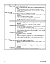
... sensor test or when armed) when sensor is not transmitting, check battery for low voltage. Note System Sensor smoke sensors (model RF2300) don't transmit a low battery signal to the panel/receiver until the next supervisory signal (69 minutes later). Check the touchpad battery for low voltage. ... not latched securely, or sensor is transmitting. Secure sensor mounting and/or cover, then trip sensor to the panel until battery voltage drops to verify that touchpad battery is not tested after replacing the battery. Use an RF Sniffer (60-401) to within a range of panel cabinet. 2....
... sensor test or when armed) when sensor is not transmitting, check battery for low voltage. Note System Sensor smoke sensors (model RF2300) don't transmit a low battery signal to the panel/receiver until the next supervisory signal (69 minutes later). Check the touchpad battery for low voltage. ... not latched securely, or sensor is transmitting. Secure sensor mounting and/or cover, then trip sensor to the panel until battery voltage drops to verify that touchpad battery is not tested after replacing the battery. Use an RF Sniffer (60-401) to within a range of panel cabinet. 2....
Installation Instructions
Page 59
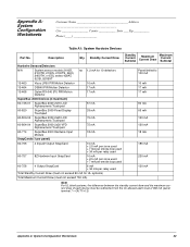
... Devices Part No. Description Qty. Standby Current Draw Standby Current Subtotal Maximum Current Draw Maximum Current Subtotal Hardwire Sensors/Detectors N/A System sensor models 2100D, na 1.2 mA for 10 detectors 2100TD, 2100S, 2100TS, 2400, 2400TH, or ESL series 429AT, 521B, 521BXT 13-463 Visus LP60 PIR Motion...2.5 mA per zone used + 7 mA per smoke loop used 60-758 4 Output SnapCard 6 mA + 34 mA per relay used Total Standby Current Draw (must not exceed 90 mA for UL systems) Total Maximum Current Draw (must not exceed 750 mA) Panel limited to 100 mA 10 mA 17 mA 17 mA 90...
... Devices Part No. Description Qty. Standby Current Draw Standby Current Subtotal Maximum Current Draw Maximum Current Subtotal Hardwire Sensors/Detectors N/A System sensor models 2100D, na 1.2 mA for 10 detectors 2100TD, 2100S, 2100TS, 2400, 2400TH, or ESL series 429AT, 521B, 521BXT 13-463 Visus LP60 PIR Motion...2.5 mA per zone used + 7 mA per smoke loop used 60-758 4 Output SnapCard 6 mA + 34 mA per relay used Total Standby Current Draw (must not exceed 90 mA for UL systems) Total Maximum Current Draw (must not exceed 750 mA) Panel limited to 100 mA 10 mA 17 mA 17 mA 90...


