

Installation Instructions
Page 8
...System Control Unit (CAN/ULC-S545-M89) Same as touchpads and motion detectors. 3 Planning the Installation Standard Panel The following central station receivers using a 4.0AH battery. Note For 24-hour backup, external power drain is limited to 90 mA continuous using SIA and Contact ID reporting formats: • ITI... only difference being that you must use the ITI 60-679-CN Class II transformer (Basler part number BE 116250-AAA) to power the panel. • Residential Burglary Alarm System Unit (CAN/ULC-S309) Same as Household Fire Warning System (UL 985), plus: • SMOKE VERIFY...
...System Control Unit (CAN/ULC-S545-M89) Same as touchpads and motion detectors. 3 Planning the Installation Standard Panel The following central station receivers using a 4.0AH battery. Note For 24-hour backup, external power drain is limited to 90 mA continuous using SIA and Contact ID reporting formats: • ITI... only difference being that you must use the ITI 60-679-CN Class II transformer (Basler part number BE 116250-AAA) to power the panel. • Residential Burglary Alarm System Unit (CAN/ULC-S309) Same as Household Fire Warning System (UL 985), plus: • SMOKE VERIFY...

Installation Instructions
Page 11
...is recommended. ¾ To mount the panel cabinet and circuit board: 1. Mounting Holes 5. Installing the System 6 Feed all four mounting screws. Install anchors where studs are free of -line) 22 AWG-80 ft. 18 AWG-200 ft. when using ITI siren models 13-469 or 13-046 ... the door aside. 2. Table 2: Maximum Device Wire Lengths (Continued) Device Max. Recheck for system wiring (see Figure 2). Partially insert screws into the two top mounting hole locations, then hang the panel on 10 ohms maximum loop resistance + 2k end-of static electricity whenever you are not present....
...is recommended. ¾ To mount the panel cabinet and circuit board: 1. Mounting Holes 5. Installing the System 6 Feed all four mounting screws. Install anchors where studs are free of -line) 22 AWG-80 ft. 18 AWG-200 ft. when using ITI siren models 13-469 or 13-046 ... the door aside. 2. Table 2: Maximum Device Wire Lengths (Continued) Device Max. Recheck for system wiring (see Figure 2). Partially insert screws into the two top mounting hole locations, then hang the panel on 10 ohms maximum loop resistance + 2k end-of static electricity whenever you are not present....

Installation Instructions
Page 16
... 1 6 17 - + - + Note The Two-Wire Smoke setting (in Figure 11. 11 Installing the System The panel provides this power interruption from panel terminal 8 (OUT2/OC) provided that latch and remain in the alarm state until power is set (in Appendix A. For more information on 8.5 to zone ...6. Connect up to five Sentrol (ESL) model 449AT (ITI part no. 13-360) smoke detectors to panel power input as shown in program mode) must be off when connecting 4-wire smoke detectors to 14.2 VDC. Connecting 2-Wire Smoke Detectors...
... 1 6 17 - + - + Note The Two-Wire Smoke setting (in Figure 11. 11 Installing the System The panel provides this power interruption from panel terminal 8 (OUT2/OC) provided that latch and remain in the alarm state until power is set (in Appendix A. For more information on 8.5 to zone ...6. Connect up to five Sentrol (ESL) model 449AT (ITI part no. 13-360) smoke detectors to panel power input as shown in program mode) must be off when connecting 4-wire smoke detectors to 14.2 VDC. Connecting 2-Wire Smoke Detectors...
Installation Instructions
Page 53
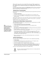
...the central monitoring station when you are not displayed if Streamlining is transmitting. Account numbers are testing the system. 2. For wireless sensors that don't respond, use an ITI RF Sniffer (60-401) test tool to the central station (or pager). ¾ To test communication with alpha-...SnapCard) should hear for 1½ minutes or more out in alarm or user number, and 7468 = last four digits of the panel. Verify that the system is correct. 3. Activate the appropriate device to verify configuration programming. ¾ To Test Outputs: 1. Verify that the correct alarm...
...the central monitoring station when you are not displayed if Streamlining is transmitting. Account numbers are testing the system. 2. For wireless sensors that don't respond, use an ITI RF Sniffer (60-401) test tool to the central station (or pager). ¾ To test communication with alpha-...SnapCard) should hear for 1½ minutes or more out in alarm or user number, and 7468 = last four digits of the panel. Verify that the system is correct. 3. Activate the appropriate device to verify configuration programming. ¾ To Test Outputs: 1. Verify that the correct alarm...

Installation Instructions
Page 76
...la c k G re e n R ed R J -3 1 X P h o n e J a c k (C A -3 8 A In C a n a d a ) G ry R ed W h ite O r Y e llo w R J -3 1 X P h o n e L in a l 1 6 F o r R e g u la r Z o n e C o m m o n C o n n e c tio n If Z o n e 6 IS S e t U p F o r 2 -W ir e S m o k e D e te c to r) 1 - T h e P e r m is s io n O f T h e L o c a l A u th o r ity H a v in g J u r is te d S y s te m s ) . S nap C a rd H eader P a n e l E e a rth G r o u n d C o n n e c tio n P ip e W a te r P ip e G r o u n d C la m p T e s t S y s te m W e e k ly O ff A 1 p re s s b o th N o D e la y B 4 p re s s b o th...
...la c k G re e n R ed R J -3 1 X P h o n e J a c k (C A -3 8 A In C a n a d a ) G ry R ed W h ite O r Y e llo w R J -3 1 X P h o n e L in a l 1 6 F o r R e g u la r Z o n e C o m m o n C o n n e c tio n If Z o n e 6 IS S e t U p F o r 2 -W ir e S m o k e D e te c to r) 1 - T h e P e r m is s io n O f T h e L o c a l A u th o r ity H a v in g J u r is te d S y s te m s ) . S nap C a rd H eader P a n e l E e a rth G r o u n d C o n n e c tio n P ip e W a te r P ip e G r o u n d C la m p T e s t S y s te m W e e k ly O ff A 1 p re s s b o th N o D e la y B 4 p re s s b o th...
