Installation Instructions
Page 6
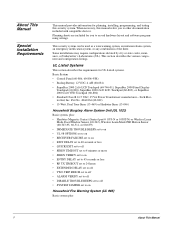
... included with compatible devices. Planning sheets are included for planning, installing, programming, and testing this manual refers you to on Household Fire Warning System (UL 985) Basic system plus : • Hardwire Magnetic Contact (Sentrol part # 1075-N or 1038T-N) or Wireless Learn Mode Door/Window Sensor (60-362), Wireless Learn Mode PIR Motion Sensor (60-703-95, 60-511, or 60-639) • IMMEDIATE TROUBLE BEEPS set to on • UL 98 OPTIONS set to on • RECEIVER FAILURE set to on • EXIT DELAY set to 60 seconds...
... included with compatible devices. Planning sheets are included for planning, installing, programming, and testing this manual refers you to on Household Fire Warning System (UL 985) Basic system plus : • Hardwire Magnetic Contact (Sentrol part # 1075-N or 1038T-N) or Wireless Learn Mode Door/Window Sensor (60-362), Wireless Learn Mode PIR Motion Sensor (60-703-95, 60-511, or 60-639) • IMMEDIATE TROUBLE BEEPS set to on • UL 98 OPTIONS set to on • RECEIVER FAILURE set to on • EXIT DELAY set to 60 seconds...
Installation Instructions
Page 7
... On Disabled On 30 Sec. SIA System Requirements SIA system requirements are programmed into sensor group 26 • IMMEDIATE TROUBLE BEEPS set to on • UL 98 OPTIONS set to on • RECEIVER FAILURE set to on • SIREN VERIFY set to on page 1, plus: • If multiple annunciation is required, use Hardwire Siren part no.13-046. Note UL requirements take priority over SIA requirements. • Hardwire Smoke Detector: System Sensor models...
... On Disabled On 30 Sec. SIA System Requirements SIA system requirements are programmed into sensor group 26 • IMMEDIATE TROUBLE BEEPS set to on • UL 98 OPTIONS set to on • RECEIVER FAILURE set to on • SIREN VERIFY set to on page 1, plus: • If multiple annunciation is required, use Hardwire Siren part no.13-046. Note UL requirements take priority over SIA requirements. • Hardwire Smoke Detector: System Sensor models...

Installation Instructions
Page 9
... Mode wireless sensors and touchpads. • Phone Line Connection: Allows the panel to install the system control panel. Installing the System Installing the System • Bus A and B: Input and output that provide communication between bus devices and the panel. • 2 Onboard Outputs: One 12-volt and one 2-wire smoke detector loop input, and two outputs that can be set up to activate other signalling devices, based on system events. • 6 Supervised Hardwire Zones: Factory programmed inputs for various hardwired detectors (see "Accessory Modules...
... Mode wireless sensors and touchpads. • Phone Line Connection: Allows the panel to install the system control panel. Installing the System Installing the System • Bus A and B: Input and output that provide communication between bus devices and the panel. • 2 Onboard Outputs: One 12-volt and one 2-wire smoke detector loop input, and two outputs that can be set up to activate other signalling devices, based on system events. • 6 Supervised Hardwire Zones: Factory programmed inputs for various hardwired detectors (see "Accessory Modules...
Installation Instructions
Page 15
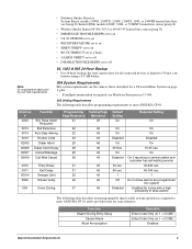
..., 2-wire smoke detectors by the following manufacturers: • System Sensor models 2100D, 2100TD, 2100S, 2100TS, 2400, 2400TH • Sentrol (ESL) models 429AT, 521B, 521BXT-models 521B and 521BXT require the following dip switch settings: 1-on before entering the LEARN SENSORS menu. Connecting a PIR Motion Detector Connecting 2-Wire Smoke Detectors Zone input 6 can handle up (in program mode) must be set up for complete details. See ONBOARD OPTIONS- The maximum loop resistance for 2-wire smoke detectors connected to the panel as a common loop connection...
..., 2-wire smoke detectors by the following manufacturers: • System Sensor models 2100D, 2100TD, 2100S, 2100TS, 2400, 2400TH • Sentrol (ESL) models 429AT, 521B, 521BXT-models 521B and 521BXT require the following dip switch settings: 1-on before entering the LEARN SENSORS menu. Connecting a PIR Motion Detector Connecting 2-Wire Smoke Detectors Zone input 6 can handle up (in program mode) must be set up for complete details. See ONBOARD OPTIONS- The maximum loop resistance for 2-wire smoke detectors connected to the panel as a common loop connection...
Installation Instructions
Page 25
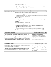
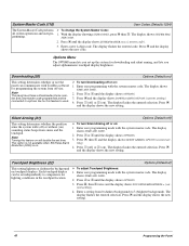
Each security access code (Installer, Dealer, System Master, or User) must have the panel account number 1. Press ƒ again to advance to global settings OR Press A or B to display PARTITION 1, then press ƒ to advance to perform any programming. Downloader Code (0000) Security-Global (Default = 12345) The 5-digit downloader code is used in conjunction with phone numbers can be unique. The down-loader operator must be changed. The display flashes the The Downloader Code cannot be used to initiate the...
Each security access code (Installer, Dealer, System Master, or User) must have the panel account number 1. Press ƒ again to advance to global settings OR Press A or B to display PARTITION 1, then press ƒ to advance to perform any programming. Downloader Code (0000) Security-Global (Default = 12345) The 5-digit downloader code is used in conjunction with phone numbers can be unique. The down-loader operator must be changed. The display flashes the The Downloader Code cannot be used to initiate the...
Installation Instructions
Page 26
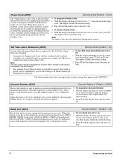
... the new setting. 21 Programming the Panel SIA False Alarm Reduction (0003) Security-Global (Default = on ). The display flashes the entered setting. 2. Press ƒ and the display shows the new setting. Account numbers must be configured for "Exterior Siren" (016xx) for the arming level beeps to be changed (unless you enter the program mode by using an access code. When this feature is not affected. ¾ To turn Quick Arm off ) Quick Arm allows system arming without entering an access code. The panel...
... the new setting. 21 Programming the Panel SIA False Alarm Reduction (0003) Security-Global (Default = on ). The display flashes the entered setting. 2. Press ƒ and the display shows the new setting. Account numbers must be configured for "Exterior Siren" (016xx) for the arming level beeps to be changed (unless you enter the program mode by using an access code. When this feature is not affected. ¾ To turn Quick Arm off ) Quick Arm allows system arming without entering an access code. The panel...
Installation Instructions
Page 28
...). The display flashes the entered sensor number. tral monitoring station. 2. During an audible alarm, keyswitch sensors can be armed only after siren timeout expires. The system can disarm the system (which sends a cancel report to a hardwire zone input or a wireless door or window sensor. 1. To enter *, press and hold 9 for UL 1635 listed installations. ¾ To program a Central Station Phone Number: 1. Press ƒ and the display shows the new number. With the display showing DURESS CODE nnnn (current code...
...). The display flashes the entered sensor number. tral monitoring station. 2. During an audible alarm, keyswitch sensors can be armed only after siren timeout expires. The system can disarm the system (which sends a cancel report to a hardwire zone input or a wireless door or window sensor. 1. To enter *, press and hold 9 for UL 1635 listed installations. ¾ To program a Central Station Phone Number: 1. Press ƒ and the display shows the new number. With the display showing DURESS CODE nnnn (current code...

Installation Instructions
Page 29
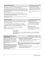
...; Force Armed • Hardwire Zone Trouble (open or short) • Supervisory (wireless devices) • Low Battery (wireless devices) • Other non-alarm related conditions ¾ To turn High-Level Reports off or on ). Open/Close Rpts (0103-cs phone 1, 0113-cs phone 2) When this setting is armed (closed) or disarmed (opened). Press ƒ and the display shows the new setting. The panel makes up by The display flashes the entered setting. Phones-CS Phone 1-2 (Default=off) ¾ To turn Backup...
...; Force Armed • Hardwire Zone Trouble (open or short) • Supervisory (wireless devices) • Low Battery (wireless devices) • Other non-alarm related conditions ¾ To turn High-Level Reports off or on ). Open/Close Rpts (0103-cs phone 1, 0113-cs phone 2) When this setting is armed (closed) or disarmed (opened). Press ƒ and the display shows the new setting. The panel makes up by The display flashes the entered setting. Phones-CS Phone 1-2 (Default=off) ¾ To turn Backup...
Installation Instructions
Page 30
... 3) Phones-Pager Phone 1-3 (Default=off) When this setting is used for one second. With the display showing PHONE NUMBER _ and # characters. (or current number), enter the desired pager To enter pauses, press C. The display flashes the entered number. Press ƒ and the display shows the new setting. The display flashes the entered setting. 2. The following conditions: • Force Armed • Hardwire Zone Trouble (open or short) • Supervisory (wireless devices) • Low Battery (wireless devices) ¾ To turn...
... 3) Phones-Pager Phone 1-3 (Default=off) When this setting is used for one second. With the display showing PHONE NUMBER _ and # characters. (or current number), enter the desired pager To enter pauses, press C. The display flashes the entered number. Press ƒ and the display shows the new setting. The display flashes the entered setting. 2. The following conditions: • Force Armed • Hardwire Zone Trouble (open or short) • Supervisory (wireless devices) • Low Battery (wireless devices) ¾ To turn...
Installation Instructions
Page 42
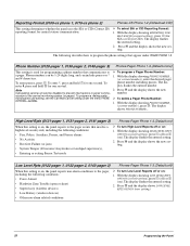
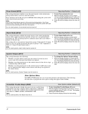
... change the System Tamper setting: 1. The display flashes the entered setting. 2. This setting affects sensors/zones learned into alarm if several incorrect access codes (40 consecutive keystrokes) are entered. • Whether or not the panel reports to the central station if a bus device stops communicating with the panel. • Whether or not the panel reports to the central station. Force Armed (0515) Reporting-Partition 1 (Default=off ). Note For UL Listed systems, System Tamper must be turned off...
... change the System Tamper setting: 1. The display flashes the entered setting. 2. This setting affects sensors/zones learned into alarm if several incorrect access codes (40 consecutive keystrokes) are entered. • Whether or not the panel reports to the central station if a bus device stops communicating with the panel. • Whether or not the panel reports to the central station. Force Armed (0515) Reporting-Partition 1 (Default=off ). Note For UL Listed systems, System Tamper must be turned off...
Installation Instructions
Page 44
... the BYPASS button until the LED flashes three times. ple, a word from the list counts as follows: Zone 2: 17-Instant Interior Follower Zone 3: 13-Instant Perimeter Zone 4: 13-Instant Perimeter Zone 5: 13-Instant Perimeter • Hardwire Zones-trip the zone into the selected sensor group. The display shows the complete text name. To change group assignment after entering the last 3-digit character/word numbers. Wireless Door/Window Sensors with six factory programmed onboard hardwire zones. To stop learning sensors into panel...
... the BYPASS button until the LED flashes three times. ple, a word from the list counts as follows: Zone 2: 17-Instant Interior Follower Zone 3: 13-Instant Perimeter Zone 4: 13-Instant Perimeter Zone 5: 13-Instant Perimeter • Hardwire Zones-trip the zone into the selected sensor group. The display shows the complete text name. To change group assignment after entering the last 3-digit character/word numbers. Wireless Door/Window Sensors with six factory programmed onboard hardwire zones. To stop learning sensors into panel...

Installation Instructions
Page 46
... B once. Modules-Bus Devices (Default=on) ¾ To turn the smoke verification feature off : 1. The last two digits represent how the output responds such as an alarm, open sensor, or arming the system. The display shows DEVICE ID (current ID). 2. The display shows OUTPUT n (current setting). 4. The display flashes the entered selection. Acc. Modules-SnapCards (Defaults: Output 1=01400, Output 2=00410, Output 3=00903, Output 4=01003) This setting lets you set panel zone input...
... B once. Modules-Bus Devices (Default=on) ¾ To turn the smoke verification feature off : 1. The last two digits represent how the output responds such as an alarm, open sensor, or arming the system. The display shows DEVICE ID (current ID). 2. The display shows OUTPUT n (current setting). 4. The display flashes the entered selection. Acc. Modules-SnapCards (Defaults: Output 1=01400, Output 2=00410, Output 3=00903, Output 4=01003) This setting lets you set panel zone input...
Installation Instructions
Page 50
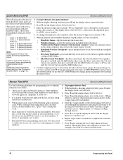
...the display shows the new setting. Press ƒ and the display shows the new setting. 45 Programming the Panel Press ƒ and the display shows the new code. Silent Arming (21) Options (Default=off ) or without (on : 1. System Master Code (110) User Codes (Default=1234) The System Master Code performs ¾ To change the System Master Code: all system operations and user pro- 1. Enter user programming mode with the system master code. Note Turning this feature to 3 (brightest background). With the display showing USER CODES, press ƒ then B. The display flashes...
...the display shows the new setting. Press ƒ and the display shows the new setting. 45 Programming the Panel Press ƒ and the display shows the new code. Silent Arming (21) Options (Default=off ) or without (on : 1. System Master Code (110) User Codes (Default=1234) The System Master Code performs ¾ To change the System Master Code: all system operations and user pro- 1. Enter user programming mode with the system master code. Note Turning this feature to 3 (brightest background). With the display showing USER CODES, press ƒ then B. The display flashes...
Installation Instructions
Page 52
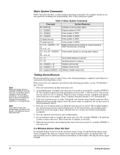
... a dealer sensor test Testing Zones/Sensors We recommend that sensor is not programmed) and OK. 4. When all sensors/zones and touchpad panics have been tested, the display shows SENSOR TEST OK or ZONES ALL TESTED (fixed display touchpads). 5. If all sensors/zones and touchpad panics have been tested, press 1 + installer CODE to the system users guide. Note If you need more time to AWAY 2 or 3 + CODE + 4 or 2 or 3 + 4 Makes entry/exit doors instant (4 must be pressed within five seconds of test time. 7. At an alphanumeric touchpad, enter the sensor test mode by...
... a dealer sensor test Testing Zones/Sensors We recommend that sensor is not programmed) and OK. 4. When all sensors/zones and touchpad panics have been tested, the display shows SENSOR TEST OK or ZONES ALL TESTED (fixed display touchpads). 5. If all sensors/zones and touchpad panics have been tested, press 1 + installer CODE to the system users guide. Note If you need more time to AWAY 2 or 3 + CODE + 4 or 2 or 3 + 4 Makes entry/exit doors instant (4 must be pressed within five seconds of test time. 7. At an alphanumeric touchpad, enter the sensor test mode by...
Installation Instructions
Page 53
... , enter 1 + system master CODE and refer to verify correct operation. 4. The display shows PHONE TEST and the touchpad sounds one sensor of each output as programmed. 4. When you are produced from these sirens. Activate the appropriate device to trigger each type (fire, intrusion, etc.) to the "Troubleshooting" section. Testing Central Station/Pager Communication After performing sensor and phone tests, check that the alarms were received. Table 5 describes pager system event codes. Contact the central monitoring station...
... , enter 1 + system master CODE and refer to verify correct operation. 4. The display shows PHONE TEST and the touchpad sounds one sensor of each output as programmed. 4. When you are produced from these sirens. Activate the appropriate device to trigger each type (fire, intrusion, etc.) to the "Troubleshooting" section. Testing Central Station/Pager Communication After performing sensor and phone tests, check that the alarms were received. Table 5 describes pager system event codes. Contact the central monitoring station...
Installation Instructions
Page 55
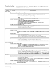
... bypass a 24-hour sensor that panel is not programmed or set to on (see the ACCESSORY MODULES-BUS DEVICES menu). Check your records to see the user programming OPTIONS menu). Call Technical Support for an indication of the problem. Alphanumeric Touchpads Display shows all monitored perimeter doors and windows are closed . 2. Arming and Disarming System protests and won 't disarm. 1. If arming to level 2, make sure all perimeter and interior sensors are closed . 3. Disarming using the Downloader. 3. The installer code...
... bypass a 24-hour sensor that panel is not programmed or set to on (see the ACCESSORY MODULES-BUS DEVICES menu). Check your records to see the user programming OPTIONS menu). Call Technical Support for an indication of the problem. Alphanumeric Touchpads Display shows all monitored perimeter doors and windows are closed . 2. Arming and Disarming System protests and won 't disarm. 1. If arming to level 2, make sure all perimeter and interior sensors are closed . 3. Disarming using the Downloader. 3. The installer code...
Installation Instructions
Page 56
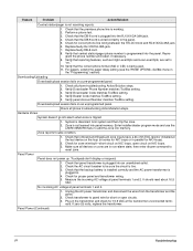
... setting. System is not receiving reports. 1. Enter installer/dealer program mode and use the LEARN SENSORS menu to panel wire for N/O loops). 2. Check for correct phone line wiring between the TELCO block and RJ-31X/CA-38A jack. 6. Touchpads don't display or respond. 1. Check transformer to add the zone into the panel. Panel Power (Continued) 51 Troubleshooting Check that reporting features, such as High Level Rpts and Low Level Rpts, are in non-alarm...
... setting. System is not receiving reports. 1. Enter installer/dealer program mode and use the LEARN SENSORS menu to panel wire for N/O loops). 2. Check for correct phone line wiring between the TELCO block and RJ-31X/CA-38A jack. 6. Touchpads don't display or respond. 1. Check transformer to add the zone into the panel. Panel Power (Continued) 51 Troubleshooting Check that reporting features, such as High Level Rpts and Low Level Rpts, are in non-alarm...
Installation Instructions
Page 57
... panel terminals 1 and 2. Replace cord if necessary. 5. Enter program mode and configure output (see ACCESSORY MODULES-BUS DEVICES-SNAP CARD, or ONBOARD OPTIONS-OUTPUT 1, 2 in the "Programming" section and the tables in battery test), the condition clears. It should read about 16.5 VAC. 3. With the AC power transformer plugged in place. Reverse the phone wires connected to an outlet with the provided screw. 4. Wireless Sensor and Touchpad Batteries Troubleshooting...
... panel terminals 1 and 2. Replace cord if necessary. 5. Enter program mode and configure output (see ACCESSORY MODULES-BUS DEVICES-SNAP CARD, or ONBOARD OPTIONS-OUTPUT 1, 2 in the "Programming" section and the tables in battery test), the condition clears. It should read about 16.5 VAC. 3. With the AC power transformer plugged in place. Reverse the phone wires connected to an outlet with the provided screw. 4. Wireless Sensor and Touchpad Batteries Troubleshooting...
Installation Instructions
Page 58
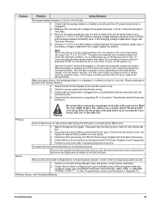
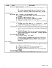
...Enter program mode and learn touchpad into antenna housing mounted on top of sensor (from a wireless touchpad. 1. Check the sensor battery for low voltage. Verify that touchpad battery is installed up into memory. Check that panel loop antenna is installed. 3. Remove sensor from mounted location and test from the device. Testing the sensor/touchpad with good battery information. Sensor tamper switch is tripped-sensor cover is off, not latched securely, or sensor is too far away. Replace batteries, if necessary. Feature Problem Action/Solution System...
...Enter program mode and learn touchpad into antenna housing mounted on top of sensor (from a wireless touchpad. 1. Check the sensor battery for low voltage. Verify that touchpad battery is installed up into memory. Check that panel loop antenna is installed. 3. Remove sensor from mounted location and test from the device. Testing the sensor/touchpad with good battery information. Sensor tamper switch is tripped-sensor cover is off, not latched securely, or sensor is too far away. Replace batteries, if necessary. Feature Problem Action/Solution System...
Installation Instructions
Page 73
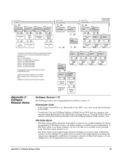
... Alarm is off , Silent Arming is not available in user programming. Downloader Code • If the Dealer Code (0002) is NOT annunciated on exterior siren output during an arming level change that is initiated by a memory clear operation using the Installer Code if the Dealer Code has been set , the Installer Code (0001) can't view or edit the Downloader Code (0000) • Downloader Code and CS Phone Numbers (0100/0110) are listed below: Zone 1: 10-Entry/Exit Zone 2: 17-Instant...
... Alarm is off , Silent Arming is not available in user programming. Downloader Code • If the Dealer Code (0002) is NOT annunciated on exterior siren output during an arming level change that is initiated by a memory clear operation using the Installer Code if the Dealer Code has been set , the Installer Code (0001) can't view or edit the Downloader Code (0000) • Downloader Code and CS Phone Numbers (0100/0110) are listed below: Zone 1: 10-Entry/Exit Zone 2: 17-Instant...


