Installation Instructions
Page 4
... This Manual 1 Special Installation Requirements 1 UL Listed Systems ...1 UL-Canada Listed Systems ...3 Planning the Installation 3 Standard Panel ...3 Touchpads ...3 SnapCard ...3 Installing the System 4 Determine the Panel Location ...4 Total System Power and Wire Length Guidelines 5 Mounting the Panel ...6 Identify Panel Components ...7 Connecting the Panel to Earth Ground ...7 Installing Optional SnapCards ...8 Installing Optional Hardwire Input Modules (HIMs 8 Connecting Detection Devices to Panel Zone Inputs...
... This Manual 1 Special Installation Requirements 1 UL Listed Systems ...1 UL-Canada Listed Systems ...3 Planning the Installation 3 Standard Panel ...3 Touchpads ...3 SnapCard ...3 Installing the System 4 Determine the Panel Location ...4 Total System Power and Wire Length Guidelines 5 Mounting the Panel ...6 Identify Panel Components ...7 Connecting the Panel to Earth Ground ...7 Installing Optional SnapCards ...8 Installing Optional Hardwire Input Modules (HIMs 8 Connecting Detection Devices to Panel Zone Inputs...
Installation Instructions
Page 6
...manual refers you to record hardware layout and software programming settings. Planning sheets are included for UL Listed systems. Basic System • Control Panel (60-806, 60-806-95R) • Backup Battery, 12 VDC, 4 AH (60-681) • SuperBus 2000 2x16 LCD Touchpad (60-746-01), SuperBus 2000 Fixed Display Touchpad (60...to off • SYSTEM TAMPER set to other documentation included with compatible devices. When necessary, this security system. This security system can be used as a wire warning system, an intrusion alarm system, an emergency notification system, or any combination...
...manual refers you to record hardware layout and software programming settings. Planning sheets are included for UL Listed systems. Basic System • Control Panel (60-806, 60-806-95R) • Backup Battery, 12 VDC, 4 AH (60-681) • SuperBus 2000 2x16 LCD Touchpad (60-746-01), SuperBus 2000 Fixed Display Touchpad (60...to off • SYSTEM TAMPER set to other documentation included with compatible devices. When necessary, this security system. This security system can be used as a wire warning system, an intrusion alarm system, an emergency notification system, or any combination...
Installation Instructions
Page 20
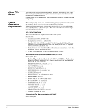
Connecting the Phone Line to the Panel with a DB-8 Cord After installing the RJ-31X jack, you are ready to connect the phone line to the "Troubleshooting" section of this manual if problems persist. Installing an RJ-31X Phone Jack 3. Connect the green, brown, gray, and red flying leads from ... still be accessed from the 4-conductor cable to the black and white (or yellow) wires of the phone system which prevents panel access from the DB-8 cord to panel terminals 18, 19, 20, and 21 (see D in Figure 16). 4. At the TELCO protector block, remove the premises phone lines (lines from...
Connecting the Phone Line to the Panel with a DB-8 Cord After installing the RJ-31X jack, you are ready to connect the phone line to the "Troubleshooting" section of this manual if problems persist. Installing an RJ-31X Phone Jack 3. Connect the green, brown, gray, and red flying leads from ... still be accessed from the 4-conductor cable to the black and white (or yellow) wires of the phone system which prevents panel access from the DB-8 cord to panel terminals 18, 19, 20, and 21 (see D in Figure 16). 4. At the TELCO protector block, remove the premises phone lines (lines from...
Installation Instructions
Page 21
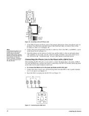
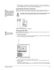
...controlled by a plug-in stepdown transformer that is powered up. Proceed to dial out and make phone calls. The panel must be powered up using the sequence of the panel circuit board (see Figure 19). Figure 18. Connect the battery leads to the battery terminals as shown in the power transformer at this manual... in the upper- Connecting the AC Power Transformer The panel must be powered by a switch or ground fault circuit interrupt (GFCI). Black Backup Battery Connections Red Installing the System Red Black Battery Figure 19. Alphanumeric touchpads display SCANNING ...
...controlled by a plug-in stepdown transformer that is powered up. Proceed to dial out and make phone calls. The panel must be powered up using the sequence of the panel circuit board (see Figure 19). Figure 18. Connect the battery leads to the battery terminals as shown in the power transformer at this manual... in the upper- Connecting the AC Power Transformer The panel must be powered by a switch or ground fault circuit interrupt (GFCI). Black Backup Battery Connections Red Installing the System Red Black Battery Figure 19. Alphanumeric touchpads display SCANNING ...
Installation Instructions
Page 25
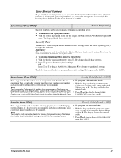
...With the display showing INSTALLER CODE ciated with downloader pro- ¾ To program a Downloader Code: gramming. Programming the Panel 20 Shortcut numbers in this heading shows the Downloader Code shortcut to be deleted or cleared from any setting location within tier...program the security settings that setting. To change code. To change the entered code. Downloader Code (0000) System Programming Shortcut numbers can be changed. Important ! Downloader Code to its default setting, enter 4321 in the procedure above. 2. For example this manual appear in ...
...With the display showing INSTALLER CODE ciated with downloader pro- ¾ To program a Downloader Code: gramming. Programming the Panel 20 Shortcut numbers in this heading shows the Downloader Code shortcut to be deleted or cleared from any setting location within tier...program the security settings that setting. To change code. To change the entered code. Downloader Code (0000) System Programming Shortcut numbers can be changed. Important ! Downloader Code to its default setting, enter 4321 in the procedure above. 2. For example this manual appear in ...


