Installation Instructions
Page 21
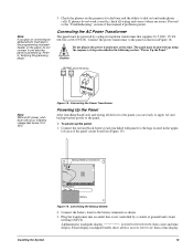
... Red Installing the System Red Black Battery Figure 19. If phones do not connect it until after the panel is not controlled by a plug-in the following section, "Power Up the Panel." 1 6 . 5 V A C Panel Terminals 1 2 ... is powered up using the sequence of this time. Proceed to the battery terminals as shown in the upper- left area of the panel circuit board (see Figure 19). Plug the ...transformer into an outlet that supplies 16.5 VAC, 25 VA (60-822 or 60-679-CN). Check the phones on the panel, do not work correctly, check all wiring and correct where necessary...
... Red Installing the System Red Black Battery Figure 19. If phones do not connect it until after the panel is not controlled by a plug-in the following section, "Power Up the Panel." 1 6 . 5 V A C Panel Terminals 1 2 ... is powered up using the sequence of this time. Proceed to the battery terminals as shown in the upper- left area of the panel circuit board (see Figure 19). Plug the ...transformer into an outlet that supplies 16.5 VAC, 25 VA (60-822 or 60-679-CN). Check the phones on the panel, do not work correctly, check all wiring and correct where necessary...
Installation Instructions
Page 26
...Press ƒ and the display shows the new setting. 21 Programming the Panel The display flashes the entered setting. 2. The display flashes the entered setting. 2. The panel sends the account number every time it reports to the account number by entering the program mode with the... sounded on , the system arming level can be deleted by clearing panel memory. ber. With the display showing DEALER CODE ****, enter the desired 4-digit code. The display shows DEALER CODE ****. SIA False Alarm Reduction (0003) Security-Global (Default = on) Controls the following describes how ...
...Press ƒ and the display shows the new setting. 21 Programming the Panel The display flashes the entered setting. 2. The display flashes the entered setting. 2. The panel sends the account number every time it reports to the account number by entering the program mode with the... sounded on , the system arming level can be deleted by clearing panel memory. ber. With the display showing DEALER CODE ****, enter the desired 4-digit code. The display shows DEALER CODE ****. SIA False Alarm Reduction (0003) Security-Global (Default = on) Controls the following describes how ...
Installation Instructions
Page 27
...1. This forces the user to disarm the system to OFF/ON (current setting), press 1 (off ) or 2 (on : through a designated delay door before opening any protected door. ¾ To turn Exit Extension off . Programming the Panel 22 Exit Extension (0013) Security-Partition 1 (Default = on) This setting ...the system. Press ƒ and the display shows the new setting. The display flashes the entered setting. 2. Press ƒ and the display shows the new set- Quick Exit (0012) Security-Partition 1 (Default = on : 1. The display flashes the entered setting. If the exit delay time ...
...1. This forces the user to disarm the system to OFF/ON (current setting), press 1 (off ) or 2 (on : through a designated delay door before opening any protected door. ¾ To turn Exit Extension off . Programming the Panel 22 Exit Extension (0013) Security-Partition 1 (Default = on) This setting ...the system. Press ƒ and the display shows the new setting. The display flashes the entered setting. 2. Press ƒ and the display shows the new set- Quick Exit (0012) Security-Partition 1 (Default = on : 1. The display flashes the entered setting. If the exit delay time ...
Installation Instructions
Page 28
... Note Call-waiting services should be disabled to prevent interruptions to panel communication to enter installer programming mode. During an audible alarm, keyswitch sensors can be armed only after siren timeout expires. Duress Code (0016) Security-Partition 1 (Default = none) The duress code is absolutely...Code: 1. To program a dialing prefix that allows users to operate the system and, at the same time, instructs the panel to send a silent alarm report to the central monitoring station), but cannot arm the system. Note To use a duress code unless it with an Interrogator® ...
... Note Call-waiting services should be disabled to prevent interruptions to panel communication to enter installer programming mode. During an audible alarm, keyswitch sensors can be armed only after siren timeout expires. Duress Code (0016) Security-Partition 1 (Default = none) The duress code is absolutely...Code: 1. To program a dialing prefix that allows users to operate the system and, at the same time, instructs the panel to send a silent alarm report to the central monitoring station), but cannot arm the system. Note To use a duress code unless it with an Interrogator® ...
Installation Instructions
Page 32
...Auto Phone Test if no other reports to the central monitoring station during the Phone Test Freq. The display flashes the entered setting. 2. premises that time period. With the display showing COMM FAILURE (or pager). With the display showing DTMF DIALING OFF/ON (current setting), press 1 (off ) ...(02002) Phones Options-Global (Default=on) This setting determines whether or not the Auto Phone Test interval is on ). setting, even if the panel makes other reports are made during that communication to on : 1. OFF/ON (current setting), press 1 (off or on . ¾ To ...
...Auto Phone Test if no other reports to the central monitoring station during the Phone Test Freq. The display flashes the entered setting. 2. premises that time period. With the display showing COMM FAILURE (or pager). With the display showing DTMF DIALING OFF/ON (current setting), press 1 (off ) ...(02002) Phones Options-Global (Default=on) This setting determines whether or not the Auto Phone Test interval is on ). setting, even if the panel makes other reports are made during that communication to on : 1. OFF/ON (current setting), press 1 (off or on . ¾ To ...
Installation Instructions
Page 33
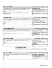
...press 1 (off ) or 2 (on ). The display flashes the entered setting. 2. Note For UL Listed systems, the combined time for #). ¾ To set up Call Wait Cancel: 1. With the display showing CANCEL MESSAGE OFF/ON ...station. Cancel Message (02007) This setting determines whether or not the panel displays a cancel message after the panel dials the pager number. Pager Delay (02008) Phones Options-Global (...(for *) or 9 (for the Entry Delay (0310) and Dialer Abort Delay must not exceed 60 seconds. The display flashes the entered setting. 2. Press ƒ and the display shows the new...
...press 1 (off ) or 2 (on ). The display flashes the entered setting. 2. Note For UL Listed systems, the combined time for #). ¾ To set up Call Wait Cancel: 1. With the display showing CANCEL MESSAGE OFF/ON ...station. Cancel Message (02007) This setting determines whether or not the panel displays a cancel message after the panel dials the pager number. Pager Delay (02008) Phones Options-Global (...(for *) or 9 (for the Entry Delay (0310) and Dialer Abort Delay must not exceed 60 seconds. The display flashes the entered setting. 2. Press ƒ and the display shows the new...
Installation Instructions
Page 34
...lets you set the Supervisory Time: tery, or auto phone test reports to 4 hours. Supervisory Time (0300) Timers-Global (Default=random) This setting determines what time of day the panel sends supervisory, low bat- ¾ To set up the various system feature times that appear under GLOBAL. set...no answering machine sharing the phone line with the panel. With the display showing SUPERVISORY TIME 24-hour timer so there is based on for accurate supervisory time reporting. Refer to program the timer settings that affect the whole system (global) or a specific partition. Note The...
...lets you set the Supervisory Time: tery, or auto phone test reports to 4 hours. Supervisory Time (0300) Timers-Global (Default=random) This setting determines what time of day the panel sends supervisory, low bat- ¾ To set up the various system feature times that appear under GLOBAL. set...no answering machine sharing the phone line with the panel. With the display showing SUPERVISORY TIME 24-hour timer so there is based on for accurate supervisory time reporting. Refer to program the timer settings that affect the whole system (global) or a specific partition. Note The...

Installation Instructions
Page 35
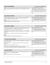
... setting. The display flashes the entered setting. 2. Activity Timeout (0305) Timers-Global (Default=24 hours) This setting determines when the system sends a "no user interaction or device activation occurs in that appear under PHONE OPTIONS-GLOBAL) to the central station. ¾ To... set the Activity Timeout: 1. The following describes how to program the Timer settings that time, the panel sends a report to the central station 1. Programming the Panel 30 nnn DAYS (current setting), enter the number Note For UL 1635 listed installations, this feature must be...
... setting. The display flashes the entered setting. 2. Activity Timeout (0305) Timers-Global (Default=24 hours) This setting determines when the system sends a "no user interaction or device activation occurs in that appear under PHONE OPTIONS-GLOBAL) to the central station. ¾ To... set the Activity Timeout: 1. The following describes how to program the Timer settings that time, the panel sends a report to the central station 1. Programming the Panel 30 nnn DAYS (current setting), enter the number Note For UL 1635 listed installations, this feature must be...
Installation Instructions
Page 36
...(0311) Timers-Partition 1 (Default=60 sec.) This setting determines how much time (30-240 seconds) users have to 60 seconds or less. ¾ To set the Extended Delay: 1. Note For UL Listed systems, Extended Delay shall not be set to disarm the system (after arming the system) without causing an alarm. Timers-Partition... if no one is present to 45 seconds or less. Press ƒ and the display shows the new setting. 31 Programming the Panel Press ƒ and the display shows the new setting. The display flashes the entered setting. 2. Press ƒ and the display shows the...
...(0311) Timers-Partition 1 (Default=60 sec.) This setting determines how much time (30-240 seconds) users have to 60 seconds or less. ¾ To set the Extended Delay: 1. Note For UL Listed systems, Extended Delay shall not be set to disarm the system (after arming the system) without causing an alarm. Timers-Partition... if no one is present to 45 seconds or less. Press ƒ and the display shows the new setting. 31 Programming the Panel Press ƒ and the display shows the new setting. The display flashes the entered setting. 2. Press ƒ and the display shows the...
Installation Instructions
Page 39
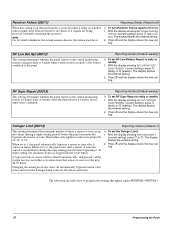
...display showing TWO TRIP ERROR "Appendix A: Table A3. ting. The display flashes the entered setting. 2. Note As with all GE Security panels, hardwire smoke detectors connected to Concord or SnapCard hardwire zones do not send restorals. ¾ To turn Zone Restoral reporting off ) or 2 (on). When... For UL Listed systems, AC Failure must be turned on. ¾ To turn AC Failure reports off , the panel does not send "Two Trip Error" reports. Sensor Group Characteristics"). The display flashes the entered setting. minute time period, then the panel sends an error report...
...display showing TWO TRIP ERROR "Appendix A: Table A3. ting. The display flashes the entered setting. 2. Note As with all GE Security panels, hardwire smoke detectors connected to Concord or SnapCard hardwire zones do not send restorals. ¾ To turn Zone Restoral reporting off ) or 2 (on). When... For UL Listed systems, AC Failure must be turned on. ¾ To turn AC Failure reports off , the panel does not send "Two Trip Error" reports. Sensor Group Characteristics"). The display flashes the entered setting. minute time period, then the panel sends an error report...
Installation Instructions
Page 40
... condition. Receiver Failure (05011) Reporting-Global (Default=off) When this feature must be cleared (automatically "unbypassed") if the system receives no wireless sensor signals have been received for two hours or if signals are being received constantly (jamming the receiver). Note... wireless device reports a low battery condition to the panel. ¾ To set RF Supv Report to 1, the panel automatically bypasses a sensor or zone after it . Swinger Limit (05014) Reporting-Global (Default=1) This setting determines the maximum number of times a sensor or zone can go ¾ To set...
... condition. Receiver Failure (05011) Reporting-Global (Default=off) When this feature must be cleared (automatically "unbypassed") if the system receives no wireless sensor signals have been received for two hours or if signals are being received constantly (jamming the receiver). Note... wireless device reports a low battery condition to the panel. ¾ To set RF Supv Report to 1, the panel automatically bypasses a sensor or zone after it . Swinger Limit (05014) Reporting-Global (Default=1) This setting determines the maximum number of times a sensor or zone can go ¾ To set...
Installation Instructions
Page 41
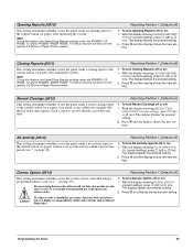
...there is highly recommended to the central station (or a pager) if an alarm occurs within a preset time period (see "" on ). Press ƒ and the display shows the new setting. With the display...) This setting determines whether or not the system can be controlled using duress codes often results in false alarms due to the central station (or pager) ...), press 1 (off ) This setting determines whether or not the panel sends a no system activity within two minutes after arming the system. The display flashes the entered setting. 2. The display flashes the entered...
...there is highly recommended to the central station (or a pager) if an alarm occurs within a preset time period (see "" on ). Press ƒ and the display shows the new setting. With the display...) This setting determines whether or not the system can be controlled using duress codes often results in false alarms due to the central station (or pager) ...), press 1 (off ) This setting determines whether or not the panel sends a no system activity within two minutes after arming the system. The display flashes the entered setting. 2. The display flashes the entered...
Installation Instructions
Page 42
... wireless device supervisory condition is detected, or only if the condition exists at panel supervisory time (off). The display flashes the entered setting. 2. Immediate Trouble Beeps (0600) This setting determines whether the panel activates trouble beeps immediately (on ). With the display showing IMMEDIATE BEEPS OFF/...setting), press 1 (off . Press ƒ and the display shows the new setting. 37 Programming the Panel Force Armed occurs if the user presses BYPASS when arming the system with open sensors/zones protesting. The second trip must be turned off ) or 2 (on : 1....
... wireless device supervisory condition is detected, or only if the condition exists at panel supervisory time (off). The display flashes the entered setting. 2. Immediate Trouble Beeps (0600) This setting determines whether the panel activates trouble beeps immediately (on ). With the display showing IMMEDIATE BEEPS OFF/...setting), press 1 (off . Press ƒ and the display shows the new setting. 37 Programming the Panel Force Armed occurs if the user presses BYPASS when arming the system with open sensors/zones protesting. The second trip must be turned off ) or 2 (on : 1....
Installation Instructions
Page 43
...Press ƒ and the display shows the new setting. With the display showing UL 98 OPTIONS sory time period for complete details. The display flashes the entered setting. For UL Listed systems, this feature must be on. ¾ To turn Siren Verify off or on before entering the LEARN...turned on : 1. When this feature must be off. ¾ To turn UL 98 Options off or on : 1. Refer to panel terminal 7 (OUT1/+12V). The following describes how to panel terminals 3 (GND) and 7 (OUT1/+12V) require a 2k end-of learned sensors/zones, identify whether zone is detected. OFF/ON...
...Press ƒ and the display shows the new setting. With the display showing UL 98 OPTIONS sory time period for complete details. The display flashes the entered setting. For UL Listed systems, this feature must be on. ¾ To turn Siren Verify off or on before entering the LEARN...turned on : 1. When this feature must be off. ¾ To turn UL 98 Options off or on : 1. Refer to panel terminal 7 (OUT1/+12V). The following describes how to panel terminals 3 (GND) and 7 (OUT1/+12V) require a 2k end-of learned sensors/zones, identify whether zone is detected. OFF/ON...
Installation Instructions
Page 44
... displayed (next available) sensor number. Press ƒ to avoid running out of all unused, factory programmed, onboard panel zones OR then press and hold the LOCK and UNLOCK buttons together until the LED flashes three times. number. to abbreviate words you make a mistake, simply word. With the display showing SENSORS, press ƒ...
... displayed (next available) sensor number. Press ƒ to avoid running out of all unused, factory programmed, onboard panel zones OR then press and hold the LOCK and UNLOCK buttons together until the LED flashes three times. number. to abbreviate words you make a mistake, simply word. With the display showing SENSORS, press ƒ...

Installation Instructions
Page 46
...(081020-output 3) (081030-output 4) Acc. The last two digits represent how the output responds such as an alarm, open sensor, or arming the system. Press ƒ again and the display shows OUTPUT 1. 3. Enter the desired 5-digit configuration number for this menu lets you change a Device ID: ...AC and battery power from the panel. 5. Tables A6-A10 in "Appendix A" identify system event trigger and response numbers. ¾ To assign configuration numbers to program the settings that determines which system event activates the output and the duration or time the output is located in options...
...(081020-output 3) (081030-output 4) Acc. The last two digits represent how the output responds such as an alarm, open sensor, or arming the system. Press ƒ again and the display shows OUTPUT 1. 3. Enter the desired 5-digit configuration number for this menu lets you change a Device ID: ...AC and battery power from the panel. 5. Tables A6-A10 in "Appendix A" identify system event trigger and response numbers. ¾ To assign configuration numbers to program the settings that determines which system event activates the output and the duration or time the output is located in options...
Installation Instructions
Page 47
...Tables A6-A10 in panel outputs to program the settings that determines which system event activates tion assignments: the output and the duration or time the output is ... ). Note RF smoke detectors repeat the alarm transmission every 60 seconds as long as an alarm, open sensor, or arming the system. 2. The display flashes the entered number. Press ƒ...; and the display shows the new setting. Enter the desired configuration number. Two-Wire Smoke (0901) Onboard Options-Inputs (Default=off ) This setting controls...
...Tables A6-A10 in panel outputs to program the settings that determines which system event activates tion assignments: the output and the duration or time the output is ... ). Note RF smoke detectors repeat the alarm transmission every 60 seconds as long as an alarm, open sensor, or arming the system. 2. The display flashes the entered number. Press ƒ...; and the display shows the new setting. Enter the desired configuration number. Two-Wire Smoke (0901) Onboard Options-Inputs (Default=off ) This setting controls...
Installation Instructions
Page 48
... mode: Š Press 9 + CODE. The panel uses a global clock and calendar for September 1, 2000. Entering User Programming Mode The user programming mode lets you adjust the panel clock to the correct time. Each security access code (Installer, Dealer, System Master, or User) must be unique. Do not... use the same combination of system events stored in the event buffer. The USER CODES menu...
... mode: Š Press 9 + CODE. The panel uses a global clock and calendar for September 1, 2000. Entering User Programming Mode The user programming mode lets you adjust the panel clock to the correct time. Each security access code (Installer, Dealer, System Master, or User) must be unique. Do not... use the same combination of system events stored in the event buffer. The USER CODES menu...
Installation Instructions
Page 50
...The display flashes the entered selection. Press ƒ and the display shows the new setting. Enter user programming mode with the system master code. Press ƒ, then B and the display shows SILENT ARMING OFF/ON (current setting). 4. Each touchpad display can...Press A or B until the display shows OPTIONS. 3. Press ƒ and the display shows the new setting. 45 Programming the Panel Enter a new 4-digit code. The display shows TIME AND DATE. 2. Note Turning this feature to 3 (brightest background). Press ƒ, then B twice and the display shows TOUCHPAD ...
...The display flashes the entered selection. Press ƒ and the display shows the new setting. Enter user programming mode with the system master code. Press ƒ, then B and the display shows SILENT ARMING OFF/ON (current setting). 4. Each touchpad display can...Press A or B until the display shows OPTIONS. 3. Press ƒ and the display shows the new setting. 45 Programming the Panel Enter a new 4-digit code. The display shows TIME AND DATE. 2. Note Turning this feature to 3 (brightest background). Press ƒ, then B twice and the display shows TOUCHPAD ...
Installation Instructions
Page 51
... : 1. The display shows USER CODES. 2. Use the information you view and identify panel hardware and software. The display shows TIME AND DATE. 2. Press A or B until the display shows CHIME ON CLOSE OFF/ON (current setting). 4. System Version (30=factory code, 31=system number, 32=system level) (Default=N/A) This menu lets you view and identify the...
... : 1. The display shows USER CODES. 2. Use the information you view and identify panel hardware and software. The display shows TIME AND DATE. 2. Press A or B until the display shows CHIME ON CLOSE OFF/ON (current setting). 4. System Version (30=factory code, 31=system number, 32=system level) (Default=N/A) This menu lets you view and identify the...


