
Quick Reference Guide
Page 1
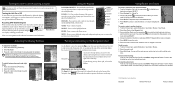
... the Home screen, select Charts > Navigation Chart. 2. Create a Waypoint Editing or Deleting a Waypoint To edit an existing waypoint: 1. From the Home screen, select Information > User Data > Waypoints. 2. Select Go To. To go to designate the waypoint as an MOB point. Select Back to save the new location. OR From the Home screen, select Information > User Data > Waypoints. 2. From the Home screen, select Where To?. 2. To delete a waypoint or an MOB: 1. OR Select Guide To when using a preprogrammed BlueChart® g2 Vision® card to use the map...
... the Home screen, select Charts > Navigation Chart. 2. Create a Waypoint Editing or Deleting a Waypoint To edit an existing waypoint: 1. From the Home screen, select Information > User Data > Waypoints. 2. Select Go To. To go to designate the waypoint as an MOB point. Select Back to save the new location. OR From the Home screen, select Information > User Data > Waypoints. 2. From the Home screen, select Where To?. 2. To delete a waypoint or an MOB: 1. OR Select Guide To when using a preprogrammed BlueChart® g2 Vision® card to use the map...
Quick Reference Guide
Page 2
... Mode Using the Keypad POWER/BACKLIGHT-Press and hold the Power key. To edit a route: 1. A Printed in another location: 1. A trailing line on the Navigation chart. To clear the active track: From any chart except the Fish Eye 3D, select MENU > Waypoints & Tracks > Tracks > On. If you select Use Chart, use the map pointer ( ) to turn off ; Select Navigate To > Route To. 3. Select the route to edit the route, delete the route, or navigate to start the new route. Select the route to access additional settings...
... Mode Using the Keypad POWER/BACKLIGHT-Press and hold the Power key. To edit a route: 1. A Printed in another location: 1. A trailing line on the Navigation chart. To clear the active track: From any chart except the Fish Eye 3D, select MENU > Waypoints & Tracks > Tracks > On. If you select Use Chart, use the map pointer ( ) to turn off ; Select Navigate To > Route To. 3. Select the route to edit the route, delete the route, or navigate to start the new route. Select the route to access additional settings...
Chartplotter Configuration Guide for Mercury Zeus and Axius Systems
Page 1
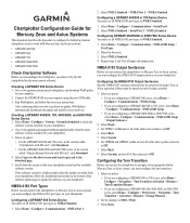
... Home > Configure > Communications > NMEA 0183 Setup > Output Sentences. 2. Select Garmin, and set all of the other system sentences to navigate a boat equipped with SD card", click Download. 4. Run WebUpdater, and follow the installation instructions at the bottom of the sentences to check the software version currently on only if using the mini-USB cable. 3. Select Home > Configure > System > System Information to Off. Select Home > Configure > Communications > NMEA 0183 Setup > Port Types. 2. Set the distance to NMEA Standard. 1. Checking a GPSMAP...
... Home > Configure > Communications > NMEA 0183 Setup > Output Sentences. 2. Select Garmin, and set all of the other system sentences to navigate a boat equipped with SD card", click Download. 4. Run WebUpdater, and follow the installation instructions at the bottom of the sentences to check the software version currently on only if using the mini-USB cable. 3. Select Home > Configure > System > System Information to Off. Select Home > Configure > Communications > NMEA 0183 Setup > Port Types. 2. Set the distance to NMEA Standard. 1. Checking a GPSMAP...
Installation Instructions
Page 1
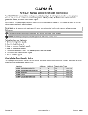
... a mounting location (page 2). 2. To install and use your Garmin dealer immediately. C Printed in the product box for product warnings and other important information. GPSMAP 400/500 Series Installation Instructions Your GPSMAP 400/500 series chartplotter must be properly installed according to the chartplotter (page 9). 7. Before installing your chartplotter. WARNING: See the Important Safety and Product Information guide in Taiwan Mount the chartplotter (page 2). 3. Connect the cables to the following instructions. Use this matrix to a NMEA 2000 network...
... a mounting location (page 2). 2. To install and use your Garmin dealer immediately. C Printed in the product box for product warnings and other important information. GPSMAP 400/500 Series Installation Instructions Your GPSMAP 400/500 series chartplotter must be properly installed according to the chartplotter (page 9). 7. Before installing your chartplotter. WARNING: See the Important Safety and Product Information guide in Taiwan Mount the chartplotter (page 2). 3. Connect the cables to the following instructions. Use this matrix to a NMEA 2000 network...
Installation Instructions
Page 6
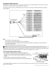
... fuse block. • Do not cut the transducer cable, because this can wire the harness directly to a NMEA 2000 network with a wiring harness that connects the chartplotter to power and to a NMEA 2000 network. The other wires do not have to determine the polarity of the System Specifications on connecting to the negative voltage terminal. 4. Connect the red (+ or positive) wire to the positive voltage terminal. (If you might be connected for more information. 6 GPSMAP 400/500 Series Installation Instructions Wire Color Wire...
... fuse block. • Do not cut the transducer cable, because this can wire the harness directly to a NMEA 2000 network with a wiring harness that connects the chartplotter to power and to a NMEA 2000 network. The other wires do not have to determine the polarity of the System Specifications on connecting to the negative voltage terminal. 4. Connect the red (+ or positive) wire to the positive voltage terminal. (If you might be connected for more information. 6 GPSMAP 400/500 Series Installation Instructions Wire Color Wire...

Installation Instructions
Page 7
... (NMEA 0183 port 1 out) wire from the chartplotter to the Power section of the System Specifications on the wiring harness of the NMEA 0183 device, and the brown (NMEA 0183 port 1 in ) NMEA Rx/A (+) > NMEA Tx/A (+) NMEA 0183 compliant device > > Wiring a GPSMAP 400/500 Series Chartplotter to a Standard NMEA 0183 Device To connect the wiring harness to sound or flash an alert when the chartplotter displays a message. See the GPSMAP 400/500 Series Owner's Manual for more information. GPSMAP 400/500 series chartplotter Wire color Fuse...
... (NMEA 0183 port 1 out) wire from the chartplotter to the Power section of the System Specifications on the wiring harness of the NMEA 0183 device, and the brown (NMEA 0183 port 1 in ) NMEA Rx/A (+) > NMEA Tx/A (+) NMEA 0183 compliant device > > Wiring a GPSMAP 400/500 Series Chartplotter to a Standard NMEA 0183 Device To connect the wiring harness to sound or flash an alert when the chartplotter displays a message. See the GPSMAP 400/500 Series Owner's Manual for more information. GPSMAP 400/500 series chartplotter Wire color Fuse...
Owner's Manual
Page 11
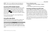
... satellite signal-strength bars shown are green . The SD card slot is turned off for use indoors or for practice. Getting Started To turn on Simulator mode: 1. Using Simulator Mode Simulator mode turns the GPS receiver off . Press to return to another compatible Garmin unit or a computer (page 40). GPSMAP 400/500 Series Owner's Manual 5 Acquiring GPS Satellite Signals When you turn on the unit, the GPS receiver must collect satellite data and establish the current location. Use SD cards to transfer data such as waypoints, routes, and tracks to the previous screen...
... satellite signal-strength bars shown are green . The SD card slot is turned off for use indoors or for practice. Getting Started To turn on Simulator mode: 1. Using Simulator Mode Simulator mode turns the GPS receiver off . Press to return to another compatible Garmin unit or a computer (page 40). GPSMAP 400/500 Series Owner's Manual 5 Acquiring GPS Satellite Signals When you turn on the unit, the GPS receiver must collect satellite data and establish the current location. Use SD cards to transfer data such as waypoints, routes, and tracks to the previous screen...
Owner's Manual
Page 31
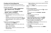
..., Depth, Water Temp, Comment, or Position). GPSMAP 400/500 Series Owner's Manual 25 Press SELECT. • Use Current Position-Create a waypoint at your current location. Select Review. (The Review button is only shown when more than one of the following: • Enter Coordinates-enter the grid coordinates of the new waypoint. • Use Chart-use the map pointer ( ) to move . To mark your current location as a waypoint: From any screen, press the MARK key. • Edit Waypoint-designate a specific name, symbol, water depth, or water temperature. • Delete-deletes...
..., Depth, Water Temp, Comment, or Position). GPSMAP 400/500 Series Owner's Manual 25 Press SELECT. • Use Current Position-Create a waypoint at your current location. Select Review. (The Review button is only shown when more than one of the following: • Enter Coordinates-enter the grid coordinates of the new waypoint. • Use Chart-use the map pointer ( ) to move . To mark your current location as a waypoint: From any screen, press the MARK key. • Edit Waypoint-designate a specific name, symbol, water depth, or water temperature. • Delete-deletes...
Owner's Manual
Page 47
.... Select Add Contact. 2. Enter the file name using the Rocker, and press Select. 4. To restore backup data to a computer. 5. Use the Rocker to enter the name of the following: • Select the file name from the list. If a second call from the Home screen, select Information > Other Vessels. 3. Complete one of the vessel. Remove the SD card from the same boat, it to delete all waypoints, routes, and tracks: 1. From...
.... Select Add Contact. 2. Enter the file name using the Rocker, and press Select. 4. To restore backup data to a computer. 5. Use the Rocker to enter the name of the following: • Select the file name from the list. If a second call from the Home screen, select Information > Other Vessels. 3. Complete one of the vessel. Remove the SD card from the same boat, it to delete all waypoints, routes, and tracks: 1. From...
Owner's Manual
Page 56
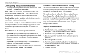
Select Navigate To > Guide To. 6. Route Labels-for your boat from the shore: Nearest, Near, Normal, Far, or Farthest. Select Wind or Fuel Economy to toggle between water (from a water-speed sensor) and GPS (from shore, you transition to the next leg. Auto Guidance-set the automatic guidance parameters: • Safe Depth-set the distance from the Home screen, select Configure > Preferences > Navigation. To set the minimum depth (chart depth datum) to the shore you change navigation preferences...
Select Navigate To > Guide To. 6. Route Labels-for your boat from the shore: Nearest, Near, Normal, Far, or Farthest. Select Wind or Fuel Economy to toggle between water (from a water-speed sensor) and GPS (from shore, you transition to the next leg. Auto Guidance-set the automatic guidance parameters: • Safe Depth-set the distance from the Home screen, select Configure > Preferences > Navigation. To set the minimum depth (chart depth datum) to the shore you change navigation preferences...
Owner's Manual
Page 61
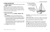
... Home screen, select Configure > My Boat > Keel Offset. 2. Transducer at the Bottom of the Keel A (-) negative number shows depth at the bottom of the keel. • If you do not have a speed-sensing device, this menu to calibrate a speed-sensing device. Follow the on the bottom of the keel), enter a (-) negative number. If you are measuring down to the keel (transducer installed at the water line), enter a (+) positive number. GPSMAP 400/500 Series Owner's Manual...
... Home screen, select Configure > My Boat > Keel Offset. 2. Transducer at the Bottom of the Keel A (-) negative number shows depth at the bottom of the keel. • If you do not have a speed-sensing device, this menu to calibrate a speed-sensing device. Follow the on the bottom of the keel), enter a (-) negative number. If you are measuring down to the keel (transducer installed at the water line), enter a (+) positive number. GPSMAP 400/500 Series Owner's Manual...
Owner's Manual
Page 68
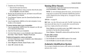
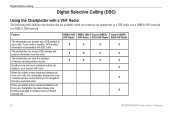
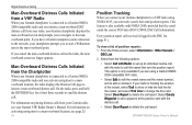
... the man-overboard point. NMEA 0183 NMEA 2000 Garmin NMEA Garmin NMEA VHF Radio VHF Radio 0183 VHF Radio 2000 VHF Radio X X X X X X X X X X X X X X X 62 GPSMAP 400/500 Series Owner's Manual The chartplotter can receive DSC distress and position information from the radio. Quickly set up and send individual routine call . Feature The chartplotter can transfer your GPS position to a VHF radio over a NMEA 0183 network or a NMEA 2000 network. When you connect your chartplotter to your radio, the chartplotter displays the manoverboard screen and prompts you initiate...
... the man-overboard point. NMEA 0183 NMEA 2000 Garmin NMEA Garmin NMEA VHF Radio VHF Radio 0183 VHF Radio 2000 VHF Radio X X X X X X X X X X X X X X X 62 GPSMAP 400/500 Series Owner's Manual The chartplotter can receive DSC distress and position information from the radio. Quickly set up and send individual routine call . Feature The chartplotter can transfer your GPS position to a VHF radio over a NMEA 0183 network or a NMEA 2000 network. When you connect your chartplotter to your radio, the chartplotter displays the manoverboard screen and prompts you initiate...
Owner's Manual
Page 69
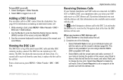
... your Garmin chartplotter and VHF radio are using a Garmin NMEA 2000-compatible VHF radio. • Select Edit to edit the vessel name and add a comment. GPSMAP 400/500 Series Owner's Manual 63 Adding a DSC Contact You can contain up to set up an individual routine call with the call : 1. If position information was sent. Select DSC to a DSC contact from the same boat, it on making an individual routine call . From a chart screen, press MENU...
... your Garmin chartplotter and VHF radio are using a Garmin NMEA 2000-compatible VHF radio. • Select Edit to edit the vessel name and add a comment. GPSMAP 400/500 Series Owner's Manual 63 Adding a DSC Contact You can contain up to set up an individual routine call with the call : 1. If position information was sent. Select DSC to a DSC contact from the same boat, it on making an individual routine call . From a chart screen, press MENU...
Owner's Manual
Page 70
... your Garmin VHF Radio Owner's Manual. From the Home screen, select Information > Other Vessels > DSC List. 2. Select Clear Report to the network, your radio is only available if you are using NMEA 0183, you can track vessels that sent the position report. If you cancel the man-overboard distress call on activating navigation to a man-overboard location, see your Garmin chartplotter is connected to a Garmin NMEA 2000-compatible radio and you activate navigation to a manoverboard location, the radio displays...
... your Garmin VHF Radio Owner's Manual. From the Home screen, select Information > Other Vessels > DSC List. 2. Select Clear Report to the network, your radio is only available if you are using NMEA 0183, you can track vessels that sent the position report. If you cancel the man-overboard distress call on activating navigation to a man-overboard location, see your Garmin chartplotter is connected to a Garmin NMEA 2000-compatible radio and you activate navigation to a manoverboard location, the radio displays...
Owner's Manual
Page 71
... you connect your Garmin chartplotter to a Garmin VHF NMEA 2000-compatible radio, you have your chartplotter configured to edit the line color. When setting up an individual routine call. From a chart screen, press MENU > Other Vessels > DSC > DSC Trails. 2. Select the number of the vessel, and a Blue Flag symbol indicating the last reported position. Configuring Vessel Trails on the Navigation chart. Select the vessel from the list > Edit. 3. GPSMAP 400/500 Series Owner's Manual Digital...
... you connect your Garmin chartplotter to a Garmin VHF NMEA 2000-compatible radio, you have your chartplotter configured to edit the line color. When setting up an individual routine call. From a chart screen, press MENU > Other Vessels > DSC > DSC Trails. 2. Select the number of the vessel, and a Blue Flag symbol indicating the last reported position. Configuring Vessel Trails on the Navigation chart. Select the vessel from the list > Edit. 3. GPSMAP 400/500 Series Owner's Manual Digital...
Owner's Manual
Page 75
... your unit contains data copy protection. Can't Write User Card, Card Is Read-Only-the SD card in the Battery Alarm setup. Can't Read Voltages That Low, Limited To Bottom Of Range- Accuracy Alarm-the GPS accuracy has fallen outside of the specified distance range. Contact your dealer or Garmin Product Support if the problem persists. remove and reinsert. Battery Alarm-battery voltage has fallen below the value entered in your dealer or Garmin Product Support. Can't Read User Card-error reading card; GPSMAP 400/500 Series Owner's Manual...
... your unit contains data copy protection. Can't Write User Card, Card Is Read-Only-the SD card in the Battery Alarm setup. Can't Read Voltages That Low, Limited To Bottom Of Range- Accuracy Alarm-the GPS accuracy has fallen outside of the specified distance range. Contact your dealer or Garmin Product Support if the problem persists. remove and reinsert. Battery Alarm-battery voltage has fallen below the value entered in your dealer or Garmin Product Support. Can't Read User Card-error reading card; GPSMAP 400/500 Series Owner's Manual...
Owner's Manual
Page 77
... or the unit has lost communication with the unit. GPSMAP 400/500 Series Owner's Manual 71 Modify the track name or delete the existing track. Transfer Complete-the unit has finished uploading or downloading information to have the unit serviced. Transducer Disconnected, Sonar Turned Off-there is not a transducer attached, there is full and track recording has been turned off. Warning: Auto-guidance route starting and ending position moved due to create memory space. Water Temperature Alarm-sonar has reported a temperature above, below...
... or the unit has lost communication with the unit. GPSMAP 400/500 Series Owner's Manual 71 Modify the track name or delete the existing track. Transfer Complete-the unit has finished uploading or downloading information to have the unit serviced. Transducer Disconnected, Sonar Turned Off-there is not a transducer attached, there is full and track recording has been turned off. Warning: Auto-guidance route starting and ending position moved due to create memory space. Water Temperature Alarm-sonar has reported a temperature above, below...

Owner's Manual
Page 80
... 30 Auto Power 48 B backing up data 40 backlight adjusting 3 barometer, reference time 49 Beeper/Display 48 BlueChart g2 Vision using 30-34 boat icon 13 bottom lock 61 buttons 4 C Calibrate Water Speed 55 celestial 38 Chart/Sonar screen using 22 Chart Borders 13 chart data 9 charts detail 12 fish eye 3D 17 fishing 17 mariner's eye 3D 15 navigation 7 settings 11 Clear User Data 39 collision alarm 56 colors, hazard 16 Color Scheme 61 Communications 51 Compass 31 compass rose 12 Compass Tape 9 contact information, Garmin iv coordinates, grid creating waypoints using...
... 30 Auto Power 48 B backing up data 40 backlight adjusting 3 barometer, reference time 49 Beeper/Display 48 BlueChart g2 Vision using 30-34 boat icon 13 bottom lock 61 buttons 4 C Calibrate Water Speed 55 celestial 38 Chart/Sonar screen using 22 Chart Borders 13 chart data 9 charts detail 12 fish eye 3D 17 fishing 17 mariner's eye 3D 15 navigation 7 settings 11 Clear User Data 39 collision alarm 56 colors, hazard 16 Color Scheme 61 Communications 51 Compass 31 compass rose 12 Compass Tape 9 contact information, Garmin iv coordinates, grid creating waypoints using...
Owner's Manual
Page 82
... Port setup 51 Service Points 11 settings alarms 53 chart 11 communications 51 fish eye 3D 17 initializing 2 language 49 navigation preferences 50 system 48 76 units of measure 49 Shoreline Distance 50 simulator 48 mode 5 Skyview 48 software license agreement 73 software version 48 sonar advanced settings 61 cone 17 full screen 57 scroll speed 60 setting up 60-61 setup 60 specifications 68 split frequency 58 split zoom 58 temperature log 59 specifications...
... Port setup 51 Service Points 11 settings alarms 53 chart 11 communications 51 fish eye 3D 17 initializing 2 language 49 navigation preferences 50 system 48 76 units of measure 49 Shoreline Distance 50 simulator 48 mode 5 Skyview 48 software license agreement 73 software version 48 sonar advanced settings 61 cone 17 full screen 57 scroll speed 60 setting up 60-61 setup 60 specifications 68 split frequency 58 split zoom 58 temperature log 59 specifications...

Technical Reference for Garmin NMEA 2000 Products
Page 12
... not connect the NMEA 2000 network to connect NMEA 2000 devices located in the backbone. A backbone cable extends the NMEA 2000 backbone to power at the end of the NMEA 2000 backbone. Mini connectors are always on the network. Your existing NMEA 2000 network may only receive data transmitted by not requiring a T-connector, terminator, and drop cable for Garmin NMEA 2000 Products Inline Terminator-Special terminator with a nominal voltage of current a device...
... not connect the NMEA 2000 network to connect NMEA 2000 devices located in the backbone. A backbone cable extends the NMEA 2000 backbone to power at the end of the NMEA 2000 backbone. Mini connectors are always on the network. Your existing NMEA 2000 network may only receive data transmitted by not requiring a T-connector, terminator, and drop cable for Garmin NMEA 2000 Products Inline Terminator-Special terminator with a nominal voltage of current a device...


