Manual/User Guide
Page 5
... users who have a basic understanding of fixed disk drives and their use the other manuals. PREFACE This manual describes the MAN3735MC/MP, MAN3367MC/MP, MAN3184MC/MP (hereafter, MAN series), 3.5 type fixed disk drives with an embedded SCSI controller. Chapter 3 DATA FORMAT... This chapter describes the data structure of troubleshooting the disk drives. Chapter 7 ERROR ANALYSIS This chapter ...
... users who have a basic understanding of fixed disk drives and their use the other manuals. PREFACE This manual describes the MAN3735MC/MP, MAN3367MC/MP, MAN3184MC/MP (hereafter, MAN series), 3.5 type fixed disk drives with an embedded SCSI controller. Chapter 3 DATA FORMAT... This chapter describes the data structure of troubleshooting the disk drives. Chapter 7 ERROR ANALYSIS This chapter ...
Manual/User Guide
Page 6
... mounting setting terminals and connectors, a list of setting items, the signal assignments of interface connectors, lists of the SCSI interface between host system and disk drive, the data formatted at the factory and device type. The model numbers have a suffix that either minor or moderate personal injury may occur if the...
... mounting setting terminals and connectors, a list of setting items, the signal assignments of interface connectors, lists of the SCSI interface between host system and disk drive, the data formatted at the factory and device type. The model numbers have a suffix that either minor or moderate personal injury may occur if the...
Manual/User Guide
Page 7
...or 17B9H Binary number: Indicates as "010" DISCLAIMER Failure of the MAN series intelligent disk drive is not responsible for connecting the three device types or host system and the disk drives (Note 1). Fujitsu is defined as it is. Note 1: Model names M AN 3 735 MC Interface types...10,025min-1 (10,025rpm) Note 2: Type model name Type model name Model name MAN3735 MAN3735MC, MAN3735MP MAN3367 MAN3367MC, MAN3367MP MAN3184 MAN3184MC, MAN3184MP C141-E128-01EN v This manual indicates; Decimal number: Indicates as a failure requiring adjustments, repairs, or replacement....
...or 17B9H Binary number: Indicates as "010" DISCLAIMER Failure of the MAN series intelligent disk drive is not responsible for connecting the three device types or host system and the disk drives (Note 1). Fujitsu is defined as it is. Note 1: Model names M AN 3 735 MC Interface types...10,025min-1 (10,025rpm) Note 2: Type model name Type model name Model name MAN3735 MAN3735MC, MAN3735MP MAN3367 MAN3367MC, MAN3367MP MAN3184 MAN3184MC, MAN3184MP C141-E128-01EN v This manual indicates; Decimal number: Indicates as a failure requiring adjustments, repairs, or replacement....
Manual/User Guide
Page 8
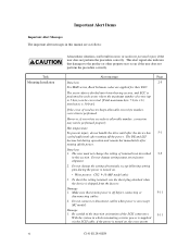
... the procedure correctly. Important Alert Items Important Alert Messages The important alert messages in this section. Hot temperature To prevent injury, do not handle the drive until after the device has 5-1 cooled sufficiently after turning off the power. Alert message Page Data loss 2-5 For MAN series, Reed Solomon codes are as...
... the procedure correctly. Important Alert Items Important Alert Messages The important alert messages in this section. Hot temperature To prevent injury, do not handle the drive until after the device has 5-1 cooled sufficiently after turning off the power. Alert message Page Data loss 2-5 For MAN series, Reed Solomon codes are as...
Manual/User Guide
Page 9
... shocks, turn the power off the power before requesting repair. Do not use solvents to clean a disk drive assembly. 5. Data loss 6-7 Save data stored on the disk drive before connecting or disconnecting a cable, connector, or plug. 2. Do not use a conductive cleaner to clean...drive, turn off before handling. Opening the disk enclosure in the wrong direction can be prevented. 2. Do not remove a PCA. Ribbon cables are used, inserting the cables in the field may cause the damage to ground before connecting or disconnecting a cable, connector, or plug. 3. Fujitsu...
... shocks, turn the power off the power before requesting repair. Do not use solvents to clean a disk drive assembly. 5. Data loss 6-7 Save data stored on the disk drive before connecting or disconnecting a cable, connector, or plug. 2. Do not use a conductive cleaner to clean...drive, turn off before handling. Opening the disk enclosure in the wrong direction can be prevented. 2. Do not remove a PCA. Ribbon cables are used, inserting the cables in the field may cause the damage to ground before connecting or disconnecting a cable, connector, or plug. 3. Fujitsu...
Manual/User Guide
Page 12
......5-11 5.6 Confirming Operations after Installation and Preparation for use 5-12 5.6.1 Confirming initial operations 5-12 5.6.2 Checking SCSI connection 5-13 5.6.3 Formatting ...5-16 5.6.4 Setting parameters ...5-18 5.7 Dismounting Drives...5-22 5.8 Spare Disk Drive ...5-22 CHAPTER 6 DIAGNOSTICS AND MAINTENANCE 6-1 6.1 Diagnostics ...6-1 6.1.1 Self-diagnostics ...6-1 6.1.2 Test programs ...6-4 6.2 Maintenance Information 6-5 6.2.1 Precautions ...6-5 6.2.2 Maintenance requirements 6-6 6.2.3 Maintenance levels ...6-8 6.2.4 Revision numbers ...6-9 6.2.5 Tools and test equipment...
......5-11 5.6 Confirming Operations after Installation and Preparation for use 5-12 5.6.1 Confirming initial operations 5-12 5.6.2 Checking SCSI connection 5-13 5.6.3 Formatting ...5-16 5.6.4 Setting parameters ...5-18 5.7 Dismounting Drives...5-22 5.8 Spare Disk Drive ...5-22 CHAPTER 6 DIAGNOSTICS AND MAINTENANCE 6-1 6.1 Diagnostics ...6-1 6.1.1 Self-diagnostics ...6-1 6.1.2 Test programs ...6-4 6.2 Maintenance Information 6-5 6.2.1 Precautions ...6-5 6.2.2 Maintenance requirements 6-6 6.2.3 Maintenance levels ...6-8 6.2.4 Revision numbers ...6-9 6.2.5 Tools and test equipment...
Manual/User Guide
Page 13
...12 Diagnostic test ...6-12 Troubleshooting Procedures 6-13 Outline of troubleshooting procedures 6-13 Troubleshooting with disk drive replacement in the field 6-13 Troubleshooting at the repair site 6-15 Troubleshooting with parts replacement in... (B-47-xx), (B-49-00), (B-4D-xx) and (B-4E-00): SCSI interface error 7-4 CHAPTER 8 PRINCIPLE OF OPERATION 8-1 8.1 Outline ...8-1 8.2 Disk Drive Configuration 8-1 8.2.1 Disks ...8-2 8.2.2 Heads ...8-2 8.2.3 Spindle mechanism...8-2 8.2.4 Actuator ...8-2 8.2.5 Air filters ...8-2 8.3 Circuit Configuration...8-3 8.4 Power-On Sequence ...8-5 8.5 ...
...12 Diagnostic test ...6-12 Troubleshooting Procedures 6-13 Outline of troubleshooting procedures 6-13 Troubleshooting with disk drive replacement in the field 6-13 Troubleshooting at the repair site 6-15 Troubleshooting with parts replacement in... (B-47-xx), (B-49-00), (B-4D-xx) and (B-4E-00): SCSI interface error 7-4 CHAPTER 8 PRINCIPLE OF OPERATION 8-1 8.1 Outline ...8-1 8.2 Disk Drive Configuration 8-1 8.2.1 Disks ...8-2 8.2.2 Heads ...8-2 8.2.3 Spindle mechanism...8-2 8.2.4 Actuator ...8-2 8.2.5 Air filters ...8-2 8.3 Circuit Configuration...8-3 8.4 Power-On Sequence ...8-5 8.5 ...
Manual/User Guide
Page 17
... settings (by CHANGE DEFINITION command 5-9 Table 5.8 Setting check list (MP model only 5-10 Table 6.1 Self-diagnostic functions...6-1 Table 6.2 System-level field troubleshooting 6-14 Table 6.3 Disk drive troubleshooting...6-15 Table 7.1 Definition of sense data...7-3 Table B.1 Setting terminal: CN2 ...B-2 Table C.1 SCSI connector (SCA2 type LVD 16-bit SCSI): CN1 C-2 Table C.2 SCSI connector (68...
... settings (by CHANGE DEFINITION command 5-9 Table 5.8 Setting check list (MP model only 5-10 Table 6.1 Self-diagnostic functions...6-1 Table 6.2 System-level field troubleshooting 6-14 Table 6.3 Disk drive troubleshooting...6-15 Table 7.1 Definition of sense data...7-3 Table B.1 Setting terminal: CN2 ...B-2 Table C.1 SCSI connector (SCA2 type LVD 16-bit SCSI): CN1 C-2 Table C.2 SCSI connector (68...
Manual/User Guide
Page 19
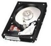
...Interface (SCSI), ANSI X3.131-1994: Small Computer System Interface - 2 (SCSI-2)]. IDDs are high performance large capacity 3.5 type fixed disk drives with large storage capacity. The flexibility and expandability of the SCSI, as well as the powerful command set of the intelligent disk... drives (IDD). C141-E128-01EN 1 - 1 CHAPTER 1 GENERAL DESCRIPTION 1.1 Standard Features 1.2 Hardware Structure 1.3 System Configuration This chapter describes the feature and...
...Interface (SCSI), ANSI X3.131-1994: Small Computer System Interface - 2 (SCSI-2)]. IDDs are high performance large capacity 3.5 type fixed disk drives with large storage capacity. The flexibility and expandability of the SCSI, as well as the powerful command set of the intelligent disk... drives (IDD). C141-E128-01EN 1 - 1 CHAPTER 1 GENERAL DESCRIPTION 1.1 Standard Features 1.2 Hardware Structure 1.3 System Configuration This chapter describes the feature and...
Manual/User Guide
Page 20
...logical specification of the SCSI CCS (Common Command Set for SCSI-2. This is extremely compact. For the ultra SCSI model, number of the disk drive. 1.1 Standard Features (1) Compactness Since the SCSI controller circuit is embedded in the standard 3.5 type fixed disk... drive form factor, the IDD is also available as follows. • 8-bit SCSI: 8 drives max. • 16-bit SCSI: 16 drives max. (4) High speed data transfer Such a high data transfer rate on the SCSI bus can ...
...logical specification of the SCSI CCS (Common Command Set for SCSI-2. This is extremely compact. For the ultra SCSI model, number of the disk drive. 1.1 Standard Features (1) Compactness Since the SCSI controller circuit is embedded in the standard 3.5 type fixed disk... drive form factor, the IDD is also available as follows. • 8-bit SCSI: 8 drives max. • 16-bit SCSI: 16 drives max. (4) High speed data transfer Such a high data transfer rate on the SCSI bus can ...
Manual/User Guide
Page 21
... perform the effective input/output operations with utilizing high data transfer capability of the SCSI bus regardless of actual data transfer rate of the disk drive. (7) Read-ahead cache feature After executing the READ command, the IDD reads automatically and stores (prefetches) the subsequent data blocks into the data buffer (Read...
... perform the effective input/output operations with utilizing high data transfer capability of the SCSI bus regardless of actual data transfer rate of the disk drive. (7) Read-ahead cache feature After executing the READ command, the IDD reads automatically and stores (prefetches) the subsequent data blocks into the data buffer (Read...
Manual/User Guide
Page 22
...capacity A large capacity can start and stop the spindle motor. (17) Diagnosis The IDD has a diagnostic capability which checks internal controller functions and drive operations to facilitate testing and repair. 1 - 4 C141-E128-01EN If a recoverable data check occurs, error-free data can be constructed in ...the IDD can automatically reassign its powerful retry processing. The initiator software is released from errors in SCSI bus or the disk drive using its alternate data block. (12) Programmable data block length Data can be transferred to recover from the complicated error recover...
...capacity A large capacity can start and stop the spindle motor. (17) Diagnosis The IDD has a diagnostic capability which checks internal controller functions and drive operations to facilitate testing and repair. 1 - 4 C141-E128-01EN If a recoverable data check occurs, error-free data can be constructed in ...the IDD can automatically reassign its powerful retry processing. The initiator software is released from errors in SCSI bus or the disk drive using its alternate data block. (12) Programmable data block length Data can be transferred to recover from the complicated error recover...

Manual/User Guide
Page 25
... rotated by a feedback circuit using the counter electromotive current to precisely maintain the speed at the end of the actuator arm is controlled by a direct-drive hall-less DC motor. The motor speed is controlled and positioned via feedback of the specified speed. (4) Actuator The actuator, which uses a rotary voice coil...
... rotated by a feedback circuit using the counter electromotive current to precisely maintain the speed at the end of the actuator arm is controlled by a direct-drive hall-less DC motor. The motor speed is controlled and positioned via feedback of the specified speed. (4) Actuator The actuator, which uses a rotary voice coil...
Manual/User Guide
Page 27
... LUN to select the peripheral device for the 16-bit SCSI in any combination. The IDD is constructed so that the whole volume of disk drive is possible on which multiple host computers that operate as logical unit. (1) SCSI bus configuration Up to eight SCSI devices operating as an initiator or...
... LUN to select the peripheral device for the 16-bit SCSI in any combination. The IDD is constructed so that the whole volume of disk drive is possible on which multiple host computers that operate as logical unit. (1) SCSI bus configuration Up to eight SCSI devices operating as an initiator or...
Manual/User Guide
Page 30
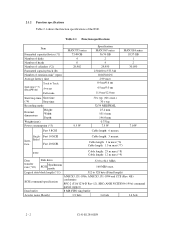
...32/34 MEEPRML 25.4 mm 101.6 mm 146.0 mm 0.75 kg 7.5 W Cable length: 6 m max MAN3184 series 18.37 GB 1 2 30,050 7.0 W Single- 2.1.2 Function specifications Table 2.1 shows the function specifications of rotations min-1 (rpm) Average latency ...: Depth: Weight (max) Power consumption (*5) Fast 5 SCSI MAN3735 series 73.49 GB 4 8 29,902 9.5 W Specification MAN3367 series 36.74 GB 2 4 29,950 230,400 to 528 byte (Fixed length) SCSI command specification...: 25 m max (*8) Cable length: 12 m max (*9) Data transfer rate (*10) Disk drive SCSI Synchronous mode 52.0 to 84.1 MB/s 160 MB/s max.
...32/34 MEEPRML 25.4 mm 101.6 mm 146.0 mm 0.75 kg 7.5 W Cable length: 6 m max MAN3184 series 18.37 GB 1 2 30,050 7.0 W Single- 2.1.2 Function specifications Table 2.1 shows the function specifications of rotations min-1 (rpm) Average latency ...: Depth: Weight (max) Power consumption (*5) Fast 5 SCSI MAN3735 series 73.49 GB 4 8 29,902 9.5 W Specification MAN3367 series 36.74 GB 2 4 29,950 230,400 to 528 byte (Fixed length) SCSI command specification...: 25 m max (*8) Cable length: 12 m max (*9) Data transfer rate (*10) Disk drive SCSI Synchronous mode 52.0 to 84.1 MB/s 160 MB/s max.

Manual/User Guide
Page 32
...) 1961.3m/s2 (200G) (2 ms) -60 m to 3,000 m -60 m to 12,000 m 0.6 A 0.45 A 0.4 A 3.0 A 0.9 A 0.7 A 0.4 A 0.9 A +5 V/+12 V 250 mVp-p 0.6 A (*1) For detail condition, see Section 4.1. (*2) Vibration applied to the drive is measured at near the mounting screw hole on the frame as much as possible. (*3) At random seek write/read and default on retry setting...
...) 1961.3m/s2 (200G) (2 ms) -60 m to 3,000 m -60 m to 12,000 m 0.6 A 0.45 A 0.4 A 3.0 A 0.9 A 0.7 A 0.4 A 0.9 A +5 V/+12 V 250 mVp-p 0.6 A (*1) For detail condition, see Section 4.1. (*2) Vibration applied to the drive is measured at near the mounting screw hole on the frame as much as possible. (*3) At random seek write/read and default on retry setting...
Manual/User Guide
Page 34
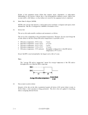
... environmental conditions, power trouble, host system trouble, cable failures, or other failures not caused by a well-trained service mechanic to diagnose and repair a drive malfunction. Note: The "average DE surface temperature" means the average temperature at the DE surface throughout the year when the IDD is operating. (4) Data...: 46°C to 50°C • DE surface temperature: 51°C to formatting disks or assigning alternate blocks. 2 - 6 C141-E035-02EN The drive is designed for a MTTR of the equipment means failure that DE surface temperature is as follows.
... environmental conditions, power trouble, host system trouble, cable failures, or other failures not caused by a well-trained service mechanic to diagnose and repair a drive malfunction. Note: The "average DE surface temperature" means the average temperature at the DE surface throughout the year when the IDD is operating. (4) Data...: 46°C to 50°C • DE surface temperature: 51°C to formatting disks or assigning alternate blocks. 2 - 6 C141-E035-02EN The drive is designed for a MTTR of the equipment means failure that DE surface temperature is as follows.

Manual/User Guide
Page 41
Cell Note: This drive manages alternate spare areas for each cell, which is a set of the user space is allocated as alternate cylinders as the number of spare sectors ...
Cell Note: This drive manages alternate spare areas for each cell, which is a set of the user space is allocated as alternate cylinders as the number of spare sectors ...

Manual/User Guide
Page 46
... of the zone except alternate cylinders in cells in the alternate cylinders. 3.2 Logical Data Block Addressing Independently of the physical structure of the disk drive, the IDD adopts the logical data block addressing as in logical data block units. The IDD relates a logical data block address to be accessed... length MAN3735 series 8 MAN3367 series 4 512 MAN3184 series 2 User blocks 143,550,456 71,771,688 35,885,448 Format capacity (GB) 73.49 36.74 18.37 Note: Total number of spare sectors is calculated by adding the number of spare sectors in each primary cylinder and the...
... of the zone except alternate cylinders in cells in the alternate cylinders. 3.2 Logical Data Block Addressing Independently of the physical structure of the disk drive, the IDD adopts the logical data block addressing as in logical data block units. The IDD relates a logical data block address to be accessed... length MAN3735 series 8 MAN3367 series 4 512 MAN3184 series 2 User blocks 143,550,456 71,771,688 35,885,448 Format capacity (GB) 73.49 36.74 18.37 Note: Total number of spare sectors is calculated by adding the number of spare sectors in each primary cylinder and the...

Manual/User Guide
Page 47
...Growth defect list): This list consists of defective logical data block location information specified in a REASSIGN BLOCKS command by the INIT, information on the disk drive. C141-E128-01EN 3 - 11 The INIT can read out the contents of the P and G lists by the READ DEFECT DATA command. 3.3.2 ... area explicitly. 3.3 Defect Management 3.3.1 Defect list Information of the defect location on the disk is recorded in the system space of the disk drive as the C list. When the logical data block is allocated, some sectors (track skew and cylinder skew) shown in Figure 3.5 are provided...
...Growth defect list): This list consists of defective logical data block location information specified in a REASSIGN BLOCKS command by the INIT, information on the disk drive. C141-E128-01EN 3 - 11 The INIT can read out the contents of the P and G lists by the READ DEFECT DATA command. 3.3.2 ... area explicitly. 3.3 Defect Management 3.3.1 Defect list Information of the defect location on the disk is recorded in the system space of the disk drive as the C list. When the logical data block is allocated, some sectors (track skew and cylinder skew) shown in Figure 3.5 are provided...

