Manual/User Guide
Page 5
..., and system configuration. Chapter 8 PRINCIPLE OF OPERATION This chapter explains disk drives configuration and operation of MAN series disk drive. C141-E128-01EN iii The need arises, use in details how collect the information for installing MAN series disk drives. PREFACE This manual describes the MAN3735MC/MP, MAN3367MC/MP, MAN3184MC/MP (hereafter, MAN series), 3.5 type fixed disk drives with an embedded SCSI controller. Chapter 2 SPECIFICATIONS This chapter gives detailed specifications of fixed disk drives and their use the other...
..., and system configuration. Chapter 8 PRINCIPLE OF OPERATION This chapter explains disk drives configuration and operation of MAN series disk drive. C141-E128-01EN iii The need arises, use in details how collect the information for installing MAN series disk drives. PREFACE This manual describes the MAN3735MC/MP, MAN3367MC/MP, MAN3184MC/MP (hereafter, MAN series), 3.5 type fixed disk drives with an embedded SCSI controller. Chapter 2 SPECIFICATIONS This chapter gives detailed specifications of fixed disk drives and their use the other...
Manual/User Guide
Page 7
Hand Disk Drive Type AN: Number of the SCSI, i.e., the interface for drive failures caused by misuse by the user, poor environmental conditions, power trouble, host problems, cable failures, or any failure not caused by the drive itself. Note 1: Model names M AN 3 735 MC Interface types MC: LVD, 16-bit SCSI SCA2 connector 160MHz transfer MP: LVD, 16-bit SCSI 68 pin connector 160MHz transfer Formatted capacity (100 MB units) Disk drive size 3: 3.5 type. Fujitsu is . The suffix of the model name of the disk drive varies...
Hand Disk Drive Type AN: Number of the SCSI, i.e., the interface for drive failures caused by misuse by the user, poor environmental conditions, power trouble, host problems, cable failures, or any failure not caused by the drive itself. Note 1: Model names M AN 3 735 MC Interface types MC: LVD, 16-bit SCSI SCA2 connector 160MHz transfer MP: LVD, 16-bit SCSI 68 pin connector 160MHz transfer Formatted capacity (100 MB units) Disk drive size 3: 3.5 type. Fujitsu is . The suffix of the model name of the disk drive varies...
Manual/User Guide
Page 8
... sector-data is divided into 6 interleaving sectors, and ECC is performed in each sector where the maximum number of the SCSI connectors. 5-11 With the system in which terminating resistor power is supplied via the SCSI cable, if the power is off the power. To short the setting terminal, use the short plug attached when the device is on , the overcurrent vi C141-E128-01EN Do not change...
... sector-data is divided into 6 interleaving sectors, and ECC is performed in each sector where the maximum number of the SCSI connectors. 5-11 With the system in which terminating resistor power is supplied via the SCSI cable, if the power is off the power. To short the setting terminal, use the short plug attached when the device is on , the overcurrent vi C141-E128-01EN Do not change...
Manual/User Guide
Page 14
... format...8-12 Spindle motor control ...8-12 Voice coil motor control 8-13 APPENDIX A LOCATIONS OF CONNECTORS AND SETTING TERMINALS A-1 A.1 Locations of Connectors and Setting Terminals (MAH series MC model A-2 A.2 Locations of Connectors and Setting Terminals (MAN series MP model A-3 APPENDIX B SETTING TERMINALS B-1 B.1 Setting Terminals (MP model only B-2 APPENDIX C CONNECTOR SIGNAL ALLOCATION C-1 C.1 SCSI Connector Signal Allocation: SCA2 type LVD 16-bit SCSI C-2 C.2 SCSI Connector Signal Allocation: 68 pin type LVD 16-bit SCSI C-3 APPENDIX D MODEL NAMES AND PRODUCT NUMBERS...
... format...8-12 Spindle motor control ...8-12 Voice coil motor control 8-13 APPENDIX A LOCATIONS OF CONNECTORS AND SETTING TERMINALS A-1 A.1 Locations of Connectors and Setting Terminals (MAH series MC model A-2 A.2 Locations of Connectors and Setting Terminals (MAN series MP model A-3 APPENDIX B SETTING TERMINALS B-1 B.1 Setting Terminals (MP model only B-2 APPENDIX C CONNECTOR SIGNAL ALLOCATION C-1 C.1 SCSI Connector Signal Allocation: SCA2 type LVD 16-bit SCSI C-2 C.2 SCSI Connector Signal Allocation: 68 pin type LVD 16-bit SCSI C-3 APPENDIX D MODEL NAMES AND PRODUCT NUMBERS...
Manual/User Guide
Page 17
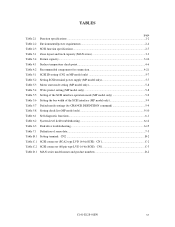
... Setting SCSI terminal power supply (MP model only 5-7 Table 5.3 Motor start mode setting (MP model only 5-8 Table 5.4 Write protect setting (MP model only 5-8 Table 5.5 Setting of the SCSI interface operation mode (MP model only 5-9 Table 5.6 Setting the bus width of the SCSI interface (MP model only 5-9 Table 5.7 Default mode settings (by CHANGE DEFINITION command 5-9 Table 5.8 Setting check list (MP model only 5-10 Table 6.1 Self-diagnostic functions...6-1 Table 6.2 System-level field troubleshooting 6-14 Table 6.3 Disk drive troubleshooting...6-15 Table 7.1 Definition of sense data...
... Setting SCSI terminal power supply (MP model only 5-7 Table 5.3 Motor start mode setting (MP model only 5-8 Table 5.4 Write protect setting (MP model only 5-8 Table 5.5 Setting of the SCSI interface operation mode (MP model only 5-9 Table 5.6 Setting the bus width of the SCSI interface (MP model only 5-9 Table 5.7 Default mode settings (by CHANGE DEFINITION command 5-9 Table 5.8 Setting check list (MP model only 5-10 Table 6.1 Self-diagnostic functions...6-1 Table 6.2 System-level field troubleshooting 6-14 Table 6.3 Disk drive troubleshooting...6-15 Table 7.1 Definition of sense data...
Manual/User Guide
Page 30
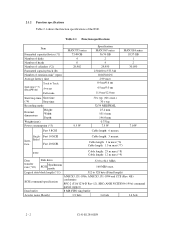
... m max (*9) Data transfer rate (*10) Disk drive SCSI Synchronous mode 52.0 to 528 byte (Fixed length) SCSI command specification ANSI X3.131-1986, ANSI X3.131-1994 and CCS (Rev. 4B) conformity SPC-2 (T10/1236-D Rev 12), SBC (ANSI NCITS306-199x) command partial support Data buffer 8 MB FIFO ring buffer Acostic noise (Ready) 3.9 bels 3.6 bels 3.6 bels 2 - 2 C141-E128-01EN Table 2.1 Function specifications Item Formatted capacity/device (*1) Number of disks Number of heads Number...
... m max (*9) Data transfer rate (*10) Disk drive SCSI Synchronous mode 52.0 to 528 byte (Fixed length) SCSI command specification ANSI X3.131-1986, ANSI X3.131-1994 and CCS (Rev. 4B) conformity SPC-2 (T10/1236-D Rev 12), SBC (ANSI NCITS306-199x) command partial support Data buffer 8 MB FIFO ring buffer Acostic noise (Ready) 3.9 bels 3.6 bels 3.6 bels 2 - 2 C141-E128-01EN Table 2.1 Function specifications Item Formatted capacity/device (*1) Number of disks Number of heads Number...
Manual/User Guide
Page 31
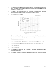
... 1 connection case. (*9) 1 host, 15 devices case. (*10) The maximum data transfer rate may be changed by transmission characteristics. (*11) The terminator power pin (SCSI connector) which supplies power to the response speed of initiator and by changing the logical block length and using spare sector space. See Chapter 3 for 512 bytes per sector. (*2) The number of user cylinders indicates the max., and includes the alternate cylinder. (*1) The formatted capacity can use cable length of up to 3.0 m. (*7) 5 to 8 SCSI devices having...
... 1 connection case. (*9) 1 host, 15 devices case. (*10) The maximum data transfer rate may be changed by transmission characteristics. (*11) The terminator power pin (SCSI connector) which supplies power to the response speed of initiator and by changing the logical block length and using spare sector space. See Chapter 3 for 512 bytes per sector. (*2) The number of user cylinders indicates the max., and includes the alternate cylinder. (*1) The formatted capacity can use cable length of up to 3.0 m. (*7) 5 to 8 SCSI devices having...
Manual/User Guide
Page 33
... The number of read sector keeps allowable error byte number, correction is performed in the error rate. CAUTION Data loss For MAN series, Reed Solomon codes are specified at all field sites C141-E128-01EN 2 - 5 The sector-data is divided into 6 interleaving sectors, and ECC is performed. Data blocks to be accessed should not exceed 1 per 108 seeks. 2.1.5 Reliability (1) Mean Time Between Failures (MTBF) MTBF of the IDD during initialization and replaced by...
... The number of read sector keeps allowable error byte number, correction is performed in the error rate. CAUTION Data loss For MAN series, Reed Solomon codes are specified at all field sites C141-E128-01EN 2 - 5 The sector-data is divided into 6 interleaving sectors, and ECC is performed. Data blocks to be accessed should not exceed 1 per 108 seeks. 2.1.5 Reliability (1) Mean Time Between Failures (MTBF) MTBF of the IDD during initialization and replaced by...
Manual/User Guide
Page 34
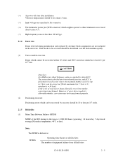
... operating. (4) Data security at power failure Integrity of the data on the disk is guaranteed against all forms of DC power failure except on the environment temperature. Mishandling by the operator, failures due to bad environmental conditions, power trouble, host system trouble, cable failures, or other failures not caused by the equipment are not considered. (2) Mean Time To Repair (MTTR) MTTR is the average time taken by a well-trained service mechanic to formatting disks...
... operating. (4) Data security at power failure Integrity of the data on the disk is guaranteed against all forms of DC power failure except on the environment temperature. Mishandling by the operator, failures due to bad environmental conditions, power trouble, host system trouble, cable failures, or other failures not caused by the equipment are not considered. (2) Mean Time To Repair (MTTR) MTTR is the average time taken by a well-trained service mechanic to formatting disks...
Manual/User Guide
Page 59
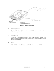
... to near the ferromagnetic body like a speaker to achieve a high speed seek. [Surface P'] • Setting terminal (MP model only) • External operator panel connector [Surface P] • Cable connection [Surface R] • Hole for mounting screw [Surface Q] • Hole for mounting screw Figure 4.7 Service clearance area (6) External magnetic field The drive should not be installed near equipment. (8) Others Seals on the DE prevent the DE...
... to near the ferromagnetic body like a speaker to achieve a high speed seek. [Surface P'] • Setting terminal (MP model only) • External operator panel connector [Surface P] • Cable connection [Surface R] • Hole for mounting screw [Surface Q] • Hole for mounting screw Figure 4.7 Service clearance area (6) External magnetic field The drive should not be installed near equipment. (8) Others Seals on the DE prevent the DE...
Manual/User Guide
Page 75
... plugs, mounting drives, connecting cables, confirming drive operations after installation and preparation for setting. CAUTION Hot temperature To prevent injury, do not handle the drive until after the device has cooled sufficiently after turning off the power. b) Do not leave the drive in a dirty or contaminated environment. CHAPTER 5 INSTALLATION 5.1 Notes on Handling Drives 5.2 Connections 5.3 Setting Terminals 5.4 Mounting Drives 5.5 Connecting Cables 5.6 Confirming Operations after Installation and Preparation for Use 5.7 Dismounting Drives 5.8 Spare Disk Drive This chapter...
... plugs, mounting drives, connecting cables, confirming drive operations after installation and preparation for setting. CAUTION Hot temperature To prevent injury, do not handle the drive until after the device has cooled sufficiently after turning off the power. b) Do not leave the drive in a dirty or contaminated environment. CHAPTER 5 INSTALLATION 5.1 Notes on Handling Drives 5.2 Connections 5.3 Setting Terminals 5.4 Mounting Drives 5.5 Connecting Cables 5.6 Confirming Operations after Installation and Preparation for Use 5.7 Dismounting Drives 5.8 Spare Disk Drive This chapter...
Manual/User Guide
Page 76
... "Handle With Care" on hard material such as those at delivery, use one of the DE and screws. (3) Installation/removal/replacement a) Do not attempt to the internal unit when removing cushions. (2) Unpackaging a) Use a flat work for replacing. (4) Packaging a) Store the drive in an antistatic vinyl pack. In this case, fully protect the PCAs and interface connector so that may be used, use the same cushions and...
... "Handle With Care" on hard material such as those at delivery, use one of the DE and screws. (3) Installation/removal/replacement a) Do not attempt to the internal unit when removing cushions. (2) Unpackaging a) Use a flat work for replacing. (4) Packaging a) Store the drive in an antistatic vinyl pack. In this case, fully protect the PCAs and interface connector so that may be used, use the same cushions and...
Manual/User Guide
Page 90
... mode. 5.6.3 Formatting Since the disk drive is formatted with a specific (default) data format for a recoverable error. The user can be obtained with the MODE SELECT or MODE SELECT EXTENDED command. Refer to Chapter 5 of SCSI Logical Interface Specifications for the SCSI cable connection: • All connectors including other SCSI devices are as follows. To explicitly specify the number of logical data blocks, specify the number in "number of data blocks" field. Refer to Chapters 3 and 6 of SCSI Logical Interface Specifications for further details. (1) MODE SELECT/MODE SELECT...
... mode. 5.6.3 Formatting Since the disk drive is formatted with a specific (default) data format for a recoverable error. The user can be obtained with the MODE SELECT or MODE SELECT EXTENDED command. Refer to Chapter 5 of SCSI Logical Interface Specifications for the SCSI cable connection: • All connectors including other SCSI devices are as follows. To explicitly specify the number of logical data blocks, specify the number in "number of data blocks" field. Refer to Chapters 3 and 6 of SCSI Logical Interface Specifications for further details. (1) MODE SELECT/MODE SELECT...
Manual/User Guide
Page 92
... command: • Error recovery parameter • Disconnection/reconnection parameter • Caching parameter • Control mode parameter With the MODE SELECT or MODE SELECT EXTENDED command, specify 1 for each SCSI ID of the IDD, the saving operation for all IDs. At factory shipment of but as next saving operation is not saved for each INIT. 3. IMPORTANT 1. The model select parameter is executed from the INIT. When the parameters are not set or saved with the default...
... command: • Error recovery parameter • Disconnection/reconnection parameter • Caching parameter • Control mode parameter With the MODE SELECT or MODE SELECT EXTENDED command, specify 1 for each SCSI ID of the IDD, the saving operation for all IDs. At factory shipment of but as next saving operation is not saved for each INIT. 3. IMPORTANT 1. The model select parameter is executed from the INIT. When the parameters are not set or saved with the default...
Manual/User Guide
Page 94
... use the default setting in normal operations. (2) Disconnection/reconnection parameters (page code = 2) The following parameters according to be specified. 2. The user also can arbitrarily specify the following parameters are used to optimize the start timing of reconnection processing to transfer data on the SCSI bus at a read (READ or READ EXTENDED command) or write operation (WRITE, WRITE EXTENDED, or WRITE AND VERIFY command) of the specified values by measuring performance in consideration of the following performance...
... use the default setting in normal operations. (2) Disconnection/reconnection parameters (page code = 2) The following parameters according to be specified. 2. The user also can arbitrarily specify the following parameters are used to optimize the start timing of reconnection processing to transfer data on the SCSI bus at a read (READ or READ EXTENDED command) or write operation (WRITE, WRITE EXTENDED, or WRITE AND VERIFY command) of the specified values by measuring performance in consideration of the following performance...
Manual/User Guide
Page 103
... servicing or repair. Contact Fujitsu representative to submit information for the disk drive. C141-E128-01EN 6 - 7 (3) Parts that can be replaced in the field The PCA cannot be included: a) IDD model, part number (P/N), revision number, serial number (S/N), and date of manufacturing b) Error status • Date when the error occurred • System configuration • Environmental conditions (temperature, humidity, and voltage) c) Error history d) Error contents • Outline of inconvenience • Issued commands and specified parameters • Sense data...
... servicing or repair. Contact Fujitsu representative to submit information for the disk drive. C141-E128-01EN 6 - 7 (3) Parts that can be replaced in the field The PCA cannot be included: a) IDD model, part number (P/N), revision number, serial number (S/N), and date of manufacturing b) Error status • Date when the error occurred • System configuration • Environmental conditions (temperature, humidity, and voltage) c) Error history d) Error contents • Outline of inconvenience • Issued commands and specified parameters • Sense data...
Manual/User Guide
Page 110
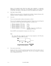
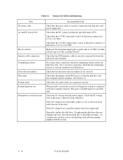
... troubleshooting Item DC power cable AC and DC power level Electrical noise Interface cable connection Terminating resistors Drive selection address Plug setup System cables System diagnostic test Intermittent or nonfatal errors Recommended work Check that the terminating resistor is correctly mounted on all system cables are set correctly. For a star-burst connection, check that the power cable is correctly connected to the disk drive and power supply unit. This gives a detailed report of the power connector) is set...
... troubleshooting Item DC power cable AC and DC power level Electrical noise Interface cable connection Terminating resistors Drive selection address Plug setup System cables System diagnostic test Intermittent or nonfatal errors Recommended work Check that the terminating resistor is correctly mounted on all system cables are set correctly. For a star-burst connection, check that the power cable is correctly connected to the disk drive and power supply unit. This gives a detailed report of the power connector) is set...
Manual/User Guide
Page 111
... used. CAUTION Never open the disk enclosure in the field may cause an irreparable fault. C141-E128-01EN 6 - 15 To check performance, change the disk drive conditions by sense data, and gives supplementary information on finding the error cause (faulty part). If the possibly faulty part is correct. If the detected error cannot be recreated in the disk enclosure, return the whole disk drive to the factory for repair. Replace the disk drive...
... used. CAUTION Never open the disk enclosure in the field may cause an irreparable fault. C141-E128-01EN 6 - 15 To check performance, change the disk drive conditions by sense data, and gives supplementary information on finding the error cause (faulty part). If the possibly faulty part is correct. If the detected error cannot be recreated in the disk enclosure, return the whole disk drive to the factory for repair. Replace the disk drive...
Manual/User Guide
Page 129
... moves the head to the reference cylinder (cylinder 0) by an internal command from the MPU. (2) Seek operation When the host issues a data read or write data from or to maintain the detected rotational speed. 8.7.5 Voice coil motor control The voice coil motor is used depending on the specific data side. The MPU controls the controller to a disk, the head must be correctly centered over the target cylinder. The digital servo control circuit controls the...
... moves the head to the reference cylinder (cylinder 0) by an internal command from the MPU. (2) Seek operation When the host issues a data read or write data from or to maintain the detected rotational speed. 8.7.5 Voice coil motor control The voice coil motor is used depending on the specific data side. The MPU controls the controller to a disk, the head must be correctly centered over the target cylinder. The digital servo control circuit controls the...
Manual/User Guide
Page 136
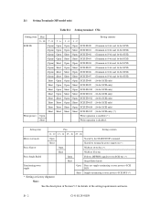
... Short Open Short SCSI ID #13 (16-bit SCSI only) Short Short Short Open SCSI ID #14 (16-bit SCSI only) Short Short Short Short SCSI ID #15 (16-bit SCSI only) (*) Write protect Open Write operation is enabled. (*) Short Write operation is disabled. Setting item Pins Setting contents 11 - 12 13 - 14 15 - 16 23 - 24 Motor start mode Open Started by the START/STOP command Short Started by turning the power supply...
... Short Open Short SCSI ID #13 (16-bit SCSI only) Short Short Short Open SCSI ID #14 (16-bit SCSI only) Short Short Short Short SCSI ID #15 (16-bit SCSI only) (*) Write protect Open Write operation is enabled. (*) Short Write operation is disabled. Setting item Pins Setting contents 11 - 12 13 - 14 15 - 16 23 - 24 Motor start mode Open Started by the START/STOP command Short Started by turning the power supply...


