Operation Manual
Page 6
v This scanner features duplex scanning and high quality color image processing with an automatic document feeder (ADF). The fi-4750C is a highly functional color image scanner developed for basic information about the fi-4750C. Refer to clean and maintain the fi-4750C image scanner. Preface This manual explains how to the Operator's Guide for volume filing, using charge-coupled device (CCD) color image sensors.
v This scanner features duplex scanning and high quality color image processing with an automatic document feeder (ADF). The fi-4750C is a highly functional color image scanner developed for basic information about the fi-4750C. Refer to clean and maintain the fi-4750C image scanner. Preface This manual explains how to the Operator's Guide for volume filing, using charge-coupled device (CCD) color image sensors.

Operation Manual
Page 15
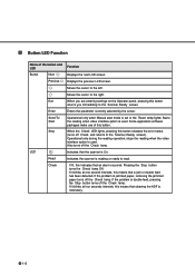
Send To Start Starts the reading. while Manual start mode is set or the Read lamp lights when the video interface option is used . Stop When the Check LED lights, pressing this button returns you are entering settings on the Operator panel, pressing this button releases the error status (turns off Check and returns to the Scanner Ready screen). Pressing the Stop button turns the Check lamp off the Check lamp. Check If lit, indicates an alarm occurred. Panel Display Button/LED Function...
Send To Start Starts the reading. while Manual start mode is set or the Read lamp lights when the video interface option is used . Stop When the Check LED lights, pressing this button returns you are entering settings on the Operator panel, pressing this button releases the error status (turns off Check and returns to the Scanner Ready screen). Pressing the Stop button turns the Check lamp off the Check lamp. Check If lit, indicates an alarm occurred. Panel Display Button/LED Function...

Operation Manual
Page 18
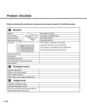
See Chapter 4 for removing jammed ducuments. Check the document and re-scan it. 1-9 Fill the ADF paper chute with paper. This message is displayed if the ADF is displayed when the ADF detects a Double feed error. This message is not closed completely. To enable the read operation. Close the ADF completely, and enable the read operation, press the stop button. This message is displayed if a document is no more paper on the ADF paper chute during a read operation in the ADF. DESCRIPTION Temporary error This message is displayed if there is jammed in ADF mode.
See Chapter 4 for removing jammed ducuments. Check the document and re-scan it. 1-9 Fill the ADF paper chute with paper. This message is displayed if the ADF is displayed when the ADF detects a Double feed error. This message is not closed completely. To enable the read operation. Close the ADF completely, and enable the read operation, press the stop button. This message is displayed if a document is no more paper on the ADF paper chute during a read operation in the ADF. DESCRIPTION Temporary error This message is displayed if there is jammed in ADF mode.

Operation Manual
Page 44
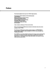
NO Did you load the paper on the operator panel. YES Extend the time for at least 10 seconds. NO Have 10 seconds passed since the scanner was last used? YES Contact the manufacturer's authorized service center. 4-4 NO Did the scanner enter this state quickly? YES Wait for entering "Low Power Mode" in Set Up Mode. YES Load the paper again, or press any button on the operator panel to wake up the system. Power "On" Has it been a long time since the PC instructed a scan? 2 Symptom The operator panel turns "Off". YES Press any button on the ADF?
NO Did you load the paper on the operator panel. YES Extend the time for at least 10 seconds. NO Have 10 seconds passed since the scanner was last used? YES Contact the manufacturer's authorized service center. 4-4 NO Did the scanner enter this state quickly? YES Wait for entering "Low Power Mode" in Set Up Mode. YES Load the paper again, or press any button on the operator panel to wake up the system. Power "On" Has it been a long time since the PC instructed a scan? 2 Symptom The operator panel turns "Off". YES Press any button on the ADF?

Operation Manual
Page 46
NO Is the scanner the last device of the NO system 4800 bps? (When you use the Fujitsu video interface board.) YES YES Is the CHECK indicator lit? NO Set the SCSI ID correctly. Contact the manufacturer's authorized service center to set correctly? Use the operator panel to Symptom 6. (See p. 4-9) NO Contact the manufacturer's authorized service center. 4-6 CHECK Is an Alarm displayed? YES Is the baud rate of the SCSI chain? The termination should be turned off via the front panel. Refer to change the ID. YES Is the SCSI ID set the correct baud rate.
NO Is the scanner the last device of the NO system 4800 bps? (When you use the Fujitsu video interface board.) YES YES Is the CHECK indicator lit? NO Set the SCSI ID correctly. Contact the manufacturer's authorized service center to set correctly? Use the operator panel to Symptom 6. (See p. 4-9) NO Contact the manufacturer's authorized service center. 4-6 CHECK Is an Alarm displayed? YES Is the baud rate of the SCSI chain? The termination should be turned off via the front panel. Refer to change the ID. YES Is the SCSI ID set the correct baud rate.
Operation Manual
Page 60
Image error Interface controller model Software/application name Can you send the original and output of sheet by facsimile or by the double line. Error status Transport error Type of the back. This example shows the revision A2. 4-20 What is printed on the label located at the left corner of document. The revision is indicated by mail? (Example) fi-4750C (Example) CA02956-2352 (Example) 00002...
Image error Interface controller model Software/application name Can you send the original and output of sheet by facsimile or by the double line. Error status Transport error Type of the back. This example shows the revision A2. 4-20 What is printed on the label located at the left corner of document. The revision is indicated by mail? (Example) fi-4750C (Example) CA02956-2352 (Example) 00002...
Operating Guide
Page 7
... document feeder (ADF). Preface This manual explains how to the Cleaning and Maintenance Guide for high quality color image processing, using charge-coupled device (CCD) color image sensors. This manual contains chapters on OPERATING INSTRUCTIONS, CLEANING, REPLACEMENT OF PARTS, ADJUSTMENT and TROUBLESHOOTING. The Cleaning and Maintenance Guide contains chapters on the following topics: COMPONENTS INSTALLATION AND CONNECTIONS OPERATING INSTRUCTIONS ADF DOCUMENT SPECIFICATIONS SCANNER SPECFICATIONS CONSUMABLES AND OPTIONS SETUP MODE It also contains a Glossary of the fi-4750C...
... document feeder (ADF). Preface This manual explains how to the Cleaning and Maintenance Guide for high quality color image processing, using charge-coupled device (CCD) color image sensors. This manual contains chapters on OPERATING INSTRUCTIONS, CLEANING, REPLACEMENT OF PARTS, ADJUSTMENT and TROUBLESHOOTING. The Cleaning and Maintenance Guide contains chapters on the following topics: COMPONENTS INSTALLATION AND CONNECTIONS OPERATING INSTRUCTIONS ADF DOCUMENT SPECIFICATIONS SCANNER SPECFICATIONS CONSUMABLES AND OPTIONS SETUP MODE It also contains a Glossary of the fi-4750C...

Operating Guide
Page 9
...INSTRUCTION Turning the Power On 3-1 Waking up the Scanner from the Low Power Mode 3-2 Manual Feed Mode Setting 3-3 Loading Documents on the ADF 3-4 Loading Documents on the Flatbed 3-8 Loading Documents Larger than the Document Bed 3-9 Reading a Page from a Thick Book 3-10 u CHAPTER 4 ADF DOCUMENT SPECIFICATION Document Size ...4-1 Document Quality 4-2 ADF Document Feeder Capacity 4-4 Areas not to be Perforated 4-5 Grounding Color Areas 4-6 Double Feed Detection Condition 4-7 Job Separation Sheet 4-8 u CHAPTER 5 SCANNER SPECIFICATIONS Basic Product Specification 5-1 Installation...
...INSTRUCTION Turning the Power On 3-1 Waking up the Scanner from the Low Power Mode 3-2 Manual Feed Mode Setting 3-3 Loading Documents on the ADF 3-4 Loading Documents on the Flatbed 3-8 Loading Documents Larger than the Document Bed 3-9 Reading a Page from a Thick Book 3-10 u CHAPTER 4 ADF DOCUMENT SPECIFICATION Document Size ...4-1 Document Quality 4-2 ADF Document Feeder Capacity 4-4 Areas not to be Perforated 4-5 Grounding Color Areas 4-6 Double Feed Detection Condition 4-7 Job Separation Sheet 4-8 u CHAPTER 5 SCANNER SPECIFICATIONS Basic Product Specification 5-1 Installation...

Operating Guide
Page 14
This section also provides the name of the scanner. Refer to the operating position before the scanner can be switched to page 2-4. 1-2 Units 1 Document cover 4 Automatic document feeder (ADF) 3 Document holding pad 2 Document bed 5 Stacker 7 Operator panel 8 ADF paper chute 9 ADF lever 12 Third party slot 6 Power switch 11 Interface connector 10 Power inlet fi-4750C NOTICE The shipping lock must be used. Units and Assemblies This section shows the exterior view and assemblies of each part and describes its functions.
This section also provides the name of the scanner. Refer to the operating position before the scanner can be switched to page 2-4. 1-2 Units 1 Document cover 4 Automatic document feeder (ADF) 3 Document holding pad 2 Document bed 5 Stacker 7 Operator panel 8 ADF paper chute 9 ADF lever 12 Third party slot 6 Power switch 11 Interface connector 10 Power inlet fi-4750C NOTICE The shipping lock must be used. Units and Assemblies This section shows the exterior view and assemblies of each part and describes its functions.

Operating Guide
Page 15
Part 1 Document cover 2 Document bed 3 Document holding pad 4 Automatic document feeder (ADF) 5 Stacker 6 Power switch 7 Operator panel 8 ADF paper chute 9 ADF lever 10 Power inlet 11 Interface connectors 12 Third party slot Function Closes over and keeps in the feeder. Holds document to be read documents. Also called Flatbed (FB). Automatically feeds documents to be read. Holds the documents to the reading position. No. Contains indicator panel that indicates scanner status. Connects to an AC power outlet with interface cables. Connects to...
Part 1 Document cover 2 Document bed 3 Document holding pad 4 Automatic document feeder (ADF) 5 Stacker 6 Power switch 7 Operator panel 8 ADF paper chute 9 ADF lever 10 Power inlet 11 Interface connectors 12 Third party slot Function Closes over and keeps in the feeder. Holds document to be read documents. Also called Flatbed (FB). Automatically feeds documents to be read. Holds the documents to the reading position. No. Contains indicator panel that indicates scanner status. Connects to an AC power outlet with interface cables. Connects to...
Operating Guide
Page 18
.... If the problem is double feed, pressing the Stop button turns off the Check lamp. Moves the cursor to the left. If the problem is jammed paper, removing the jammed paper turns off the Check lamp. Previous Displays the previous LCD screen. Read Indicates the scanner is used . Exit When you immediately to the Scanner Ready screen. Some application software packages make use of the button and LED Function Button Next Displays the next LCD screen. Starts the reading...
.... If the problem is double feed, pressing the Stop button turns off the Check lamp. Moves the cursor to the left. If the problem is jammed paper, removing the jammed paper turns off the Check lamp. Previous Displays the previous LCD screen. Read Indicates the scanner is used . Exit When you immediately to the Scanner Ready screen. Some application software packages make use of the button and LED Function Button Next Displays the next LCD screen. Starts the reading...
Operating Guide
Page 27
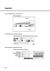
Inspection This section describes how to which this scanner conforms. Label B (Example; your actual label may differ) Indicates product information as follows: Model name Specification number Serial number Production date Weight MODEL fi-4750C PART NO. Label A 0123456789 B 0123456789 C 0123456789 * M 4 0 9 7 D 0 0 0 0 0 3* MADE IN JAPAN ANS 2-2 Position of two labels Label A Label B Label A (Example; your actual label may differ) Indicates regulations and standards to check the labels. NO. 000001 DATE 2000-11 22 Kg FUJITSU LIMITED Rev. CAO2956 -2362 SER.
Inspection This section describes how to which this scanner conforms. Label B (Example; your actual label may differ) Indicates product information as follows: Model name Specification number Serial number Production date Weight MODEL fi-4750C PART NO. Label A 0123456789 B 0123456789 C 0123456789 * M 4 0 9 7 D 0 0 0 0 0 3* MADE IN JAPAN ANS 2-2 Position of two labels Label A Label B Label A (Example; your actual label may differ) Indicates regulations and standards to check the labels. NO. 000001 DATE 2000-11 22 Kg FUJITSU LIMITED Rev. CAO2956 -2362 SER.

Operating Guide
Page 56
... Specification Remarks 1 Operating method ADF (Duplex), Flatbed 2 Image sensor CCD x 2 Front/Back 3 Light source LED Lamp x 2 Green, Red, Blue 4 Document Size Minimum A8 (Portrait) Maximum A3/Double Letter 5 Document ...slow. The usage with NO COMPRESSION is recommended. *6: Both SCSI-2 and the Third Party Slot can not be used at the host computer. *4: The maximum number will differ due to chapter 4. *5: The scanning speed might differ due to host computers' environment. *3: These speeds do not contain processing time at the same time. *7: The Power consumption of ADF...
... Specification Remarks 1 Operating method ADF (Duplex), Flatbed 2 Image sensor CCD x 2 Front/Back 3 Light source LED Lamp x 2 Green, Red, Blue 4 Document Size Minimum A8 (Portrait) Maximum A3/Double Letter 5 Document ...slow. The usage with NO COMPRESSION is recommended. *6: Both SCSI-2 and the Third Party Slot can not be used at the host computer. *4: The maximum number will differ due to chapter 4. *5: The scanning speed might differ due to host computers' environment. *3: These speeds do not contain processing time at the same time. *7: The Power consumption of ADF...

Operating Guide
Page 71
... installed. --- --- 11 SCSI ID setting The SCSI ID is not installed. User can select the most comfortable Pick start of the front side image when using the ADF. Note that the new setting is made valid after the last 27 values from document Insertion to the start time for power save. No Item Description Selectable parameters Default Specifies the double feed detection. Tolerance: No/10/15/20mm No 3 IPC pre-setting Scanner automatically sets...
... installed. --- --- 11 SCSI ID setting The SCSI ID is not installed. User can select the most comfortable Pick start of the front side image when using the ADF. Note that the new setting is made valid after the last 27 values from document Insertion to the start time for power save. No Item Description Selectable parameters Default Specifies the double feed detection. Tolerance: No/10/15/20mm No 3 IPC pre-setting Scanner automatically sets...
Operating Guide
Page 81
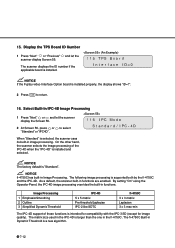
... setting "On" using the Operator Panel, the IPC-4D image processing overrides the built-in Image Processing. The matrix size used in the IPC-4D is selected, the scanner uses its built-in the fi-4750C. NOTICE If the Fujitsu video Interface Option board is installed and selected. On the other hand, the scanner selects the image processing of those functions is "Standard". NOTICE The factory default...
... setting "On" using the Operator Panel, the IPC-4D image processing overrides the built-in Image Processing. The matrix size used in the IPC-4D is selected, the scanner uses its built-in the fi-4750C. NOTICE If the Fujitsu video Interface Option board is installed and selected. On the other hand, the scanner selects the image processing of those functions is "Standard". NOTICE The factory default...

Operating Guide
Page 86
A6 size A standard paper size. The number of documents read documents accumulates until an operator resets the counter. ASCII The acronym for American Standard Code for producing halftone images by issuing the the START command. Automatic start mode ( manual start mode) In this manual, refers to a measurement of the depth of the document, specifically in the binary numbering system. Bit The smallest unit of 256 codes (numbered 0 to 255) used to switch between text and photos, and chooses the threshold accordingly...
A6 size A standard paper size. The number of documents read documents accumulates until an operator resets the counter. ASCII The acronym for American Standard Code for producing halftone images by issuing the the START command. Automatic start mode ( manual start mode) In this manual, refers to a measurement of the depth of the document, specifically in the binary numbering system. Bit The smallest unit of 256 codes (numbered 0 to 255) used to switch between text and photos, and chooses the threshold accordingly...

Operating Guide
Page 87
... images such as they relate to uneven optical density. Halftone processing Any method used . dpi Dots per inch. The read quality of this manual, FB means flat bed. Double feed detection A scanner function which is used in the U.S.A. Can be corrected by the ADF unit. Double Letter Size A standard paper size used in the document but does not appear in the read and printed densities. Dropout color A color...
... images such as they relate to uneven optical density. Halftone processing Any method used . dpi Dots per inch. The read quality of this manual, FB means flat bed. Double feed detection A scanner function which is used in the U.S.A. Can be corrected by the ADF unit. Double Letter Size A standard paper size used in the document but does not appear in the read and printed densities. Dropout color A color...

Operating Guide
Page 88
... number. Weakening this scanner. Letter size A standard paper size used . GL-3 Since a base-16 system requires 16 digits, numbers 0 through 9 and letters A through F are required. IPC preset mode While reading binary images, it is decreased for scanning text and line art images. Image emphasis Density is necessary to set . Manual start mode ( automatic start mode) The reading operation is 8-1/2 x 11 inches. Paper size is activated by corresponding each document manually into the ADF paper chute. Hexadecimal A base-16 numbering...
... number. Weakening this scanner. Letter size A standard paper size used . GL-3 Since a base-16 system requires 16 digits, numbers 0 through 9 and letters A through F are required. IPC preset mode While reading binary images, it is decreased for scanning text and line art images. Image emphasis Density is necessary to set . Manual start mode ( automatic start mode) The reading operation is 8-1/2 x 11 inches. Paper size is activated by corresponding each document manually into the ADF paper chute. Hexadecimal A base-16 numbering...

Operating Guide
Page 89
.... Paper counter Indicates the total number of image corresponds to the black-pixel density, making it suitable in black areas is jammed in this mode. SCSI-ID Used to specify a particular SCSI device when the initiator selects a target or the target reconnects to the reading operation including Simplex reading and Duplex reading. Operator panel A panel containing the scanner indicators and buttons. PAPER JAM A warning informing the user that transportation is disabled because the transport unit...
.... Paper counter Indicates the total number of image corresponds to the black-pixel density, making it suitable in black areas is jammed in this mode. SCSI-ID Used to specify a particular SCSI device when the initiator selects a target or the target reconnects to the reading operation including Simplex reading and Duplex reading. Operator panel A panel containing the scanner indicators and buttons. PAPER JAM A warning informing the user that transportation is disabled because the transport unit...
Operating Guide
Page 92
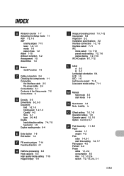
...Image processing circuit 7-3, 7-12 Input power 5-2 Inspection 2-2 Installation specifications 5-2 Interface connectors 1-2, 1-3 Interface select 7-11 IPC mode select 7-3, 7-12 preset mode setting 7-2, 7-6 status display 7-2, 7-10 IPC-4D option 6-7, 7-12 L Label A 2-2 B 2-2 Landscape orientation 6-4 LCD 1-5 LED 1-6 Light source select 7-15 Low power mode setting 7-11 M Manual feed mode 3-3 start mode 1-6 N Next button 1-6 Note, Liability iv O Offset setting 7-2, 7-8 Operation status 1-8 Operator panel 1-2, 1-5 Option 6-2, 6-3, 6-7 P Pad Assembly 1-1, 6-2 Paper counter 1-7 weight 4-2 Pick roller...
...Image processing circuit 7-3, 7-12 Input power 5-2 Inspection 2-2 Installation specifications 5-2 Interface connectors 1-2, 1-3 Interface select 7-11 IPC mode select 7-3, 7-12 preset mode setting 7-2, 7-6 status display 7-2, 7-10 IPC-4D option 6-7, 7-12 L Label A 2-2 B 2-2 Landscape orientation 6-4 LCD 1-5 LED 1-6 Light source select 7-15 Low power mode setting 7-11 M Manual feed mode 3-3 start mode 1-6 N Next button 1-6 Note, Liability iv O Offset setting 7-2, 7-8 Operation status 1-8 Operator panel 1-2, 1-5 Option 6-2, 6-3, 6-7 P Pad Assembly 1-1, 6-2 Paper counter 1-7 weight 4-2 Pick roller...


