
Cleaning & Maintenance
Page 15
CONTENTS ❏ CHAPTER 1 ❏ CHAPTER 2 ❏ CHAPTER 3 ❏ CHAPTER 4 DESCRIPTION 1-1 Units 1-2 Assemblies 1-4 Operator panel 1-5 Panel Display 1-7 CLEANING 2-1 Cleaning Supplies and Areas Requiring Cleaning 2-2 Supplies 2-2 Areas Requiring Cleaning 2-3 Cleaning the ADF 2-4 Cleaning the Document bed 2-9 REPLACEMENT OF CONSUMABLES ..... 3-1 Consumable Lists 3-2 Pad ASSY 3-3 Pick Roller 3-5 TROUBLESHOOTING 4-1 Clearing Paper Jams 4-2 Initial Checks 4-3 NOTES 4-13 Problem Checklist 4-20 xiii
CONTENTS ❏ CHAPTER 1 ❏ CHAPTER 2 ❏ CHAPTER 3 ❏ CHAPTER 4 DESCRIPTION 1-1 Units 1-2 Assemblies 1-4 Operator panel 1-5 Panel Display 1-7 CLEANING 2-1 Cleaning Supplies and Areas Requiring Cleaning 2-2 Supplies 2-2 Areas Requiring Cleaning 2-3 Cleaning the ADF 2-4 Cleaning the Document bed 2-9 REPLACEMENT OF CONSUMABLES ..... 3-1 Consumable Lists 3-2 Pad ASSY 3-3 Pick Roller 3-5 TROUBLESHOOTING 4-1 Clearing Paper Jams 4-2 Initial Checks 4-3 NOTES 4-13 Problem Checklist 4-20 xiii

Cleaning & Maintenance
Page 22
Assemblies Stacker Pick rollers Guide A ASSY Pad ASSY G 1-4
Assemblies Stacker Pick rollers Guide A ASSY Pad ASSY G 1-4

Operator's Guide
Page 23
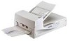
.... Units and Assemblies This section shows the exterior view and assemblies of each part and describes its functions. I Units (1)Document cover (4)Automatic document feeder(ADF) (3)Document holding pad (2)Document bed (5)Stacker (7)Transport Lever (6)Operator panel (9)ADF lever (8)ADF paper chute (17)Spare Pad ASSY (16)Third... party slot (Option board Slot) (10)Power switch (11)Power Inlet (12)EXT connector (15)Interface connector (14)SCSI ID switch (13)SCSI terminator switch NOTICE The transport lever should be switched to the operating position when the scanner...
.... Units and Assemblies This section shows the exterior view and assemblies of each part and describes its functions. I Units (1)Document cover (4)Automatic document feeder(ADF) (3)Document holding pad (2)Document bed (5)Stacker (7)Transport Lever (6)Operator panel (9)ADF lever (8)ADF paper chute (17)Spare Pad ASSY (16)Third... party slot (Option board Slot) (10)Power switch (11)Power Inlet (12)EXT connector (15)Interface connector (14)SCSI ID switch (13)SCSI terminator switch NOTICE The transport lever should be switched to the operating position when the scanner...

Operator's Guide
Page 24
...Document holding pad Presses document to the Document bed. 4 Automatic document feeder Automatically feeds documents to be read documents. 6 Operator panel Contains indicator panel that indicates scanner status. 7 Transport Lever Transport lever Secures the carrier unit. No . Set to locked position when moving scanner. 8 ADF paper chute Holds the documents...with interface cables. 16 Third party slot A Fujitsu VIDEO INTERFACE BOARD or fi-CMP3(JPEG COMPRESSION BOARD) is installed. 17 Spare Pad ASSY Spare pad assembly. (One spare pad assembly is the final device on the SCSI daisy...
...Document holding pad Presses document to the Document bed. 4 Automatic document feeder Automatically feeds documents to be read documents. 6 Operator panel Contains indicator panel that indicates scanner status. 7 Transport Lever Transport lever Secures the carrier unit. No . Set to locked position when moving scanner. 8 ADF paper chute Holds the documents...with interface cables. 16 Third party slot A Fujitsu VIDEO INTERFACE BOARD or fi-CMP3(JPEG COMPRESSION BOARD) is installed. 17 Spare Pad ASSY Spare pad assembly. (One spare pad assembly is the final device on the SCSI daisy...
Operator's Guide
Page 109
... 1-4 erasing edges 7-14 lever 1-4 mode 6-4 Alarm 6-5 Ambient condition 10-3 Arrangement 1-6 Assemblies 1-5 B Button/LED Function 1-7 C Cable Connections 2-4 Checking the components 1-2 Confirm of the Manufacturing Labels .. 2-2 Connecting the interface cable 2-4 Consumables 9-2 Contents of the Setup Mode 7-3 Conventions 1-viii D Density 9-6 Dimensions 10-3, 10-4 Document bed 1-4 holding pad 1-4 Quality 5-3 Size 5-2 type 4-6, 5-3 Double feed detection setting 7-5, 7-6 feed error...
... 1-4 erasing edges 7-14 lever 1-4 mode 6-4 Alarm 6-5 Ambient condition 10-3 Arrangement 1-6 Assemblies 1-5 B Button/LED Function 1-7 C Cable Connections 2-4 Checking the components 1-2 Confirm of the Manufacturing Labels .. 2-2 Connecting the interface cable 2-4 Consumables 9-2 Contents of the Setup Mode 7-3 Conventions 1-viii D Density 9-6 Dimensions 10-3, 10-4 Document bed 1-4 holding pad 1-4 Quality 5-3 Size 5-2 type 4-6, 5-3 Double feed detection setting 7-5, 7-6 feed error...

Operator's Guide
Page 110
N Next button 1-7 O Offset setting 7-3, 7-9 Operation status 6-3 Operator panel 1-6 Option 9-3, 9-4 P Pad Assembly 9-2 Paper counter 6-2 weight 5-3 Pick roller 9-2 start time setting 7-3, 7-8 Plain paper 5-3 Portrait 9-6 Power consumption 10-3 inlet 1-4 switch 1-4 Precautions 5-3 Preface 1-vii Previous button 1-7 R Read Color 7-17 Reading ...1-4 Time-out limit setting 7-9 TPS board ID number display .......... 7-13 Transport Lever 2-3 Turning the power off 2-3 the power on 4-2 U Unicolor Reading 7-17 Units 1-3 Units and Assemblies 1-3 W Weight 10-3 Z (Enter)button 1-7
N Next button 1-7 O Offset setting 7-3, 7-9 Operation status 6-3 Operator panel 1-6 Option 9-3, 9-4 P Pad Assembly 9-2 Paper counter 6-2 weight 5-3 Pick roller 9-2 start time setting 7-3, 7-8 Plain paper 5-3 Portrait 9-6 Power consumption 10-3 inlet 1-4 switch 1-4 Precautions 5-3 Preface 1-vii Previous button 1-7 R Read Color 7-17 Reading ...1-4 Time-out limit setting 7-9 TPS board ID number display .......... 7-13 Transport Lever 2-3 Turning the power off 2-3 the power on 4-2 U Unicolor Reading 7-17 Units 1-3 Units and Assemblies 1-3 W Weight 10-3 Z (Enter)button 1-7

