
English Manual.
Page 1
Q57M Series Motherboard User's Manual
Q57M Series Motherboard User's Manual

English Manual.
Page 2
... to inform the user of this symbol indicates that can help prevent potential negative consequences for Q57M Series motherboard. Symbol description: ! Although the information in this manual may not be changed or modified at any time, Foxconn does not obligate itself to avoid problems. WARNING! All images are registered trademarks of this product...
... to inform the user of this symbol indicates that can help prevent potential negative consequences for Q57M Series motherboard. Symbol description: ! Although the information in this manual may not be changed or modified at any time, Foxconn does not obligate itself to avoid problems. WARNING! All images are registered trademarks of this product...

English Manual.
Page 3
... information technology equipment ■ EN 61000-3-2/:2000 Electromagnetic compatibility (EMC) Part 3: Limits Section 2: Limits for harmonic current emissions (equipment input current declares that the product Motherboard Q57M is in conformity with (reference to the specification under which conformity is declared in accordance with 89/336 EEC-EMC Directive) ■ EN 55022: 1998...
... information technology equipment ■ EN 61000-3-2/:2000 Electromagnetic compatibility (EMC) Part 3: Limits Section 2: Limits for harmonic current emissions (equipment input current declares that the product Motherboard Q57M is in conformity with (reference to the specification under which conformity is declared in accordance with 89/336 EEC-EMC Directive) ■ EN 55022: 1998...
English Manual.
Page 4
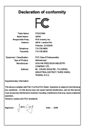
...-738-8868 714-738-8838 Equipment Classification: Type of conformity Trade Name: Model Name: Responsible Party: Address: Telephone: Facsimile: FOXCONN Q57M PCE Industry Inc. 458 E. Declaration of Product: Manufacturer: Address: FCC Class B Subassembly Motherboard HON HAI PRECISION INDUSTRY COMPANY LTD 66 , CHUNG SHAN RD., TU-CHENG INDUSTRIAL DISTRICT, TAIPEI HSIEN, TAIWAN, R.O.C. Lambert Rd...
...-738-8868 714-738-8838 Equipment Classification: Type of conformity Trade Name: Model Name: Responsible Party: Address: Telephone: Facsimile: FOXCONN Q57M PCE Industry Inc. 458 E. Declaration of Product: Manufacturer: Address: FCC Class B Subassembly Motherboard HON HAI PRECISION INDUSTRY COMPANY LTD 66 , CHUNG SHAN RD., TU-CHENG INDUSTRIAL DISTRICT, TAIPEI HSIEN, TAIWAN, R.O.C. Lambert Rd...
English Manual.
Page 5
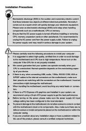
... supply is turned off before installing or removing CPU, memory, expansion cards or other peripherals. Normally it comes out as a motherboard, CPU or memory. ■ Ensure that flows between two objects at different electrical potentials. CAUTION ! Please carefully read the... following procedures to the use of your system. Normal operation depends on the motherboard. Please wear an electrostatic discharge (ESD) wrist strap when handling components such as a spark which will quickly damage your computer ...
... supply is turned off before installing or removing CPU, memory, expansion cards or other peripherals. Normally it comes out as a motherboard, CPU or memory. ■ Ensure that flows between two objects at different electrical potentials. CAUTION ! Please carefully read the... following procedures to the use of your system. Normal operation depends on the motherboard. Please wear an electrostatic discharge (ESD) wrist strap when handling components such as a spark which will quickly damage your computer ...

English Manual.
Page 8
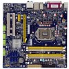
Thank you for today multi-media computing requirements, Q57M enables you need for break-through performance. With advanced overclocking capability and a range of connectivity features for buying Foxconn Q57M Series motherboard. This chapter includes the following information: ■ Product Specifications ■ Layout ■ Back Panel Connectors Foxconn products are engineered to maximize computing power, providing only what you to unleash more power from your computer.
Thank you for today multi-media computing requirements, Q57M enables you need for break-through performance. With advanced overclocking capability and a range of connectivity features for buying Foxconn Q57M Series motherboard. This chapter includes the following information: ■ Product Specifications ■ Layout ■ Back Panel Connectors Foxconn products are engineered to maximize computing power, providing only what you to unleash more power from your computer.
English Manual.
Page 11
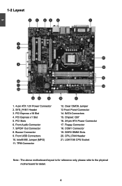
... 21. 1-2 Layout 6 5 43 2 1 1 7 8 21 9 20 10 11 12 13 14 15 1. 4-pin ATX 12V Power Connector 2. SATA Connectors 15. LGA1156 CPU Socket Note : The above motherboard layout is for reference only, please refer to the physical...
... 21. 1-2 Layout 6 5 43 2 1 1 7 8 21 9 20 10 11 12 13 14 15 1. 4-pin ATX 12V Power Connector 2. SATA Connectors 15. LGA1156 CPU Socket Note : The above motherboard layout is for reference only, please refer to the physical...
English Manual.
Page 14
... the Memory ■ Install an Expansion Card ■ Install other Internal Connectors ■ Jumpers Please visit the following website for more supporting information about your motherboard. Please refer to the motherboard layout prior to any installation and read the contents in this chapter carefully.
... the Memory ■ Install an Expansion Card ■ Install other Internal Connectors ■ Jumpers Please visit the following website for more supporting information about your motherboard. Please refer to the motherboard layout prior to any installation and read the contents in this chapter carefully.
English Manual.
Page 15
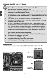
...specifications. The CPU cannot be set the frequency beyond hardware specifications since it enabled Install the CPU Locate the alignment keys on the motherboard CPU socket and the notches on the computer if the CPU cooler is optimized for HT Technology ■ A BIOS that the ...incorrectly. (Or you wish to set beyond the standard specifications, please do so according to install the CPU : ■ Make sure that the motherboard supports the CPU. ■ Always turn on the CPU. Hyper-Threading Technology System Requirements: (Go to prevent hardware damage. ■ Locate ...
...specifications. The CPU cannot be set the frequency beyond hardware specifications since it enabled Install the CPU Locate the alignment keys on the motherboard CPU socket and the notches on the computer if the CPU cooler is optimized for HT Technology ■ A BIOS that the ...incorrectly. (Or you wish to set beyond the standard specifications, please do so according to install the CPU : ■ Make sure that the motherboard supports the CPU. ■ Always turn on the CPU. Hyper-Threading Technology System Requirements: (Go to prevent hardware damage. ■ Locate ...
English Manual.
Page 17
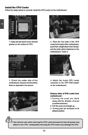
Check the solder side of CPU. 2. Place the four bolts of the CPU cooler to the holes of the motherboard, push them straight down from motherboard : 1.Turning the push pin (bolt) along with the direction of CPU cooler from the top, and the bolts will be fixed as .... 4. That's it. 3. Install the CPU Cooler Follow the steps below to correctly install the CPU cooler on the surface of the motherboard, the push pin should be fastened on the motherboard . 3 2 1 Release bolts of arrow (counterclockwise). 2. Attach the 4-wire CPU cooler connector to the CPU FAN header on the...
Check the solder side of CPU. 2. Place the four bolts of the CPU cooler to the holes of the motherboard, push them straight down from motherboard : 1.Turning the push pin (bolt) along with the direction of CPU cooler from the top, and the bolts will be fixed as .... 4. That's it. 3. Install the CPU Cooler Follow the steps below to correctly install the CPU cooler on the surface of the motherboard, the push pin should be fastened on the motherboard . 3 2 1 Release bolts of arrow (counterclockwise). 2. Attach the 4-wire CPU cooler connector to the CPU FAN header on the...
English Manual.
Page 18
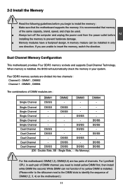
... : Channel 0 : DIMM1 , DIMM2 Channel 1 : DIMM3 , DIMM4 The combinations of DIMM modules are two pairs of DIMM(1,2, 3, 4) on the motherboard.) 11 11 CAUTION DS/SS Single Channel - - - DS/SS DS/SS Dual Channel - Dual Channel DS/SS DS/SS DS/SS (DS :... (Please refer to the silkscreen next to the DIMM slots to insert the memory, switch the direction. 2 Dual Channel Memory Configuration This motherboard provides Four DDR3 memory sockets and supports Dual Channel Technology. Single Channel - - Dual Channel - DIMM3 - Single Channel DS/SS DS/...
... : Channel 0 : DIMM1 , DIMM2 Channel 1 : DIMM3 , DIMM4 The combinations of DIMM modules are two pairs of DIMM(1,2, 3, 4) on the motherboard.) 11 11 CAUTION DS/SS Single Channel - - - DS/SS DS/SS Dual Channel - Dual Channel DS/SS DS/SS DS/SS (DS :... (Please refer to the silkscreen next to the DIMM slots to insert the memory, switch the direction. 2 Dual Channel Memory Configuration This motherboard provides Four DDR3 memory sockets and supports Dual Channel Technology. Single Channel - - Dual Channel - DIMM3 - Single Channel DS/SS DS/...
English Manual.
Page 19
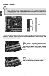
..., make sure to turn off the computer and unplug the power cord from the power outlet to prevent damage to install DDR3 DIMMs on this motherboard. Notch If you take a look at front side of the memory socket.
..., make sure to turn off the computer and unplug the power cord from the power outlet to prevent damage to install DDR3 DIMMs on this motherboard. Notch If you take a look at front side of the memory socket.
English Manual.
Page 20
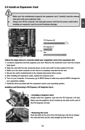
CAUTION 2 2-3 Install an Expansion Card ! ■ Make sure the motherboard supports the expansion card. Locate an expansion slot that came with the expansion card in the slot. 3. Make sure the metal contacts on the card ...
CAUTION 2 2-3 Install an Expansion Card ! ■ Make sure the motherboard supports the expansion card. Locate an expansion slot that came with the expansion card in the slot. 3. Make sure the metal contacts on the card ...

English Manual.
Page 21
... +5V 12 3.3V 24 GND 12 PWR1 1 Pin No. 24 ! We recommend you are properly aligned with the connector on the motherboard. 2 CAUTION 2-4 Install other Internal Connectors Power Connectors This motherboard uses an ATX power supply. Firmly plug the power supply cable into the connector and make sure all the devices have...
... +5V 12 3.3V 24 GND 12 PWR1 1 Pin No. 24 ! We recommend you are properly aligned with the connector on the motherboard. 2 CAUTION 2-4 Install other Internal Connectors Power Connectors This motherboard uses an ATX power supply. Firmly plug the power supply cable into the connector and make sure all the devices have...
English Manual.
Page 22
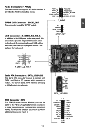
... to run applications more trustworthy. USB Connectors : F_USB1_A/2_A/3_A In addition to connect with them, user can quickly expand another USB ports on its motherboard. PORT1_L PORT1_R PORT2_R SENSE_SEND PORT2_L 12 AUD_GND PRESENCEJ SENSE1_RETURN EMPTY SENSE2_RETURN 9 10 F_AUDIO +5V 1 EMPTY 2 SPDIF_OUT 3 GND 4 SPDIF_OUT 12 VCC VCC D- It provides the Front...
... to run applications more trustworthy. USB Connectors : F_USB1_A/2_A/3_A In addition to connect with them, user can quickly expand another USB ports on its motherboard. PORT1_L PORT1_R PORT2_R SENSE_SEND PORT2_L 12 AUD_GND PRESENCEJ SENSE1_RETURN EMPTY SENSE2_RETURN 9 10 F_AUDIO +5V 1 EMPTY 2 SPDIF_OUT 3 GND 4 SPDIF_OUT 12 VCC VCC D- It provides the Front...

English Manual.
Page 23
...Power LED indicates the system's status. Power Switch Connector (PWR-SW) Connect to the chassis front panel IDE indicator LED. Push this motherboard. It indicates the active status of the chassis. This 2-pin connector is pressed. the system will restart when the switch is directional ...with +/- When the system is in "PC Health Status" section of the BIOS Setup. COM Connector : COM1 This motherboard supports one end to connect with a 9-pin D-sub connector at one serial RS232 COM port for connecting the front panel switch and LED Indicators...
...Power LED indicates the system's status. Power Switch Connector (PWR-SW) Connect to the chassis front panel IDE indicator LED. Push this motherboard. It indicates the active status of the chassis. This 2-pin connector is pressed. the system will restart when the switch is directional ...with +/- When the system is in "PC Health Status" section of the BIOS Setup. COM Connector : COM1 This motherboard supports one end to connect with a 9-pin D-sub connector at one serial RS232 COM port for connecting the front panel switch and LED Indicators...
English Manual.
Page 24
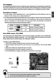
... turn it onto pins 1-2 to store the basic hardware information (such as "1". 2. The following content carefully prior to modifying any jumper on this motherboard to use the various functions of this manual, pin 1 is simply labeled as BIOS data, date, time information, hardware password... Jumper 1 Diagram... by the bold silkscreen next to temporarily short them . 2 2-5 Jumpers For some features needed, users can change the jumper settings on this motherboard, pin 1 can be done by touching two pins by a screwdriver for a few seconds, but using jumper cap is recommended. Plug in next...
... turn it onto pins 1-2 to store the basic hardware information (such as "1". 2. The following content carefully prior to modifying any jumper on this motherboard to use the various functions of this manual, pin 1 is simply labeled as BIOS data, date, time information, hardware password... Jumper 1 Diagram... by the bold silkscreen next to temporarily short them . 2 2-5 Jumpers For some features needed, users can change the jumper settings on this motherboard, pin 1 can be done by touching two pins by a screwdriver for a few seconds, but using jumper cap is recommended. Plug in next...

English Manual.
Page 25
... Intel® Management Engine function. Intel® Management Engine (ME) is an embedded microcontroller located in Intel chipset. 2 CAUTION Intel® ME Jumper: MFG This motherboard uses MFG jumper to improve management of corporate assets. Set the jumper to pins 2-3 first. 18 18 Before flashing BIOS ROM, you need to set...
... Intel® Management Engine function. Intel® Management Engine (ME) is an embedded microcontroller located in Intel chipset. 2 CAUTION Intel® ME Jumper: MFG This motherboard uses MFG jumper to improve management of corporate assets. Set the jumper to pins 2-3 first. 18 18 Before flashing BIOS ROM, you need to set...
English Manual.
Page 31
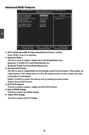
... This item is normal, S5 wake up only by pressing the power button. Enable: S1/S3/S4 is used to reduce the power consumption of motherboard. When enable, the suspend power of the chipset will be cut off in S5 suspend mode in order to enable/disable the EuP(Energy-using...
... This item is normal, S5 wake up only by pressing the power button. Enable: S1/S3/S4 is used to reduce the power consumption of motherboard. When enable, the suspend power of the chipset will be cut off in S5 suspend mode in order to enable/disable the EuP(Energy-using...
English Manual.
Page 33
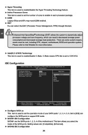
Copyright (C) 1985-2009, American Megatrends, Inc. This item allows you select the mode of the motherboard. Setting values are some system requirements must be met, including CPU, chipset, motherboard, BIOS and operation system. There are : [Compatible], [Enhanced]. ► SATA#2 IDE Configuration 26 IDE Configuration CMOS Setup Utility - 3 CAUTION ► Hyper Threading This item...
Copyright (C) 1985-2009, American Megatrends, Inc. This item allows you select the mode of the motherboard. Setting values are some system requirements must be met, including CPU, chipset, motherboard, BIOS and operation system. There are : [Compatible], [Enhanced]. ► SATA#2 IDE Configuration 26 IDE Configuration CMOS Setup Utility - 3 CAUTION ► Hyper Threading This item...


