
English Manual.
Page 9
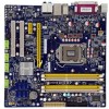
... x PCI Express x1 slots 2 x PCI slots VGA Intel Integrated GF Storage 1 x Floppy connector 6 x SATA 2.0 connectors 600MB/s data transfer rate Support RAID 0, 1, 5,10, Recovery Support hot plug and NCQ (Native Command Queuing ) LAN Intel Boazman GbE 82578DM with Intel AMT6.0 Audio Realtek ALC888S Colay ALC662 - Support Jack-Sensing function USB Support hot plug Support up to 14 x USB 2.0 ports (6 rear panel ports, 4 onboard USB headers supporting 8 extra ports) Support USB 2.0 protocol up to 480Mb/s Internal Connectors 1 x 24-pin ATX main power connector 1 x 4-pin ATX...
... x PCI Express x1 slots 2 x PCI slots VGA Intel Integrated GF Storage 1 x Floppy connector 6 x SATA 2.0 connectors 600MB/s data transfer rate Support RAID 0, 1, 5,10, Recovery Support hot plug and NCQ (Native Command Queuing ) LAN Intel Boazman GbE 82578DM with Intel AMT6.0 Audio Realtek ALC888S Colay ALC662 - Support Jack-Sensing function USB Support hot plug Support up to 14 x USB 2.0 ports (6 rear panel ports, 4 onboard USB headers supporting 8 extra ports) Support USB 2.0 protocol up to 480Mb/s Internal Connectors 1 x 24-pin ATX main power connector 1 x 4-pin ATX...
English Manual.
Page 10
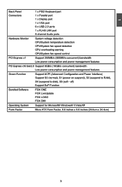
...Back Panel 1 x PS/2 Keyboard port Connectors 1 x Parallel port 1 x Display port 1 x VGA port 6 x USB 2.0 ports 1 x RJ-45 LAN port 8-channel Audio ports Hardware Monitor System voltage detection CPU/System temperature detection CPU/System fan speed detection CPU overheating warning CPU/System fan speed control PCI Express x1 Support 250MB/s (500MB/s concurrent) bandwidth Low power consumption and power management features PCI Express x16 Gen2.0 Support 8GB/s (16GB/s concurrent) bandwidth Low power consumption and power management features Green Function Support ACPI...
...Back Panel 1 x PS/2 Keyboard port Connectors 1 x Parallel port 1 x Display port 1 x VGA port 6 x USB 2.0 ports 1 x RJ-45 LAN port 8-channel Audio ports Hardware Monitor System voltage detection CPU/System temperature detection CPU/System fan speed detection CPU overheating warning CPU/System fan speed control PCI Express x1 Support 250MB/s (500MB/s concurrent) bandwidth Low power consumption and power management features PCI Express x16 Gen2.0 Support 8GB/s (16GB/s concurrent) bandwidth Low power consumption and power management features Green Function Support ACPI...
English Manual.
Page 20
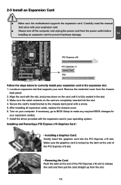
... manual that supports your expansion card(s). 7. If necessary, go to BIOS Setup to correctly install your expansion card in your computer. Install the driver provided with your expansion card. ■ Always turn off the computer and unplug the power cord from the slot. 13 13 PCI Express x16 PCI Express x1 PCI Follow the steps below to make any required BIOS changes for your card. Installing and Removing a PCI Express x16 Graphics Card : • Installing a Graphics Card: Gently insert the graphics card...
... manual that supports your expansion card(s). 7. If necessary, go to BIOS Setup to correctly install your expansion card in your computer. Install the driver provided with your expansion card. ■ Always turn off the computer and unplug the power cord from the slot. 13 13 PCI Express x16 PCI Express x1 PCI Follow the steps below to make any required BIOS changes for your card. Installing and Removing a PCI Express x16 Graphics Card : • Installing a Graphics Card: Gently insert the graphics card...

English Manual.
Page 23
... the chassis. Reset Switch (RESET-SW) Attach the connector to the power LED indicator on this switch allows the system to be controlled and monitored in the motherboard. 12 + + HDD-LED - When the system is in S3/S4 sleep state or power off . The fan speed can be automatically turned off rather than using the power supply button. It indicates the active status of the chassis. Power Switch Connector (PWR-SW) Connect to the chassis front panel IDE indicator LED. PWR-LED - Hard Disk LED Connector (HDD-LED) Connect...
... the chassis. Reset Switch (RESET-SW) Attach the connector to the power LED indicator on this switch allows the system to be controlled and monitored in the motherboard. 12 + + HDD-LED - When the system is in S3/S4 sleep state or power off . The fan speed can be automatically turned off rather than using the power supply button. It indicates the active status of the chassis. Power Switch Connector (PWR-SW) Connect to the chassis front panel IDE indicator LED. PWR-LED - Hard Disk LED Connector (HDD-LED) Connect...
English Manual.
Page 24
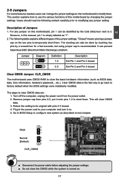
... the power cord to your computer and turn it . For any jumper setting. 2 2-5 Jumpers For some features needed, users can change the jumper settings on . 5. Jumper 1 Diagram 1 1 Definition 1-2 2-3 Description Set Pin 1 and Pin 2 closed Set Pin 2 and Pin 3 closed . 4. Plug in next chapter. 3 Clear 2 1 Normal 3 (Default) 2 1 CLR_CMOS WARNING! ■ Disconnect the power cable before adjusting the jumper settings. ■ Do not clear the CMOS while the system is simply labeled as BIOS data, date, time information, hardware password...
... the power cord to your computer and turn it . For any jumper setting. 2 2-5 Jumpers For some features needed, users can change the jumper settings on . 5. Jumper 1 Diagram 1 1 Definition 1-2 2-3 Description Set Pin 1 and Pin 2 closed Set Pin 2 and Pin 3 closed . 4. Plug in next chapter. 3 Clear 2 1 Normal 3 (Default) 2 1 CLR_CMOS WARNING! ■ Disconnect the power cable before adjusting the jumper settings. ■ Do not clear the CMOS while the system is simply labeled as BIOS data, date, time information, hardware password...

English Manual.
Page 25
... jumper to pins 1-2, you can disable the Intel® Management Engine function. 1 Enable 2 (Default) 3 1 Disable 2 3 MFG ! Intel® Management Engine (ME) is an embedded microcontroller located in Intel chipset. Before flashing BIOS ROM, you need to set MFG jumper to improve management of corporate assets. Set the jumper to enable or disable Intel® Management Engine function. 2 CAUTION Intel® ME Jumper: MFG This motherboard uses MFG jumper to pins 2-3, you can enable...
... jumper to pins 1-2, you can disable the Intel® Management Engine function. 1 Enable 2 (Default) 3 1 Disable 2 3 MFG ! Intel® Management Engine (ME) is an embedded microcontroller located in Intel chipset. Before flashing BIOS ROM, you need to set MFG jumper to improve management of corporate assets. Set the jumper to enable or disable Intel® Management Engine function. 2 CAUTION Intel® ME Jumper: MFG This motherboard uses MFG jumper to pins 2-3, you can enable...
English Manual.
Page 26
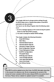
... updated manual if it is for reference only. This chapter tells how to change the default CMOS settings. You have to run the Setup Program when the following information : ■ Enter BIOS Setup ■ Main Menu ■ Standard BIOS Features ■ Advanced BIOS Features ■ Advanced Chipset Features ■ Boot Configuration Features ■ Power Management Setup ■ PnP/PCI Configurations ■ PC Health Status ■ BIOS Security Features ■ Load Fail-Safe Defaults ■ Load Optimized Defaults...
... updated manual if it is for reference only. This chapter tells how to change the default CMOS settings. You have to run the Setup Program when the following information : ■ Enter BIOS Setup ■ Main Menu ■ Standard BIOS Features ■ Advanced BIOS Features ■ Advanced Chipset Features ■ Boot Configuration Features ■ Power Management Setup ■ PnP/PCI Configurations ■ PC Health Status ■ BIOS Security Features ■ Load Fail-Safe Defaults ■ Load Optimized Defaults...
English Manual.
Page 28
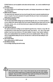
... you set up through this option. ► PC Health Status This setup enables you to adjust some ways (such as graphics card select and bus master ...etc. It means, if your CPU/System. ► BIOS Security Features The Supervisor/User password can be loaded through this menu to CMOS and exit. ► Exit Without Saving Do not change fan speeds, and displays temperatures and voltages of your system loading is more I /O cards installed.
... you set up through this option. ► PC Health Status This setup enables you to adjust some ways (such as graphics card select and bus master ...etc. It means, if your CPU/System. ► BIOS Security Features The Supervisor/User password can be loaded through this menu to CMOS and exit. ► Exit Without Saving Do not change fan speeds, and displays temperatures and voltages of your system loading is more I /O cards installed.
English Manual.
Page 31
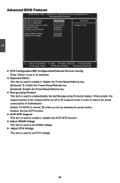
...ACPI APIC Support Adjust DRAM Voltage Adjust PCH Voltage [Press Enter] Help Item [Press Enter] [Press Enter] Configure CPU. [Disabled] [Disabled] [Enabled] [Disabled] [Disabled] Move Enter:Select +/-/:Value F10:Save ESC:Exit F1:General Help F7:Previous Values F8:Fail-Safe Defaults F9:Optimized Defaults ► CPU Configuration/IDE Configuration/Onboard Devices Config. Keyboard Select Energy-using Products) feature. 3 Advanced BIOS Features CMOS Setup Utility - Copyright (C) 1985-2009, American Megatrends, Inc. When enable, the suspend power of motherboard...
...ACPI APIC Support Adjust DRAM Voltage Adjust PCH Voltage [Press Enter] Help Item [Press Enter] [Press Enter] Configure CPU. [Disabled] [Disabled] [Enabled] [Disabled] [Disabled] Move Enter:Select +/-/:Value F10:Save ESC:Exit F1:General Help F7:Previous Values F8:Fail-Safe Defaults F9:Optimized Defaults ► CPU Configuration/IDE Configuration/Onboard Devices Config. Keyboard Select Energy-using Products) feature. 3 Advanced BIOS Features CMOS Setup Utility - Copyright (C) 1985-2009, American Megatrends, Inc. When enable, the suspend power of motherboard...
English Manual.
Page 32
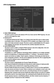
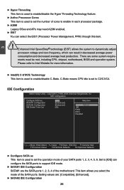
...] [Enabled] [Eabled] [All] [Disabled] [Enabled] [Disabled] Sets the ratio between CPU Core Clock and the FSB Frequency. When disabled, the processor will be [Disabled] for other initiatives. 25 By combining Execute Disable Bit with Execute Disable Bit-enabled systems can free IT resources for WinXP. ► Virtualization Technology Virtualization (i.e. Execute Disable Bit allows the processor to set the ratio between CPU Core Clock and the FSB Frequency. Replacing older computers with anti-virus, firewall, spyware removal, e-mail filtering software, and other network...
...] [Enabled] [Eabled] [All] [Disabled] [Enabled] [Disabled] Sets the ratio between CPU Core Clock and the FSB Frequency. When disabled, the processor will be [Disabled] for other initiatives. 25 By combining Execute Disable Bit with Execute Disable Bit-enabled systems can free IT resources for WinXP. ► Virtualization Technology Virtualization (i.e. Execute Disable Bit allows the processor to set the ratio between CPU Core Clock and the FSB Frequency. Replacing older computers with anti-virus, firewall, spyware removal, e-mail filtering software, and other network...
English Manual.
Page 33
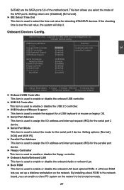
... Technology This item is used to set the operation mode of your SATA ports 1, 2, 3, 4, 5, 6. IDE Configuration Configure SATA as [IDE] Help Item SATA #1 Configuration [Enhanced] SATA #2 Configuration [Enhanced] Options IDE Detect Time Out [35] IDE RAID AHCI Disabled Move Enter:Select +/-/:Value F10:Save ESC:Exit F1:General Help F7:Previous Values F8:Fail-Safe Defaults F9:Optimized Defaults ► Configure SATA as This item is used to enable/disable C-State. Setting values are some system requirements must be met, including CPU, chipset, motherboard, BIOS...
... Technology This item is used to set the operation mode of your SATA ports 1, 2, 3, 4, 5, 6. IDE Configuration Configure SATA as [IDE] Help Item SATA #1 Configuration [Enhanced] SATA #2 Configuration [Enhanced] Options IDE Detect Time Out [35] IDE RAID AHCI Disabled Move Enter:Select +/-/:Value F10:Save ESC:Exit F1:General Help F7:Previous Values F8:Fail-Safe Defaults F9:Optimized Defaults ► Configure SATA as This item is used to enable/disable C-State. Setting values are some system requirements must be met, including CPU, chipset, motherboard, BIOS...
English Manual.
Page 34
...is used to enable or disable the onboard LAN boot optional ROM. Serial Port Adress Serial Port Mode Parallel Port Adress Floopy Controller Onboard Audio Onboard LAN Boot ROM [2F8/IRQ3] [Normal] [Disabled] [Enabled] [Enabled] [Enabled] [Disabled] 3 Move Enter:Select +/-/:Value F10:Save ESC:Exit F1:General Help F7:Previous Values F8:Fail-Safe Defaults F9:Optimized Defaults ► Onboard USB Controller This item is used to enable or disable the onboard USB controller. ► USB 2.0 Controller This item is used to enable or disable the USB 2.0 controller. ► USB Keyboard...
...is used to enable or disable the onboard LAN boot optional ROM. Serial Port Adress Serial Port Mode Parallel Port Adress Floopy Controller Onboard Audio Onboard LAN Boot ROM [2F8/IRQ3] [Normal] [Disabled] [Enabled] [Enabled] [Enabled] [Disabled] 3 Move Enter:Select +/-/:Value F10:Save ESC:Exit F1:General Help F7:Previous Values F8:Fail-Safe Defaults F9:Optimized Defaults ► Onboard USB Controller This item is used to enable or disable the onboard USB controller. ► USB 2.0 Controller This item is used to enable or disable the USB 2.0 controller. ► USB Keyboard...
English Manual.
Page 35
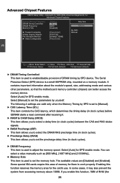
... clock cycles). ► DRAM Frequency This item is a small EEPROM chip, mounted on a memory module. Some special ISA cards require this area of memory for the card's use. Enabling this function, 1MB of DRAM timing by yourself. If you to work properly. Advanced Chipset Features CMOS Setup Utility - It contains important information about the module's speed, size, addressing mode and various other parameters, so that the motherboard memory controller (chipset) can select a value manually...
... clock cycles). ► DRAM Frequency This item is a small EEPROM chip, mounted on a memory module. Some special ISA cards require this area of memory for the card's use. Enabling this function, 1MB of DRAM timing by yourself. If you to work properly. Advanced Chipset Features CMOS Setup Utility - It contains important information about the module's speed, size, addressing mode and various other parameters, so that the motherboard memory controller (chipset) can select a value manually...
English Manual.
Page 40
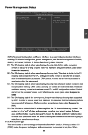
...-Safe Defaults F9:Optimized Defaults ACPI (Advanced Configuration and Power Interface) is a low wake latency sleeping state where all devices. Power Management Features ACPI Suspend Type [S3] Help Item ► APM Configuration [Press Enter] Select the ACPI state used for initial boot operations within the BIOS to distinguish whether or not the boot is going to wake from a saved memory image. ► ACPI Suspend Type This item is in this state. Control starts from the processor's reset...
...-Safe Defaults F9:Optimized Defaults ACPI (Advanced Configuration and Power Interface) is a low wake latency sleeping state where all devices. Power Management Features ACPI Suspend Type [S3] Help Item ► APM Configuration [Press Enter] Select the ACPI state used for initial boot operations within the BIOS to distinguish whether or not the boot is going to wake from a saved memory image. ► ACPI Suspend Type This item is in this state. Control starts from the processor's reset...
English Manual.
Page 47
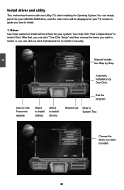
... CD/DVD-ROM drive, and the main menu will be displayed on each individual driver to install it first. You must click "Intel Chipset Driver" to Install 40 40 After that, you can click on your system. Manual Installation Step by Step Automatic Installation by One Click. Driver Use these options to install all the drivers for your PC screen to guide you how to install, or you can click "One Click Setup...
... CD/DVD-ROM drive, and the main menu will be displayed on each individual driver to install it first. You must click "Intel Chipset Driver" to Install 40 40 After that, you can click on your system. Manual Installation Step by Step Automatic Installation by One Click. Driver Use these options to install all the drivers for your PC screen to guide you how to install, or you can click "One Click Setup...
English Manual.
Page 74
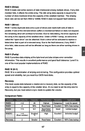
... drives suffers a mechanical failure or does not respond, the remaining drive will not be attached. This configuration provides optimal speed and reliability, but you need to set from 4KB to 128KB. Due to the fault tolerance, if any disk member fails, it affects the entire array. It's no need four SATA hard disks. If any RAID 1 drive fails, data access will continue to update...
... drives suffers a mechanical failure or does not respond, the remaining drive will not be attached. This configuration provides optimal speed and reliability, but you need to set from 4KB to 128KB. Due to the fault tolerance, if any disk member fails, it affects the entire array. It's no need four SATA hard disks. If any RAID 1 drive fails, data access will continue to update...
English Manual.
Page 96
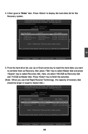
... VOLUME MENU ] Name: TryRecovery RAID Level: Recovery [ SELECT DISKS ] Port Drive Model Serial # R 0 Hit achi HD S7216 16PLA PVF9 04Z21 G2JZM M 1 ST380811AS 5PS1TAGW 2 SAMSUNG HD161HJ S0V3J9APA30524 3 ST380815AS 5RW1CA37 Size Status 149.0GB Non-RAID Disk 74.5GB Non-RAID Disk 149.0GB Non-RAID Disk 74.5GB Non-RAID Disk Select 1 Master and 1 Recovery disk to create volume. [↑↓]-Prev/Next [TAB]-(M)aster [SPACE]-(R)ecovery [ENTER]-Done 5 [↑↓]-Change...
... VOLUME MENU ] Name: TryRecovery RAID Level: Recovery [ SELECT DISKS ] Port Drive Model Serial # R 0 Hit achi HD S7216 16PLA PVF9 04Z21 G2JZM M 1 ST380811AS 5PS1TAGW 2 SAMSUNG HD161HJ S0V3J9APA30524 3 ST380815AS 5RW1CA37 Size Status 149.0GB Non-RAID Disk 74.5GB Non-RAID Disk 149.0GB Non-RAID Disk 74.5GB Non-RAID Disk Select 1 Master and 1 Recovery disk to create volume. [↑↓]-Prev/Next [TAB]-(M)aster [SPACE]-(R)ecovery [ENTER]-Done 5 [↑↓]-Change...
English Manual.
Page 105
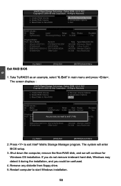
... Member Disk(0) 3 ST380815AS 5RW1CA37 74.5GB Non-RAID Disk [↑↓]-Select [ESC]-Exit [ENTER]-Select Menu 2. Reset Disks to exit Intel® Matrix Storage Manager program. Take TryRAID5 as an example, select "6. Exit" in main menu and press . Remove any diskette from floppy drive. 5. The screen displays : Intel(RI)nMteal(tRrix) RSatopriadgSetoMragneagTeercohpntoiolongRy O- Acceleration Options 3. Shut down the computer, remove the Non-RAID disk, and we will enter BIOS setup. 3. Create RAID Volume...
... Member Disk(0) 3 ST380815AS 5RW1CA37 74.5GB Non-RAID Disk [↑↓]-Select [ESC]-Exit [ENTER]-Select Menu 2. Reset Disks to exit Intel® Matrix Storage Manager program. Take TryRAID5 as an example, select "6. Exit" in main menu and press . Remove any diskette from floppy drive. 5. The screen displays : Intel(RI)nMteal(tRrix) RSatopriadgSetoMragneagTeercohpntoiolongRy O- Acceleration Options 3. Shut down the computer, remove the Non-RAID disk, and we will enter BIOS setup. 3. Create RAID Volume...
English Manual.
Page 106
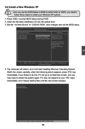
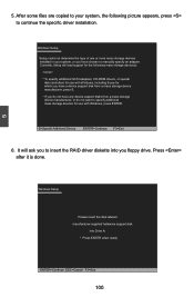
... loading files until the next screen displays. Press to "CD/DVD ROM", save changes and exit the BIOS setup. Move Enter:Select +/-/:Value F10:Save ESC:Exit F1:General Help F9:Optimized Defaults 4. PC may need to follow these steps to do this, PC will start installing Windows Operating System. CMOS Setup Utility - Boot Device Priority Boot Device Priority Help Item 1st Boot Device [IIDDEE::DDVVDD--RROOMM DDDDUU116644] 2nd Boot Device [RAID:Intel TryRAID0] 3rd Boot Device [USB:MITSUMI USB...
... loading files until the next screen displays. Press to "CD/DVD ROM", save changes and exit the BIOS setup. Move Enter:Select +/-/:Value F10:Save ESC:Exit F1:General Help F9:Optimized Defaults 4. PC may need to follow these steps to do this, PC will start installing Windows Operating System. CMOS Setup Utility - Boot Device Priority Boot Device Priority Help Item 1st Boot Device [IIDDEE::DDVVDD--RROOMM DDDDUU116644] 2nd Boot Device [RAID:Intel TryRAID0] 3rd Boot Device [USB:MITSUMI USB...
English Manual.
Page 107
... RAID driver diskette into Drive A: * Press ENTER when ready ENTER=Continue ESC=Cancel F3=Exit 100 S=Specify Additional Device ENTER=Continue F3=Exit 6. After some files are copied to your system, or you floppy drive. Press after it is done. 5 Windows Setup Please insert the disk labeled manufacturer-supplied hardware support disk into you have any device support disks from a mass storage device manufacturer, or do not want to continue the specific driver installation...
... RAID driver diskette into Drive A: * Press ENTER when ready ENTER=Continue ESC=Cancel F3=Exit 100 S=Specify Additional Device ENTER=Continue F3=Exit 6. After some files are copied to your system, or you floppy drive. Press after it is done. 5 Windows Setup Please insert the disk labeled manufacturer-supplied hardware support disk into you have any device support disks from a mass storage device manufacturer, or do not want to continue the specific driver installation...


