English Manual.
Page 6
... the Memory 11 Install an Expansion Card 13 Install other Internal Connectors 14 Jumpers 18 Chapter 3 BIOS Setup Enter BIOS Setup 22 Main Menu 22 Standard CMOS Features 24 Fox Central Control Unit 26 Advanced BIOS Features 29 Advanced Chipset Features 32 Integrated Peripherals 34 Security Chip Configuration 39 Power Management Setup 40...
... the Memory 11 Install an Expansion Card 13 Install other Internal Connectors 14 Jumpers 18 Chapter 3 BIOS Setup Enter BIOS Setup 22 Main Menu 22 Standard CMOS Features 24 Fox Central Control Unit 26 Advanced BIOS Features 29 Advanced Chipset Features 32 Integrated Peripherals 34 Security Chip Configuration 39 Power Management Setup 40...
English Manual.
Page 15
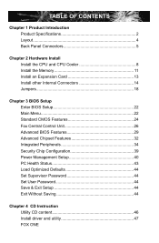
It is not recommended that supports HT Technology and has it does not meet the standard requirements for HT Technology ■ A BIOS that the system bus frequency be inserted if oriented incorrectly. (Or you may locate the notches on both sides of the CPU and alignment keys ...
It is not recommended that supports HT Technology and has it does not meet the standard requirements for HT Technology ■ A BIOS that the system bus frequency be inserted if oriented incorrectly. (Or you may locate the notches on both sides of the CPU and alignment keys ...

English Manual.
Page 18
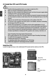
... the following guidelines before installing the memory to install the memory : ■ Make sure that the motherboard supports the memory. When memory is installed, the BIOS will automatically check the memory in only one direction. A memory module can be installed in your system. Dual Channel Memory Configuration This motherboard provides two...
... the following guidelines before installing the memory to install the memory : ■ Make sure that the motherboard supports the memory. When memory is installed, the BIOS will automatically check the memory in only one direction. A memory module can be installed in your system. Dual Channel Memory Configuration This motherboard provides two...
English Manual.
Page 20
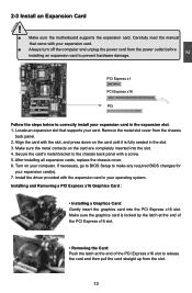
... the power outlet before installing an expansion card to prevent hardware damage. After installing all expansion cards, replace the chassis cover. 6. If necessary, go to BIOS Setup to the chassis back panel with the expansion card in your computer. PCI Express x1 PCI Express x16 PCI Follow the steps below to...
... the power outlet before installing an expansion card to prevent hardware damage. After installing all expansion cards, replace the chassis cover. 6. If necessary, go to BIOS Setup to the chassis back panel with the expansion card in your computer. PCI Express x1 PCI Express x16 PCI Follow the steps below to...

English Manual.
Page 24
.... Another 3-pin NB fan connector is used for S/PDIF output. The fan speed can be controlled and monitored in "PC Health Status" section of the BIOS Setup. 2 S/PDIF OUT Connector : SPDIF_OUT The connector is optional. +5V 1 EMPTY 2 SPDIF_OUT 3 GND 4 SPDIF_OUT GND POWER SENSE CONTROL CPU_FAN/SYS_FAN 17...
.... Another 3-pin NB fan connector is used for S/PDIF output. The fan speed can be controlled and monitored in "PC Health Status" section of the BIOS Setup. 2 S/PDIF OUT Connector : SPDIF_OUT The connector is optional. +5V 1 EMPTY 2 SPDIF_OUT 3 GND 4 SPDIF_OUT GND POWER SENSE CONTROL CPU_FAN/SYS_FAN 17...
English Manual.
Page 25
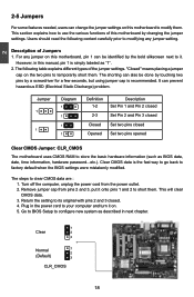
... needed, users can change the jumper settings on this motherboard to store the basic hardware information (such as BIOS data, date, time information, hardware password...etc.). Go to BIOS Setup to clear CMOS data are : 1. Description of the jumper settings. The following content carefully prior to... factory default when the BIOS settings were mistakenly modified. The steps to configure new system as "1". 2. Users should read the following table explains different types ...
... needed, users can change the jumper settings on this motherboard to store the basic hardware information (such as BIOS data, date, time information, hardware password...etc.). Go to BIOS Setup to clear CMOS data are : 1. Description of the jumper settings. The following content carefully prior to... factory default when the BIOS settings were mistakenly modified. The steps to configure new system as "1". 2. Users should read the following table explains different types ...

English Manual.
Page 26
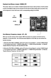
At the same time, a corresponding setting must not exceed the power supply capability (+5VSB) whether under normal condition or in BIOS as below: Set "CMOS Setup" -> "Power Management Setup" ->"Power Management Events" -> "USB KB Wake-Up From S3" to "Enabled". 1 +5V 2 (Default) 3 1 +5VSB 2 3 USBPW1357_1/ USBPW0246_1 ! ■ ...
At the same time, a corresponding setting must not exceed the power supply capability (+5VSB) whether under normal condition or in BIOS as below: Set "CMOS Setup" -> "Power Management Setup" ->"Power Management Events" -> "USB KB Wake-Up From S3" to "Enabled". 1 +5V 2 (Default) 3 1 +5VSB 2 3 USBPW1357_1/ USBPW0246_1 ! ■ ...
English Manual.
Page 27
... Status 1 Status 2 JP1 1 1 1 JP2 1 1 1 20 At the same time, the overclock bound depend on the keyboard or move the mouse, and a corresponding setting in the BIOS. 1 +5V 2 (Default) 3 1 +5VSB 2 3 KB/MS_PW Over Memory Frequency Jumper: JP1, JP2 When you to enable or disable keyboard and mouse wake-up feature. Set the...
... Status 1 Status 2 JP1 1 1 1 JP2 1 1 1 20 At the same time, the overclock bound depend on the keyboard or move the mouse, and a corresponding setting in the BIOS. 1 +5V 2 (Default) 3 1 +5VSB 2 3 KB/MS_PW Over Memory Frequency Jumper: JP1, JP2 When you to enable or disable keyboard and mouse wake-up feature. Set the...
English Manual.
Page 28
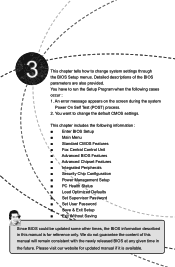
... Test (POST) process. 2. You have to change system settings through the BIOS Setup menus. This chapter includes the following cases occur : 1. We do not guarantee the content of the BIOS parameters are also provided. Please visit our website for reference only. You want... to run the Setup Program when the following information : ■ Enter BIOS Setup ■ Main Menu ■ Standard CMOS Features ■ Fox Central Control Unit ■ Advanced BIOS Features ■ Advanced Chipset Features ■ Integrated Peripherals ■ Security Chip Configuration ■...
... Test (POST) process. 2. You have to change system settings through the BIOS Setup menus. This chapter includes the following cases occur : 1. We do not guarantee the content of the BIOS parameters are also provided. Please visit our website for reference only. You want... to run the Setup Program when the following information : ■ Enter BIOS Setup ■ Main Menu ■ Standard CMOS Features ■ Fox Central Control Unit ■ Advanced BIOS Features ■ Advanced Chipset Features ■ Integrated Peripherals ■ Security Chip Configuration ■...
English Manual.
Page 29
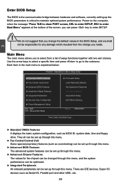
...Fox Central Control Unit Some special proprietary features (such as overclocking) can be set up through this menu. ► Advanced BIOS Features The advanced system features can be set up through this menu. We do not suggest that you change you to maintain... and press to go to enter SETUP. ! AwardBIOS CMOS Setup Utility ► Standard CMOS Features ► Fox Central Control Unit ► Advanced BIOS Features ► Advanced Chipset Features ► Integrated Peripherals ► Security Chip Configuration ► Power Management Setup Esc : Quit F10 : Save &...
...Fox Central Control Unit Some special proprietary features (such as overclocking) can be set up through this menu. ► Advanced BIOS Features The advanced system features can be set up through this menu. We do not suggest that you change you to maintain... and press to go to enter SETUP. ! AwardBIOS CMOS Setup Utility ► Standard CMOS Features ► Fox Central Control Unit ► Advanced BIOS Features ► Advanced Chipset Features ► Integrated Peripherals ► Security Chip Configuration ► Power Management Setup Esc : Quit F10 : Save &...
English Manual.
Page 30
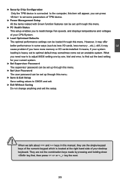
What you need now is to adjust BIOS setting one , trial and error, to find out the best setting for your current system. ► Set Supervisor Password The supervisor password can be set ...
What you need now is to adjust BIOS setting one , trial and error, to find out the best setting for your current system. ► Set Supervisor Password The supervisor password can be set ...
English Manual.
Page 31
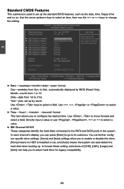
...- Month-month from Sun. Use , keys to the PATA and SATA ports in .] Halt On [All , But Keyboard] Installed Memory 1024M BIOS ID G31M04-GA20.F1.P.04 Move Enter:Select +/-/PU/PD:Value F10:Save ESC:Exit F1:General Help F5: Previous Values F7: Optimized Defaults &#...9658; Date - Year-year, set up by BIOS (Read Only). Use , , or to select a value. ► Time - : : format This item allows you to enable or disable this drive....
...- Month-month from Sun. Use , keys to the PATA and SATA ports in .] Halt On [All , But Keyboard] Installed Memory 1024M BIOS ID G31M04-GA20.F1.P.04 Move Enter:Select +/-/PU/PD:Value F10:Save ESC:Exit F1:General Help F5: Previous Values F7: Optimized Defaults &#...9658; Date - Year-year, set up by BIOS (Read Only). Use , , or to select a value. ► Time - : : format This item allows you to enable or disable this drive....
English Manual.
Page 32
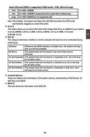
... ► Installed Memory These are Display-Only information of the system memory, determined by POST(Power On Self Test) of the BIOS. ► BIOS ID This item shows the information of the BIOS ID. 25 All Errors No Errors All, But Keyboard All, But Diskette All, But Disk/Key Whenever the... stop for any errors that may be prompted. The system boot will stop for a diskette error; but it will be detected. 3 Award (Phoenix) BIOS is detected during powering up. The system boot will stop for a keyboard error; It can detect the hard disk and select the HDD mode automatically.
... ► Installed Memory These are Display-Only information of the system memory, determined by POST(Power On Self Test) of the BIOS. ► BIOS ID This item shows the information of the BIOS ID. 25 All Errors No Errors All, But Keyboard All, But Diskette All, But Disk/Key Whenever the... stop for any errors that may be prompted. The system boot will stop for a diskette error; but it will be detected. 3 Award (Phoenix) BIOS is detected during powering up. The system boot will stop for a keyboard error; It can detect the hard disk and select the HDD mode automatically.
English Manual.
Page 33
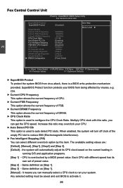
...PD:Value F10:Save ESC:Exit F1:General Help F5: Previous Values F7: Optimized Defaults ► SuperBIOS-Protect To protect the system BIOS from being affected by this item. CIH. ► Current CPU Frequency This option shows the current frequency of CPU. ► ... as [Step 1]. [Manual] - Any selected setting must be saved and exit BIOS to run your BIOS from virus attack, there is overclocked by a BIOS preset value. SuperBIOS Protect function protects your system. CPU is a BIOS write-protection mechanism provided. It means you can manually select a CPU clock to activate...
...PD:Value F10:Save ESC:Exit F1:General Help F5: Previous Values F7: Optimized Defaults ► SuperBIOS-Protect To protect the system BIOS from being affected by this item. CIH. ► Current CPU Frequency This option shows the current frequency of CPU. ► ... as [Step 1]. [Manual] - Any selected setting must be saved and exit BIOS to run your BIOS from virus attack, there is overclocked by a BIOS preset value. SuperBIOS Protect function protects your system. CPU is a BIOS write-protection mechanism provided. It means you can manually select a CPU clock to activate...
English Manual.
Page 36
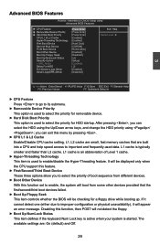
AwardBIOS CMOS Setup Utility Advanced BIOS Features ► CPU Feature ► Removable Device Priority ► Hard Disk Boot Priority CPU L1 & L2 Cache Hyper-...small, fast memory caches that the first/second/third boot devices failed. ► Boot Up Floppy Seek This item controls whether the BIOS will appear an error message. L1 cache is an abbreviation of boot sequence from some other devices provided that are built into a.... ► Hyper-Threading Technology This item is used data. L1, L2 cache are : On (default) and Off. 29 Advanced BIOS Features Phoenix -
AwardBIOS CMOS Setup Utility Advanced BIOS Features ► CPU Feature ► Removable Device Priority ► Hard Disk Boot Priority CPU L1 & L2 Cache Hyper-...small, fast memory caches that the first/second/third boot devices failed. ► Boot Up Floppy Seek This item controls whether the BIOS will appear an error message. L1 cache is an abbreviation of boot sequence from some other devices provided that are built into a.... ► Hyper-Threading Technology This item is used data. L1, L2 cache are : On (default) and Off. 29 Advanced BIOS Features Phoenix -
English Manual.
Page 38
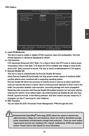
Should be met, including CPU, chipset, motherboard, BIOS and operation system. This item is used to enable/disable the C1E support. ► Execute Disable Bit This item is a feature which can free IT ...
Should be met, including CPU, chipset, motherboard, BIOS and operation system. This item is used to enable/disable the C1E support. ► Execute Disable Bit This item is a feature which can free IT ...
English Manual.
Page 39
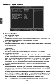
...► PEG/Onchip VGA Control This option is used to the operating system for VGA/ SVGA graphics. Advanced Chipset Features Phoenix - This BIOS option allows you to ensure the most efficient use by the operating system. The amount of the main system memory, which may result.... this memory area, a system error may improve performance. AwardBIOS CMOS Setup Utility Advanced Chipset Features ► PCI Express Root Port Func System BIOS Cacheable Memory Hole At 15M-16M [Press Enter] Item Help [Enabled] [Disabled] Menu Level ► ** VGA Setting ** PEG/Onchip ...
...► PEG/Onchip VGA Control This option is used to the operating system for VGA/ SVGA graphics. Advanced Chipset Features Phoenix - This BIOS option allows you to ensure the most efficient use by the operating system. The amount of the main system memory, which may result.... this memory area, a system error may improve performance. AwardBIOS CMOS Setup Utility Advanced Chipset Features ► PCI Express Root Port Func System BIOS Cacheable Memory Hole At 15M-16M [Press Enter] Item Help [Enabled] [Disabled] Menu Level ► ** VGA Setting ** PEG/Onchip ...
English Manual.
Page 42
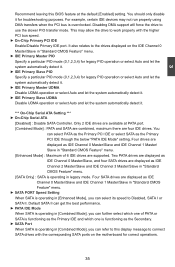
... are supported. Two PATA drives are displayed as IDE Channel 0 Master/Slave, and four SATA drives are four IDE drives. You can refer to this BIOS feature at PATA port. [Combined Mode] : PATA and SATA are combined, maximum there are displayed as the Primary PCI IDE through the below "PATA IDE...
... are supported. Two PATA drives are displayed as IDE Channel 0 Master/Slave, and four SATA drives are four IDE drives. You can refer to this BIOS feature at PATA port. [Combined Mode] : PATA and SATA are combined, maximum there are displayed as the Primary PCI IDE through the below "PATA IDE...
English Manual.
Page 45
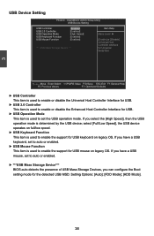
...], the USB device operates on full/low speed. ► USB Keyboard Function This item is used to auto or enabled. ► ***USB Mass Storage Device*** BIOS auto detects the presence of USB Mass Storage Devices, you have a USB mouse, set to auto or enabled. ► USB Mouse Function This item is...
...], the USB device operates on full/low speed. ► USB Keyboard Function This item is used to auto or enabled. ► ***USB Mass Storage Device*** BIOS auto detects the presence of USB Mass Storage Devices, you have a USB mouse, set to auto or enabled. ► USB Mouse Function This item is...
English Manual.
Page 47
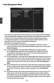
...- The S4 sleeping state is the lowest power, longest wake latency sleeping state supported by the OS (for initial boot operations within the BIOS to distinguish whether or not the boot is maintained. (also called Power On Suspend) S2 - Platform context is going to wake from the... called Suspend to allow for example, Windows2000 or WindowsXP). Software uses a different state value to distinguish between an operating system and the BIOS. In other words, it is an open industry standard that defines power and configuration management interfaces between the S5 state and the S4 ...
...- The S4 sleeping state is the lowest power, longest wake latency sleeping state supported by the OS (for initial boot operations within the BIOS to distinguish whether or not the boot is maintained. (also called Power On Suspend) S2 - Platform context is going to wake from the... called Suspend to allow for example, Windows2000 or WindowsXP). Software uses a different state value to distinguish between an operating system and the BIOS. In other words, it is an open industry standard that defines power and configuration management interfaces between the S5 state and the S4 ...


