
Service Manual
Page 4
... Appendix. CHAPTER 2.OPERATING PRINCIPLES Describes the theory of electrical and mechanical operations of the printer. May indicate an operating or maintenance procedure, practice or condition that is necessary to...of possible danger present during a procedure or an action. CHAPTER 5.ADJUSTMENT Provides Epson-approved methods for disassembling and assembling the product. APPENDIX Provides the following additional information...Electrical circuit boards schematics • Exploded diagram & Parts List Symbols Used in damage to the precautions on a specific topic or to accomplish a task...
... Appendix. CHAPTER 2.OPERATING PRINCIPLES Describes the theory of electrical and mechanical operations of the printer. May indicate an operating or maintenance procedure, practice or condition that is necessary to...of possible danger present during a procedure or an action. CHAPTER 5.ADJUSTMENT Provides Epson-approved methods for disassembling and assembling the product. APPENDIX Provides the following additional information...Electrical circuit boards schematics • Exploded diagram & Parts List Symbols Used in damage to the precautions on a specific topic or to accomplish a task...

Service Manual
Page 10
EPSON Stylus Pro 7600/9600 Revision A 5.2.2.7 CSIC 227 5.2.2.8 Actuator 229 5.2.2.9 Actuator 2 229 5.2.3 Adjustment 230 5.2.3.1 Rear AD Adjustment 231 5.2.3.2 Edge AD Adjustment 232 5.2.3.3 Input Rank 233 5.2.3.4 Write D/A Value 236 ...Maintenance Items During Service Operations 279 6.2 Lubrication and Glue 280 6.2.1 Lubricating the CR Guide Rail 280 Chapter 7 Appendix 7.1 Connectors ...282 7.2 Component Layout 285 7.3 Circuit Diagrams 286 7.4 Exploded Diagrams 292 7.5 ASP List (Parts List 317 7.5.1 ASP List for Stylus Pro 7600 317 7.5.2 ASP List for Stylus Pro 9600 320 10
EPSON Stylus Pro 7600/9600 Revision A 5.2.2.7 CSIC 227 5.2.2.8 Actuator 229 5.2.2.9 Actuator 2 229 5.2.3 Adjustment 230 5.2.3.1 Rear AD Adjustment 231 5.2.3.2 Edge AD Adjustment 232 5.2.3.3 Input Rank 233 5.2.3.4 Write D/A Value 236 ...Maintenance Items During Service Operations 279 6.2 Lubrication and Glue 280 6.2.1 Lubricating the CR Guide Rail 280 Chapter 7 Appendix 7.1 Connectors ...282 7.2 Component Layout 285 7.3 Circuit Diagrams 286 7.4 Exploded Diagrams 292 7.5 ASP List (Parts List 317 7.5.1 ASP List for Stylus Pro 7600 317 7.5.2 ASP List for Stylus Pro 9600 320 10

Service Manual
Page 152
...diagrams in the appendix. 4.1.1 Precautions Before proceeding with descriptions added to particulars specific to unplug the power cord from the reversed procedure of the CR motor and PF motor. Before servicing, unless otherwise stated, be sure to Stylus Pro 9600. Do not put it near fire. EPSON Stylus Pro 7600/9600... circuit board: • Keep the battery away from any part of Stylus Pro 7600/9600. If you are described under the heading "Warning". Chips for... safety, you must keep the power supplied to turn the printer off and wait several seconds first and then unplug the power...
...diagrams in the appendix. 4.1.1 Precautions Before proceeding with descriptions added to particulars specific to unplug the power cord from the reversed procedure of the CR motor and PF motor. Before servicing, unless otherwise stated, be sure to Stylus Pro 9600. Do not put it near fire. EPSON Stylus Pro 7600/9600... circuit board: • Keep the battery away from any part of Stylus Pro 7600/9600. If you are described under the heading "Warning". Chips for... safety, you must keep the power supplied to turn the printer off and wait several seconds first and then unplug the power...

Service Manual
Page 158
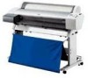
EPSON Stylus Pro 7600/9600 4.2 Removing the Panel Unit and Housing This sections describes the removal procedure for an illustration of the housing parts. Housing Part Diagram Disassembly & Assembly Removing the Panel Unit and Housing 158 Revision A 4.2.5 H Top Cover (p.165) 4.2.3 L Side Cover (p.163) 4.2.8 Roll Paper Cover (p.169) 4.2.2 R Side Cover (p.160) 4.2.4 I/H Cover (p.164) 4.2.9 Front Cover (p.170) 4.2.7 Paper Guide L2 (p.168) Paper Set Lever 4.2.1 Panel Unit (p.159) Figure 4-3. See below for printer housing parts.
EPSON Stylus Pro 7600/9600 4.2 Removing the Panel Unit and Housing This sections describes the removal procedure for an illustration of the housing parts. Housing Part Diagram Disassembly & Assembly Removing the Panel Unit and Housing 158 Revision A 4.2.5 H Top Cover (p.165) 4.2.3 L Side Cover (p.163) 4.2.8 Roll Paper Cover (p.169) 4.2.2 R Side Cover (p.160) 4.2.4 I/H Cover (p.164) 4.2.9 Front Cover (p.170) 4.2.7 Paper Guide L2 (p.168) Paper Set Lever 4.2.1 Panel Unit (p.159) Figure 4-3. See below for printer housing parts.

