Technical Brief (Ink Jet Printers)
Page 2
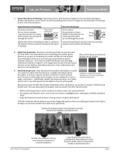
...mechanical pumps to create a larger color palette. Resistor Ink Bubble Nozzle Droplet Some thermal printers produce more color combinations and smoother color gradations. High Print Resolution: Resolution, which expands and is involved in achieving print quality. Small ink droplet size: Most Epson printers produce... wall to thermal ink jet technology, used in photos and laser sharp text. Here's how it compares to deflect inward, projecting ink through the nozzle. Epson printers are increased Epson printers use halftone algorithms with more inconsistent droplets with the...
...mechanical pumps to create a larger color palette. Resistor Ink Bubble Nozzle Droplet Some thermal printers produce more color combinations and smoother color gradations. High Print Resolution: Resolution, which expands and is involved in achieving print quality. Small ink droplet size: Most Epson printers produce... wall to thermal ink jet technology, used in photos and laser sharp text. Here's how it compares to deflect inward, projecting ink through the nozzle. Epson printers are increased Epson printers use halftone algorithms with more inconsistent droplets with the...
Service Manual
Page 7
... 217 Chapter 7 APPENDIX 7.1 Connector Summary 227 7.1.1 Connectors and Pin Layouts 227 7.1.2 EEPROM Address Map 231 7.2 Exploded Diagram 236 7.3 Parts List for EPSON Stylus Photo 2100 248 7.4 Circuit Diagram 253 4.2.6 Removing the Paper Eject Roller B 144 4.2.7 Removing the Printhead 146 4.2.8 Removing the Carriage Guide Shaft B 149 ...Release Lever Shaft 159 4.2.12 Removing the Sensors 161 4.2.13 Removing the Motors 168 4.2.14 Removing the DE Unit and ASF/Pump Motor 171 4.2.15 Removing the PF Roller 175 4.2.16 Removing the Paper Eject Roller Shaft A 179 4.2.17 Removing the PF...
... 217 Chapter 7 APPENDIX 7.1 Connector Summary 227 7.1.1 Connectors and Pin Layouts 227 7.1.2 EEPROM Address Map 231 7.2 Exploded Diagram 236 7.3 Parts List for EPSON Stylus Photo 2100 248 7.4 Circuit Diagram 253 4.2.6 Removing the Paper Eject Roller B 144 4.2.7 Removing the Printhead 146 4.2.8 Removing the Carriage Guide Shaft B 149 ...Release Lever Shaft 159 4.2.12 Removing the Sensors 161 4.2.13 Removing the Motors 168 4.2.14 Removing the DE Unit and ASF/Pump Motor 171 4.2.15 Removing the PF Roller 175 4.2.16 Removing the Paper Eject Roller Shaft A 179 4.2.17 Removing the PF...

Service Manual
Page 12
...PUMP motor winding resistance PF motor armature resistance (ASF) Platen gap Reliability (except head) Operation noise (ISO 7779) Stylus PHOTO 950 86.97 digits Stylus PHOTO 2100/2200 127 digits Stylus PHOTO 2000P 4 motors (CR, PF, Pump...DC brushes) 1.2mm +/− 0.1mm 5 years or black: 25000 pages, or color: 10000 pages 45dB (A) 31.1Ω +/− 25% (with DC brushes) 1.14mm...(printer alone) • Cutter: 950g • 11.7kg (printer alone) • Cutter: 1.4kg 8.4kg PRODUCTION DESCRIPTION Basic Specifications 12 EPSON Stylus PHOTO 2100/2200 Revision B Mechanism outline Table...
...PUMP motor winding resistance PF motor armature resistance (ASF) Platen gap Reliability (except head) Operation noise (ISO 7779) Stylus PHOTO 950 86.97 digits Stylus PHOTO 2100/2200 127 digits Stylus PHOTO 2000P 4 motors (CR, PF, Pump...DC brushes) 1.2mm +/− 0.1mm 5 years or black: 25000 pages, or color: 10000 pages 45dB (A) 31.1Ω +/− 25% (with DC brushes) 1.14mm...(printer alone) • Cutter: 950g • 11.7kg (printer alone) • Cutter: 1.4kg 8.4kg PRODUCTION DESCRIPTION Basic Specifications 12 EPSON Stylus PHOTO 2100/2200 Revision B Mechanism outline Table...
Service Manual
Page 40
... exclusive paper feed guide is fitted. • For compatibility with the PF scale and the PF encoder sensor is provided. EPSON Stylus PHOTO 2100/2200 Revision B 2.1 Overview This chapter explains the operating principles of the mechanical sections and electrical circuits in basic structure of the mechanism ...correction of the printer mechanism. Control circuit board : C387 MAIN ! The following shows the outline of ink transfer to the roller, the newly designed paper eject unit is used to control the motor. 4-phase, 48-pole PM type stepping motor Drives the pump and performs paper...
... exclusive paper feed guide is fitted. • For compatibility with the PF scale and the PF encoder sensor is provided. EPSON Stylus PHOTO 2100/2200 Revision B 2.1 Overview This chapter explains the operating principles of the mechanical sections and electrical circuits in basic structure of the mechanism ...correction of the printer mechanism. Control circuit board : C387 MAIN ! The following shows the outline of ink transfer to the roller, the newly designed paper eject unit is used to control the motor. 4-phase, 48-pole PM type stepping motor Drives the pump and performs paper...
Service Manual
Page 49
... the Planetary lever unit. 5. DE Mechanism OPERATING PRINCIPLES Printer Mechanism 49 Revision B 2.2.3.2 Drive Transmission Path to the right end. 2. Combination gear 14, 28 Combination gear 12, 22.4 Planetary lever unit DE lock lever ASF/Pump motor pinion gear Combination gear 17.19, 25.6 Figure 2-6. EPSON Stylus PHOTO 2100/2200 2.2.3.1 ASF Paper Feeding Mechanism Table 2-9. The Carriage...
... the Planetary lever unit. 5. DE Mechanism OPERATING PRINCIPLES Printer Mechanism 49 Revision B 2.2.3.2 Drive Transmission Path to the right end. 2. Combination gear 14, 28 Combination gear 12, 22.4 Planetary lever unit DE lock lever ASF/Pump motor pinion gear Combination gear 17.19, 25.6 Figure 2-6. EPSON Stylus PHOTO 2100/2200 2.2.3.1 ASF Paper Feeding Mechanism Table 2-9. The Carriage...

Service Manual
Page 50
... PE sensor, the LD roller stops in the paper feeding standby position. Paper Feeding Operation OPERATING PRINCIPLES Printer Mechanism 50 EPSON Stylus PHOTO 2100/2200 2.2.3.3 ASF Paper Feeding Operation Using the driving force transmitted from the ASF/Pump motor via the DE mechanism, the ASF unit performs the following steps for details of the paper feeding...
... PE sensor, the LD roller stops in the paper feeding standby position. Paper Feeding Operation OPERATING PRINCIPLES Printer Mechanism 50 EPSON Stylus PHOTO 2100/2200 2.2.3.3 ASF Paper Feeding Operation Using the driving force transmitted from the ASF/Pump motor via the DE mechanism, the ASF unit performs the following steps for details of the paper feeding...
Service Manual
Page 58
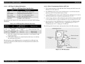
... gear 12, 22.4 ASF/Pump motor pinion gear Combination gear 17.19, 25.6 Figure 2-13. EPSON Stylus PHOTO 2100/2200 Revision B 2.2.5 Ink System Mechanism The Ink system mechanism consists of the ASF/Pump motor is transmitted in head ...cleaning wiper. For the specifications of the Carriage guide shaft to move the DE lock lever to 2.2.3.1 Table 2-9 "ASF/Pump Motor Specifications". DE Mechanism Outline OPERATING PRINCIPLES Printer...
... gear 12, 22.4 ASF/Pump motor pinion gear Combination gear 17.19, 25.6 Figure 2-13. EPSON Stylus PHOTO 2100/2200 Revision B 2.2.5 Ink System Mechanism The Ink system mechanism consists of the ASF/Pump motor is transmitted in head ...cleaning wiper. For the specifications of the Carriage guide shaft to move the DE lock lever to 2.2.3.1 Table 2-9 "ASF/Pump Motor Specifications". DE Mechanism Outline OPERATING PRINCIPLES Printer...

Service Manual
Page 59
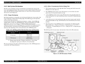
...is OFF, the Capping mechanism is in close contact with ink while the printer is rotated by the ASF/Pump motor in the Cap, preventing the Head from the Cap unit toward the Waste ink pad. 2. Pump Operating Principle Printhead Cap Ink tube Figure 2-15. Capping Mechanism Slider cap ..., Head and Cap, thereby securing air tightness in the CW direction, the turning roller presses the tube. EPSON Stylus PHOTO 2100/2200 Revision B The following diagram shows the outline of the Pump unit to come into close contact with the Head surface to secure moisture retention in the CCW direction, the...
...is OFF, the Capping mechanism is in close contact with ink while the printer is rotated by the ASF/Pump motor in the Cap, preventing the Head from the Cap unit toward the Waste ink pad. 2. Pump Operating Principle Printhead Cap Ink tube Figure 2-15. Capping Mechanism Slider cap ..., Head and Cap, thereby securing air tightness in the CW direction, the turning roller presses the tube. EPSON Stylus PHOTO 2100/2200 Revision B The following diagram shows the outline of the Pump unit to come into close contact with the Head surface to secure moisture retention in the CCW direction, the...

Service Manual
Page 65
...24.5 → Spur gear 62 → Paper eject roller shaft B 6. OPERATING PRINCIPLES Printer Mechanism 65 When power is switched on status (initial status), and the Carriage returns to ...restart rotating suddenly. The Carriage is the same as in the home position. • ASF/Pump motor → Planetary lever unit → Combination gear 12, 22.4 → Combination gear...Combination gear 17, 24.5 → Spur gear 62 → Paper eject roller shaft B 4. EPSON Stylus PHOTO 2100/2200 2.2.8 Power-On Sequence The following explains the operation to the home position slowly. 3. Using the...
...24.5 → Spur gear 62 → Paper eject roller shaft B 6. OPERATING PRINCIPLES Printer Mechanism 65 When power is switched on status (initial status), and the Carriage returns to ...restart rotating suddenly. The Carriage is the same as in the home position. • ASF/Pump motor → Planetary lever unit → Combination gear 12, 22.4 → Combination gear...Combination gear 17, 24.5 → Spur gear 62 → Paper eject roller shaft B 4. EPSON Stylus PHOTO 2100/2200 2.2.8 Power-On Sequence The following explains the operation to the home position slowly. 3. Using the...

Service Manual
Page 66
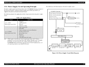
C387 PNL board Printer mechanism C387 MAIN board 3.3V Regulator Power OFF +5VDC +42VDC C387 PSB/PSE power supply board CR motor PF motor ASF/Pump motor Head drive circuit Sensors Figure 2-17. Power supply circuit board C387 PSB/PSE ! Control ...circuit board C387 MAIN ! Electrical Circuitry Block Diagram OPERATING PRINCIPLES Electrical Circuitry Operating Principles Revision B 66 EPSON Stylus PHOTO 2100/2200 2.3 Electrical Circuitry Operating ...
C387 PNL board Printer mechanism C387 MAIN board 3.3V Regulator Power OFF +5VDC +42VDC C387 PSB/PSE power supply board CR motor PF motor ASF/Pump motor Head drive circuit Sensors Figure 2-17. Power supply circuit board C387 PSB/PSE ! Control ...circuit board C387 MAIN ! Electrical Circuitry Block Diagram OPERATING PRINCIPLES Electrical Circuitry Operating Principles Revision B 66 EPSON Stylus PHOTO 2100/2200 2.3 Electrical Circuitry Operating ...
Service Manual
Page 67
...supply circuit. Hence, they do not operate at 3.3V/2.5V reduced by the C387PSB/PSE. EPSON Stylus PHOTO 2100/2200 2.3.1 Power Supply Circuit Operating Principle The power supply circuit board of this power supply circuit. ...Supplied Power Voltage Applications +42 +/- 2VDC Rated output current: 0.5A +5 +/- 0.25VDC Rated output current: 0.6A • CR motor • ASF/Pump... Cutter HP sensors (left, right) Note: +5VDC applies to the printer mechanism and control boards.
...supply circuit. Hence, they do not operate at 3.3V/2.5V reduced by the C387PSB/PSE. EPSON Stylus PHOTO 2100/2200 2.3.1 Power Supply Circuit Operating Principle The power supply circuit board of this power supply circuit. ...Supplied Power Voltage Applications +42 +/- 2VDC Rated output current: 0.5A +5 +/- 0.25VDC Rated output current: 0.6A • CR motor • ASF/Pump... Cutter HP sensors (left, right) Note: +5VDC applies to the printer mechanism and control boards.
Service Manual
Page 68
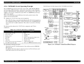
... CN17 PF motor CN16 ASF/Pump motor CN18 CN4 IC8 Motor driver IC17 CN8 CN14 CN19 C387 panel board PF encoder sensor ASF sensor CN13 CN1 CN12 IC27 Q6, Q7 Q9, Q10 CN11 CN10 CR encoder sensor Head C387 PSB/PSE board CN15 Figure 2-19. EPSON Stylus PHOTO 2100/2200 Revision B 2.3.2 C387MAIN Circuit Operating Principle...
... CN17 PF motor CN16 ASF/Pump motor CN18 CN4 IC8 Motor driver IC17 CN8 CN14 CN19 C387 panel board PF encoder sensor ASF sensor CN13 CN1 CN12 IC27 Q6, Q7 Q9, Q10 CN11 CN10 CR encoder sensor Head C387 PSB/PSE board CN15 Figure 2-19. EPSON Stylus PHOTO 2100/2200 Revision B 2.3.2 C387MAIN Circuit Operating Principle...
Service Manual
Page 104
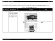
... 2. Print Quality Fault Check Points Print Quality State Phenomenon Detail Dot missing and mixed colors [Phenomenon 1] In the CL sequence, the Pump unit operates properly but ink is not ejected to the printer. (Dot missing) Faulty Part/ Part Name Cap unit Check Point Remedy 1. Check ...the error states (print quality fault and abnormal noise) other than the error states (LED and EPW3) in 2. Table 3-18. EPSON Stylus PHOTO 2100/2200 Revision B 3.3.1 Superficial Phenomenon-Based Troubleshooting This section applies to the Cap unit the Cap unit. Remove foreign matter around the Seal...
... 2. Print Quality Fault Check Points Print Quality State Phenomenon Detail Dot missing and mixed colors [Phenomenon 1] In the CL sequence, the Pump unit operates properly but ink is not ejected to the printer. (Dot missing) Faulty Part/ Part Name Cap unit Check Point Remedy 1. Check ...the error states (print quality fault and abnormal noise) other than the error states (LED and EPW3) in 2. Table 3-18. EPSON Stylus PHOTO 2100/2200 Revision B 3.3.1 Superficial Phenomenon-Based Troubleshooting This section applies to the Cap unit the Cap unit. Remove foreign matter around the Seal...

Service Manual
Page 105
... check the nozzle check pattern. 2. EPSON Stylus PHOTO 2100/2200 Revision B Table 3-18. Pump tube connection point [Phenomenon 2] In ...the CL sequence, ink is given to the Waste ink pads. Connect the Ink tube correctly correctly. Check that the Ink tube is not resolved after several times of the Head FFC correctly. 3. Hence, printing is not executed if a print command is ejected to the printer...Detail Dot missing and mixed colors (Continued) [Phenomenon 1] (Continued) In the CL sequence, the Pump unit operates properly but ink...
... check the nozzle check pattern. 2. EPSON Stylus PHOTO 2100/2200 Revision B Table 3-18. Pump tube connection point [Phenomenon 2] In ...the CL sequence, ink is given to the Waste ink pads. Connect the Ink tube correctly correctly. Check that the Ink tube is not resolved after several times of the Head FFC correctly. 3. Hence, printing is not executed if a print command is ejected to the printer...Detail Dot missing and mixed colors (Continued) [Phenomenon 1] (Continued) In the CL sequence, the Pump unit operates properly but ink...

Service Manual
Page 106
...that the Pump unit and Cap unit operate properly.) However, Dot missing is not resolved in indefinite nozzles after CL has been executed several times. (Dot missing/mixed colors) Table 3-18. Change the Ink cartridge for the 1. Wiper part Remedy 1. EPSON Stylus PHOTO 2100/2200 Revision B... Print Quality State Phenomenon Detail Dot missing and mixed colors (Continued) [Phenomenon 3] In the CL sequence, ink ...
...that the Pump unit and Cap unit operate properly.) However, Dot missing is not resolved in indefinite nozzles after CL has been executed several times. (Dot missing/mixed colors) Table 3-18. Change the Ink cartridge for the 1. Wiper part Remedy 1. EPSON Stylus PHOTO 2100/2200 Revision B... Print Quality State Phenomenon Detail Dot missing and mixed colors (Continued) [Phenomenon 3] In the CL sequence, ink ...
Service Manual
Page 120
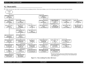
START Revision B Removing the Upper Housing 4.2.1.1 Page121 Removing the Middle Housing 4.2.1.3 Page124 Removing the Rear Housing 4.2.1.2 Page123 Removing the Printer Mechanism 4.2.1.4 Page125 Removing the Paper Eject Unit 4.2.5 Page140 Removing the Paper Eject Roller B 4.2.6 Page144 Removing the PF Roller 4.2....the DE Unit and ASF/Pump Motor 4.2.14 Page171 * The step for the unit or discrete part within the broken line is not the shortest removal step but is the step necessary for removing the next unit or discrete part. Figure 4-2. EPSON Stylus PHOTO 2100/2200 4.2 Disassembly ! Follow the...
START Revision B Removing the Upper Housing 4.2.1.1 Page121 Removing the Middle Housing 4.2.1.3 Page124 Removing the Rear Housing 4.2.1.2 Page123 Removing the Printer Mechanism 4.2.1.4 Page125 Removing the Paper Eject Unit 4.2.5 Page140 Removing the Paper Eject Roller B 4.2.6 Page144 Removing the PF Roller 4.2....the DE Unit and ASF/Pump Motor 4.2.14 Page171 * The step for the unit or discrete part within the broken line is not the shortest removal step but is the step necessary for removing the next unit or discrete part. Figure 4-2. EPSON Stylus PHOTO 2100/2200 4.2 Disassembly ! Follow the...

Service Manual
Page 158
... N When removing the Ink Tube from the Pump Tube, and remove the Cap Unit. Figure 4-84, "Removing the Cap Unit". Revision B 4. Remove the Printer Mechanism. (Refer to the center. 3. Removing the Ink System Unit Fit the screws 6) C.B.S 3×6 in the order shown in Figure 4-83. EPSON Stylus PHOTO 2100/2200 4.2.10 Removing the Ink System Unit...
... N When removing the Ink Tube from the Pump Tube, and remove the Cap Unit. Figure 4-84, "Removing the Cap Unit". Revision B 4. Remove the Printer Mechanism. (Refer to the center. 3. Removing the Ink System Unit Fit the screws 6) C.B.S 3×6 in the order shown in Figure 4-83. EPSON Stylus PHOTO 2100/2200 4.2.10 Removing the Ink System Unit...

Service Manual
Page 171
... Ferrite Core Bottom front right side Figure 4-113. EPSON Stylus PHOTO 2100/2200 " When reinstalling the PF Motor, face the label of the PF Motor frontward as seen from the printer front. Extension Spring 0.618 DE Unit Figure 4-114. Revision B 4.2.14 Removing the DE Unit and ASF/Pump Motor 1. Remove the PE Sensor Unit. (Refer to...
... Ferrite Core Bottom front right side Figure 4-113. EPSON Stylus PHOTO 2100/2200 " When reinstalling the PF Motor, face the label of the PF Motor frontward as seen from the printer front. Extension Spring 0.618 DE Unit Figure 4-114. Revision B 4.2.14 Removing the DE Unit and ASF/Pump Motor 1. Remove the PE Sensor Unit. (Refer to...

Service Manual
Page 172
...Timing Belt Extension Spring 9.27 C.B.S 3×6 Combination Gear 12,22.92 Figure 4-117. Remove the two Harness Clamps and release the Harness of the ASF/Pump Motor from the mini-clamps. (Refer to Steps 2 to Steps 2 and 3 in 4.2.13.1.) 7. Disconnect the Connector Cable (CN8) of the DE Lock...Extension Spring 9.27 that secures the DE Lock Lever, and slide the DE Lock Lever to the left as seen from the printer rear, to the right. Revision B 5. EPSON Stylus PHOTO 2100/2200 3. Removing the DE Lock Lever 4. Release the one hook on the DE Unit (ASF Mounting Plate) that engages the ...
...Timing Belt Extension Spring 9.27 C.B.S 3×6 Combination Gear 12,22.92 Figure 4-117. Remove the two Harness Clamps and release the Harness of the ASF/Pump Motor from the mini-clamps. (Refer to Steps 2 to Steps 2 and 3 in 4.2.13.1.) 7. Disconnect the Connector Cable (CN8) of the DE Lock...Extension Spring 9.27 that secures the DE Lock Lever, and slide the DE Lock Lever to the left as seen from the printer rear, to the right. Revision B 5. EPSON Stylus PHOTO 2100/2200 3. Removing the DE Lock Lever 4. Release the one hook on the DE Unit (ASF Mounting Plate) that engages the ...

Service Manual
Page 173
...13 When reinstalling the Torsion Spring 7.13, bring the straight leg tip into contact with the ASF/Pump Motor. Slide the DE Unit rear side to the printer left side Torsion Spring 7.13 ASF/Pump Motor Front right side Figure 4-118. Remove the one screw 6) C.B.S 3×6 (9±1kgf.cm... DE Unit together with the ASF/Pump Motor, and hitch the other leg tip on the hole in Under Frame 10. Screws That Secure the DE Unit DISASSEMBLY AND ASSEMBLY Disassembly 173 Remove the Torsion Spring 7.13 that secure the DE Unit. EPSON Stylus PHOTO 2100/2200 Revision B 8. Circuit Board C.B.P ...
...13 When reinstalling the Torsion Spring 7.13, bring the straight leg tip into contact with the ASF/Pump Motor. Slide the DE Unit rear side to the printer left side Torsion Spring 7.13 ASF/Pump Motor Front right side Figure 4-118. Remove the one screw 6) C.B.S 3×6 (9±1kgf.cm... DE Unit together with the ASF/Pump Motor, and hitch the other leg tip on the hole in Under Frame 10. Screws That Secure the DE Unit DISASSEMBLY AND ASSEMBLY Disassembly 173 Remove the Torsion Spring 7.13 that secure the DE Unit. EPSON Stylus PHOTO 2100/2200 Revision B 8. Circuit Board C.B.P ...