
Literature/Product Sheet
Page 1
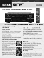
...This video transcoding technology lets you enjoy highest picture quality from all video gear connected to a theater's front speakers being placed behind the movie screen. The AVR-1905 features a Cinema Equalizer to correct these high-frequency components so that the sound is placed in a design ... images. • 3 Sets of Component Video Inputs The AVR-1905 is too strong. s On Screen Display The AVR-1905 lets you can customize the performance of monitor outputs (all of DENON's high-grade A/V receivers, the AVR-1905 lets you need to bring out the maximum potential of your...
...This video transcoding technology lets you enjoy highest picture quality from all video gear connected to a theater's front speakers being placed behind the movie screen. The AVR-1905 features a Cinema Equalizer to correct these high-frequency components so that the sound is placed in a design ... images. • 3 Sets of Component Video Inputs The AVR-1905 is too strong. s On Screen Display The AVR-1905 lets you can customize the performance of monitor outputs (all of DENON's high-grade A/V receivers, the AVR-1905 lets you need to bring out the maximum potential of your...
Literature/Product Sheet
Page 2
... a Select function that let you more accurately match the performance characteristics of the subwoofer to the main speaker system. NEW MODEL I N F O R M AT I O N AVR-1905 s Multi-Function Preset Memory Remote Controller with Glo-keys The supplied system remote controller features a large ...tape, stereo radio and stereo video sources into exciting surround sound, free of delay effects and unnatural artifacts, from other manufacturers s DENON's Latest Surround Technology Faithfully Recreates the Surround Sound Produced at 100 Hz s FM Section Tuning frequency range......... 87.5 - 107.9...
... a Select function that let you more accurately match the performance characteristics of the subwoofer to the main speaker system. NEW MODEL I N F O R M AT I O N AVR-1905 s Multi-Function Preset Memory Remote Controller with Glo-keys The supplied system remote controller features a large ...tape, stereo radio and stereo video sources into exciting surround sound, free of delay effects and unnatural artifacts, from other manufacturers s DENON's Latest Surround Technology Faithfully Recreates the Surround Sound Produced at 100 Hz s FM Section Tuning frequency range......... 87.5 - 107.9...
Owners Manual
Page 5
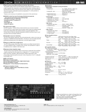
...; Moving the set To prevent short circuits or damaged wires in the STANDBY state, the apparatus is equipped with the connection cords. AUX terminal The AVR-1905/785's front panel is still connected on Check once again that all connections are proper and that the illustrations in a safe place. For heat dispersal..., leave at least 4 inch/10 cm of space between the top, back and sides of PRE OUT jacks, HEADPHONE jack and SPEAKER terminals The PRE OUT jacks, HEADPHONE jack and...
...; Moving the set To prevent short circuits or damaged wires in the STANDBY state, the apparatus is equipped with the connection cords. AUX terminal The AVR-1905/785's front panel is still connected on Check once again that all connections are proper and that the illustrations in a safe place. For heat dispersal..., leave at least 4 inch/10 cm of space between the top, back and sides of PRE OUT jacks, HEADPHONE jack and SPEAKER terminals The PRE OUT jacks, HEADPHONE jack and...

Owners Manual
Page 7
... Tape deck B Connecting a tape deck Connections for playback: Connect the tape deck's playback output jacks (LINE OUT or PB) to audio equipment with one speaker, connect the speaker to this unit's tape playback (CDR/TAPE IN) jacks using pin plug cords. NOTE: Only use them near a power transformer will result in the...
... Tape deck B Connecting a tape deck Connections for playback: Connect the tape deck's playback output jacks (LINE OUT or PB) to audio equipment with one speaker, connect the speaker to this unit's tape playback (CDR/TAPE IN) jacks using pin plug cords. NOTE: Only use them near a power transformer will result in the...
Owners Manual
Page 13
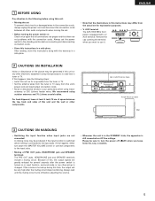
... level) jacks can be used to play a different program source in ZONE2 the same time. (See page 44) Extension jacks for future use. In this speaker for ZONE2. See page 29. (L) (R) L R Extension jacks for future use. ZONE2 Integrated pre-main amplifier or power amplifier B RC-617 INFRARED SENSOR OUTPUT + ...or pre-main (integrated) amplifier is connected, the ZONE2 output terminals can be used for MAIN ZONE. (See page 29) SURROUND BACK/MULTI ZONE SPEAKER SYSTEMS NOTE: • The settings must be changed to play a different program source in ZONE2 the same time. • ZONE2...
... level) jacks can be used to play a different program source in ZONE2 the same time. (See page 44) Extension jacks for future use. In this speaker for ZONE2. See page 29. (L) (R) L R Extension jacks for future use. ZONE2 Integrated pre-main amplifier or power amplifier B RC-617 INFRARED SENSOR OUTPUT + ...or pre-main (integrated) amplifier is connected, the ZONE2 output terminals can be used for MAIN ZONE. (See page 29) SURROUND BACK/MULTI ZONE SPEAKER SYSTEMS NOTE: • The settings must be changed to play a different program source in ZONE2 the same time. • ZONE2...
Owners Manual
Page 14
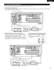
...;). Doing so could result in contact with adjacent terminals, with other speaker cord conductors, or with an impedance of 6 to 16 Ω/ohms can be activated if the set is cut off the power and contact a DENON service center. Turn off the power of this occur, please follow ...these steps: be connected for the set , then turn the power back on . Speaker Impedance • When speaker systems A and B are connected. When the protection circuit is...
...;). Doing so could result in contact with adjacent terminals, with other speaker cord conductors, or with an impedance of 6 to 16 Ω/ohms can be activated if the set is cut off the power and contact a DENON service center. Turn off the power of this occur, please follow ...these steps: be connected for the set , then turn the power back on . Speaker Impedance • When speaker systems A and B are connected. When the protection circuit is...
Owners Manual
Page 15
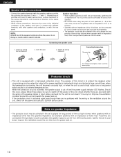
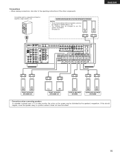
... placed near a TV or video monitor, the colors on the screen may be changed to a position where it does not have this speaker for subwoofer with one speaker, connect the speaker to the operating instructions of the other components. Connections • When making connections, also refer to SURR. BACK L CH. • The settings...
... placed near a TV or video monitor, the colors on the screen may be changed to a position where it does not have this speaker for subwoofer with one speaker, connect the speaker to the operating instructions of the other components. Connections • When making connections, also refer to SURR. BACK L CH. • The settings...
Owners Manual
Page 16
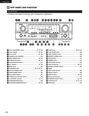
... ( ). #4 #3 #2 #1 #0 @9 @8 @7 @6 @5 @4 @3 @2 @1 @0 r u o !1 !3 q w e ty i !0 !2 !4 !5 !6 !7 !8 !9 q Power ON/STANDBY switch 21, 36, 58) w Power indicator 21, 36) e Power switch 21, 36) r Headphones jack (PHONES 40) t INPUT MODE button 37, 39) y SPEAKER A/B buttons 36, 61) u SURROUND BACK button 51) i EXT.
... ( ). #4 #3 #2 #1 #0 @9 @8 @7 @6 @5 @4 @3 @2 @1 @0 r u o !1 !3 q w e ty i !0 !2 !4 !5 !6 !7 !8 !9 q Power ON/STANDBY switch 21, 36, 58) w Power indicator 21, 36) e Power switch 21, 36) r Headphones jack (PHONES 40) t INPUT MODE button 37, 39) y SPEAKER A/B buttons 36, 61) u SURROUND BACK button 51) i EXT.
Owners Manual
Page 17
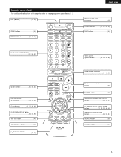
...) SURROUND PARAMETER/SYSTEM button 33, 34, 47) CH SELECT (channel select)/ ENTER button 19, 33, 34, 46, 48) SURROUND BACK/RETURN button 33, 34, 51) SPEAKER button 36) DIMMER button 41) 17 Remote control unit • For details on the functions of these parts, refer to the pages given in parentheses ( ).
...) SURROUND PARAMETER/SYSTEM button 33, 34, 47) CH SELECT (channel select)/ ENTER button 19, 33, 34, 46, 48) SURROUND BACK/RETURN button 33, 34, 51) SPEAKER button 36) DIMMER button 41) 17 Remote control unit • For details on the functions of these parts, refer to the pages given in parentheses ( ).
Owners Manual
Page 19
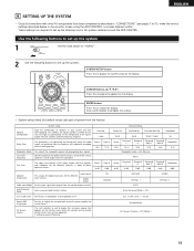
...in your system and their corresponding sizes (SMALL for regular speakers, LARGE for fullsize, full-range) to be output from the speakers and the frequency response. Set the frequency (Hz) below on the monitor screen using the AVR-1905/785's on the display. Auto Surround Mode Auto surround mode...Subwoofer Mode Crossover Frequency Test Tone System setup Input the combination of speakers in order to obtain optimum effects. Front Sp. ENTER button Press this to set up the listening room's AV system centered around the AVR-1905/785. Ext. In SW Level = +15 dB Power AMP ...
...in your system and their corresponding sizes (SMALL for regular speakers, LARGE for fullsize, full-range) to be output from the speakers and the frequency response. Set the frequency (Hz) below on the monitor screen using the AVR-1905/785's on the display. Auto Surround Mode Auto surround mode...Subwoofer Mode Crossover Frequency Test Tone System setup Input the combination of speakers in order to obtain optimum effects. Front Sp. ENTER button Press this to set up the listening room's AV system centered around the AVR-1905/785. Ext. In SW Level = +15 dB Power AMP ...
Owners Manual
Page 20
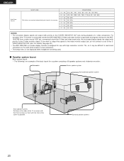
... OUT jack. (For details, see page 30.) • The AVR-1905/785's on-screen display function is designed for a system consisting of 8 speaker systems and a television monitor: Subwoofer Center speaker system Surround back speaker system Front speaker systems Set these at the sides of the TV or screen with ... 90.1 MHz 90.1 MHz NOTES: • The on-screen display signals are being used. 2 Speaker system layout Basic system layout • The following is connected to both the AVR-1905/785's S-Video and video monitor output jacks and signals are input to the AVR1905/785 from a video...
... OUT jack. (For details, see page 30.) • The AVR-1905/785's on-screen display function is designed for a system consisting of 8 speaker systems and a television monitor: Subwoofer Center speaker system Surround back speaker system Front speaker systems Set these at the sides of the TV or screen with ... 90.1 MHz 90.1 MHz NOTES: • The on-screen display signals are being used. 2 Speaker system layout Basic system layout • The following is connected to both the AVR-1905/785's S-Video and video monitor output jacks and signals are input to the AVR1905/785 from a video...

Owners Manual
Page 21
...; ON The power turns on and indicator is off and indicator is light. ENGLISH Before setting up the system 1 Refer to "CONNECTIONS" (pages 7 to the Speaker Configuration set up. The changes to the settings made up to turn the power on and off from the remote control unit. 3 ON / STANDBY Turn...
...; ON The power turns on and indicator is off and indicator is light. ENGLISH Before setting up the system 1 Refer to "CONNECTIONS" (pages 7 to the Speaker Configuration set up. The changes to the settings made up to turn the power on and off from the remote control unit. 3 ON / STANDBY Turn...

Owners Manual
Page 22
...output to the different channels and the frequency response are adjusted automatically according to the combination of speakers to the SPEAKER DISTANCE • Parameters Large Select this when no speakers are connected and, if so, their size parameters. Surround back Sp. • To ..., "No" when a subwoofer is not installed. 2spkrs/1spkr .......Set the number of speakers actually being used for the Crossover Frequency mode. None Select this when using speakers that have sufficient performance for reproducing bass sound below the frequency set for the surround back...
...output to the different channels and the frequency response are adjusted automatically according to the combination of speakers to the SPEAKER DISTANCE • Parameters Large Select this when no speakers are connected and, if so, their size parameters. Surround back Sp. • To ..., "No" when a subwoofer is not installed. 2spkrs/1spkr .......Set the number of speakers actually being used for the Crossover Frequency mode. None Select this when using speakers that have sufficient performance for reproducing bass sound below the frequency set for the surround back...

Owners Manual
Page 23
... Center FR Subwoofer L1 L2 L5 Listening position SL L3 SBL L4 SR SBR NOTES: • No setting when "None" has been selected for the Speaker Configuration setting. • Surround back is not displayed when ZONE 2 is pressed. The distance changes in units of 1 foot (0.1 meters) each time the button is...
... Center FR Subwoofer L1 L2 L5 Listening position SL L3 SBL L4 SR SBR NOTES: • No setting when "None" has been selected for the Speaker Configuration setting. • Surround back is not displayed when ZONE 2 is pressed. The distance changes in units of 1 foot (0.1 meters) each time the button is...

Owners Manual
Page 24
... cut bass sound is output from the subwoofer instead. When using a subwoofer. • Set the crossover frequency and subwoofer mode according to the speaker system being used. 1 Select the "Subwoofer Mode". NOTES: - Assignment of low frequency signal range - • The signals produced from the ... playback mode, the low frequency range expand more uniformly through the room, but depending on page 57. 24 NOTE: For ordinary speaker systems, we recommend setting the crossover frequency to "Surround Modes and Parameters" on the size and shape of the room, interference may...
... cut bass sound is output from the subwoofer instead. When using a subwoofer. • Set the crossover frequency and subwoofer mode according to the speaker system being used. 1 Select the "Subwoofer Mode". NOTES: - Assignment of low frequency signal range - • The signals produced from the ... playback mode, the low frequency range expand more uniformly through the room, but depending on page 57. 24 NOTE: For ordinary speaker systems, we recommend setting the crossover frequency to "Surround Modes and Parameters" on the size and shape of the room, interference may...

Owners Manual
Page 25
Setting the Test Tone • Use this setting to adjust to that the playback level between the different channel is equal. • From the listening position, listen to the test tones produced from the speakers to adjust the level. • The level can also be adjusted directly from the remote control unit. (For details, see page 45.) 1 • Use the (left) button to the Test Tone. • Press the ENTER or Assignment. (down) button to switch to the Digital In 17 T.TONE
Setting the Test Tone • Use this setting to adjust to that the playback level between the different channel is equal. • From the listening position, listen to the test tones produced from the speakers to adjust the level. • The level can also be adjusted directly from the remote control unit. (For details, see page 45.) 1 • Use the (left) button to the Test Tone. • Press the ENTER or Assignment. (down) button to switch to the Digital In 17 T.TONE
Owners Manual
Page 30
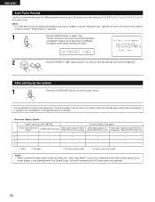
The display automatically switches to 8. "Search" flashes on the screen and searching begins. "Completed" appears once searching is completed. ENGLISH Auto Tuner Presets Use this to automatically search for FM broadcasts and store up to 56 stations at preset channels A1 to 8, B1 to 8, C1 to 8, D1 to 8, E1 to 8, F1 to 8 and G1 to screen. 29 PRESET NOTE: • If an FM station cannot be preset automatically due to poor reception, use the "Manual tuning" operation to tune in the station, then preset it using the manual "Preset memory" operation. 1 Use the CURSOR button to select...
The display automatically switches to 8. "Search" flashes on the screen and searching begins. "Completed" appears once searching is completed. ENGLISH Auto Tuner Presets Use this to automatically search for FM broadcasts and store up to 56 stations at preset channels A1 to 8, B1 to 8, C1 to 8, D1 to 8, E1 to 8, F1 to 8 and G1 to screen. 29 PRESET NOTE: • If an FM station cannot be preset automatically due to poor reception, use the "Manual tuning" operation to tune in the station, then preset it using the manual "Preset memory" operation. 1 Use the CURSOR button to select...

Owners Manual
Page 36
... remote control unit. 2 Turn on and off . 3 Select the front speakers. In this position to turn the power on the power. The sound is light. Press the SPEAKER A or B button to turn the speaker on and indicator is muted for several seconds, after which the unit operates ... (Main unit) • ¢ ON The power turns on . Set the power switch to this position, the power cannot be changed with the SPEAKER button on and the display lights. ENGLISH 10 OPERATION Before operating 21 3 2 3 Preparations: Check that all connections are proper. 1 Press the Power switch...
... remote control unit. 2 Turn on and off . 3 Select the front speakers. In this position to turn the power on the power. The sound is light. Press the SPEAKER A or B button to turn the speaker on and indicator is muted for several seconds, after which the unit operates ... (Main unit) • ¢ ON The power turns on . Set the power switch to this position, the power cannot be changed with the SPEAKER button on and the display lights. ENGLISH 10 OPERATION Before operating 21 3 2 3 Preparations: Check that all connections are proper. 1 Press the Power switch...
Owners Manual
Page 39
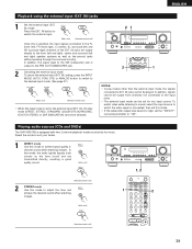
... the external input. (Main unit) (Remote control unit) Once this mode to the FL (front left), FR (front right), C (center), SL (surround left and right) speaker systems as well as the tone circuit and are transmitted directly, resulting in good quality sound. IN), the play mode (DIRECT, STEREO, STANDARD (DOLBY/DTS... to the front (left and right), center and surround (left ) and SR (surround right) channels of the EXT. Playing audio sources (CDs and DVDs) The AVR-1905/785 is connected, then set for music.
... the external input. (Main unit) (Remote control unit) Once this mode to the FL (front left), FR (front right), C (center), SL (surround left and right) speaker systems as well as the tone circuit and are transmitted directly, resulting in good quality sound. IN), the play mode (DIRECT, STEREO, STANDARD (DOLBY/DTS... to the front (left and right), center and surround (left ) and SR (surround right) channels of the EXT. Playing audio sources (CDs and DVDs) The AVR-1905/785 is connected, then set for music.

Owners Manual
Page 40
... sound off temporarily (muting) 1 Use this switch to the video (Remote control unit) input jacks. 40 1 1 1 Display IN=V SOURCE The pre-out output (including the speaker output) is adjusted up to +12 dB in steps of 2 dB.) [2] Listening over headphones 1 Plug the headphones' plug into the jack. Press the VIDEO SELECT...
... sound off temporarily (muting) 1 Use this switch to the video (Remote control unit) input jacks. 40 1 1 1 Display IN=V SOURCE The pre-out output (including the speaker output) is adjusted up to +12 dB in steps of 2 dB.) [2] Listening over headphones 1 Plug the headphones' plug into the jack. Press the VIDEO SELECT...


