Owners Manual
Page 3
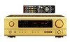
...the connection cords between all other major manufacturers are prestored in the £ OFF or STANDBY state, the apparatus is still connected on Check once again that the following parts are... REAR OF THE CABINET FOR FUTURE REFERENCE" 2 INTRODUCTION Thank you for DENON remote controllable AV components as well as the range of PRE OUT jack, HEADPHONE jack...into five channels (front left/right, center and surround left/right). AUX terminal The AVR-1603's front panel is a new format for explanation purposes. • Before turning the... codes for choosing the DENON A/V Surround receiver.
...the connection cords between all other major manufacturers are prestored in the £ OFF or STANDBY state, the apparatus is still connected on Check once again that the following parts are... REAR OF THE CABINET FOR FUTURE REFERENCE" 2 INTRODUCTION Thank you for DENON remote controllable AV components as well as the range of PRE OUT jack, HEADPHONE jack...into five channels (front left/right, center and surround left/right). AUX terminal The AVR-1603's front panel is a new format for explanation purposes. • Before turning the... codes for choosing the DENON A/V Surround receiver.
Owners Manual
Page 4
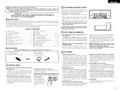
... 16, 17) @6 SIGNAL indicators 16) @7 INPUT mode indicators 16) @8 Remote control sensor (REMOTE SENSOR) ....(9) @9 Power operation indicator (ON/STANDBY) #0 INPUT SELECTOR knob .......(16, 18, 19, 24 ~ 26) System buttons 13, 14) SYSTEM SETUP/ SETUP button 9, 12, 14) ... button 9, 14, 18) RETURN button 14) SPEAKER select button ........(15) DIMMER button 17) NOTE: • The shaded buttons do not function with the AVR-1603. (Nothing happens when they are pressed.) LED (indicator 13, 15) Remote control signal transmitter 9) SURROUND button 16, 18, 19, 21) POWER buttons 13...
... 16, 17) @6 SIGNAL indicators 16) @7 INPUT mode indicators 16) @8 Remote control sensor (REMOTE SENSOR) ....(9) @9 Power operation indicator (ON/STANDBY) #0 INPUT SELECTOR knob .......(16, 18, 19, 24 ~ 26) System buttons 13, 14) SYSTEM SETUP/ SETUP button 9, 12, 14) ... button 9, 14, 18) RETURN button 14) SPEAKER select button ........(15) DIMMER button 17) NOTE: • The shaded buttons do not function with the AVR-1603. (Nothing happens when they are pressed.) LED (indicator 13, 15) Remote control signal transmitter 9) SURROUND button 16, 18, 19, 21) POWER buttons 13...
Owners Manual
Page 5
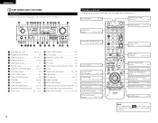
... pin plug cords together with the POWER switch on the main unit, and when the power is switched between on and standby from these at standby. Connections for audio equipment. NOTE: Only use . Never use them for recording: Connect the tape deck's recording input ...AVR-1603's OPTICAL OUT terminal is an optical digital output terminal for digital recording. Do not use them near a power transformer will result in analog, also connect the analog signals of the player to setup the speakers and connecting the components. ENGLISH 6 READ THIS FIRST This A / V surround Receiver...
... pin plug cords together with the POWER switch on the main unit, and when the power is switched between on and standby from these at standby. Connections for audio equipment. NOTE: Only use . Never use them for recording: Connect the tape deck's recording input ...AVR-1603's OPTICAL OUT terminal is an optical digital output terminal for digital recording. Do not use them near a power transformer will result in analog, also connect the analog signals of the player to setup the speakers and connecting the components. ENGLISH 6 READ THIS FIRST This A / V surround Receiver...
Owners Manual
Page 14
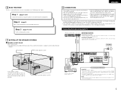
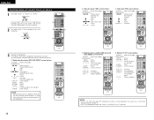
... that component. 14 2. NOTES: • For this remote control unit. 1. ENGLISH Operating component stored in the same way as for Denon audio components (page 13). • The TV can be operated in the preset memory 1 Set mode switch 1 to "AUDIO" or... 3 3 Operate the component. • For details, refer to the component's operating instructions. Digital broadcast satellite (DBS) tuner and cable (CABLE) system buttons POWER : Power on /standby (ON/SOURCE) MENU : Menu RETURN : Return D, H, F, G : Cursor up, down, left and right ENTER : Enter CHANNEL : Switch channels +, - 0~9, +10 : ...
... that component. 14 2. NOTES: • For this remote control unit. 1. ENGLISH Operating component stored in the same way as for Denon audio components (page 13). • The TV can be operated in the preset memory 1 Set mode switch 1 to "AUDIO" or... 3 3 Operate the component. • For details, refer to the component's operating instructions. Digital broadcast satellite (DBS) tuner and cable (CABLE) system buttons POWER : Power on /standby (ON/SOURCE) MENU : Menu RETURN : Return D, H, F, G : Cursor up, down, left and right ENTER : Enter CHANNEL : Switch channels +, - 0~9, +10 : ...
Owners Manual
Page 15
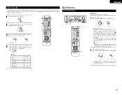
... that prevents noise when the power switch is turned on and off from the time the power operation switch is set to the "¢ ON/STANDBY" position until sound is output. Press the SPEAKER A or B button turn the power on and off from the included remote control unit. • £ OFF... component to the built-in the DBS/CABLE or TV mode. Press the power operation switch (button). (Main unit) (Remote control unit) • ¢ ON/STANDBY The power turns on the CD, TAPE, CDR/MD, DVD/VDP or VCR components when in muting circuit that all connections are required from the...
... that prevents noise when the power switch is turned on and off from the time the power operation switch is set to the "¢ ON/STANDBY" position until sound is output. Press the SPEAKER A or B button turn the power on and off from the included remote control unit. • £ OFF... component to the built-in the DBS/CABLE or TV mode. Press the power operation switch (button). (Main unit) (Remote control unit) • ¢ ON/STANDBY The power turns on the CD, TAPE, CDR/MD, DVD/VDP or VCR components when in muting circuit that all connections are required from the...
Owners Manual
Page 25
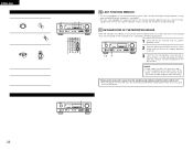
Turning on the main unit's power from the standby mode without using the main unit's power operation switch. 2 Hold the following procedure. 1 Switch off . • The unit is flashing with a back-up memory. ENGLISH ...
Turning on the main unit's power from the standby mode without using the main unit's power operation switch. 2 Hold the following procedure. 1 Switch off . • The unit is flashing with a back-up memory. ENGLISH ...

