Owner's Manual
Page 3
...-Board Components 13 Removing the Computer Cover 15 Procedure 15 Replacing the Computer Cover 16 Procedure 16 Postrequisites 16 Removing the Memory Module(s 17 Prerequisites 17 Procedure 17 Replacing the Memory Module(s 18 Procedure 18 Postrequisites 20 Removing the Front Bezel 21 Prerequisites 21 Procedure 22 Replacing the Front Bezel 23 Procedure...
...-Board Components 13 Removing the Computer Cover 15 Procedure 15 Replacing the Computer Cover 16 Procedure 16 Postrequisites 16 Removing the Memory Module(s 17 Prerequisites 17 Procedure 17 Replacing the Memory Module(s 18 Procedure 18 Postrequisites 20 Removing the Front Bezel 21 Prerequisites 21 Procedure 22 Replacing the Front Bezel 23 Procedure...
Owner's Manual
Page 13
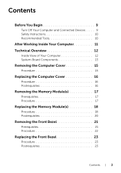
System-Board Components 12 3 4 5 6 78 9 29 28 27 10 26 11 12 25 13 14 24 23 22 21 20 19 18 17 16 15 1 chassis fan connector (SYS_FAN 1) 3 processor socket 5 memory module connector (DIMM3) 7 memory module connector (DIMM4) 9 main power connector (PWR1) 2 power connector (PWRCONN1) 4 processor fan connector (CPU_FAN) 6 memory module connector (DIMM1) 8 memory module connector (DIMM2) 10 CMOS reset jumper (RTCRST) Technical Overview | 13
System-Board Components 12 3 4 5 6 78 9 29 28 27 10 26 11 12 25 13 14 24 23 22 21 20 19 18 17 16 15 1 chassis fan connector (SYS_FAN 1) 3 processor socket 5 memory module connector (DIMM3) 7 memory module connector (DIMM4) 9 main power connector (PWR1) 2 power connector (PWRCONN1) 4 processor fan connector (CPU_FAN) 6 memory module connector (DIMM1) 8 memory module connector (DIMM2) 10 CMOS reset jumper (RTCRST) Technical Overview | 13
Owner's Manual
Page 17
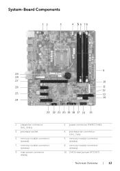
... in "Before You Begin" on page 9. Allow the memory module(s) to remove it from the connector. 2 Grasp the memory module and pull it upward. 3 2 1 1 memory-module connector 3 securing clips (2) 2 memory module Removing the Memory Module(s) | 17 For additional safety best practices information, ... during normal operation. NOTE: If the memory module is difficult to remove, gently ease the memory module back and forth to cool before touching them. 1 Press out the securing clip at dell.com/regulatory_compliance. Removing the Memory Module(s) WARNING: Before working inside your...
... in "Before You Begin" on page 9. Allow the memory module(s) to remove it from the connector. 2 Grasp the memory module and pull it upward. 3 2 1 1 memory-module connector 3 securing clips (2) 2 memory module Removing the Memory Module(s) | 17 For additional safety best practices information, ... during normal operation. NOTE: If the memory module is difficult to remove, gently ease the memory module back and forth to cool before touching them. 1 Press out the securing clip at dell.com/regulatory_compliance. Removing the Memory Module(s) WARNING: Before working inside your...
Owner's Manual
Page 18
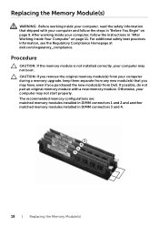
... computer, read the safety information that you remove the original memory module(s) from your computer during a memory upgrade, keep them separate from Dell. After working inside your computer, follow the steps in DIMM connectors 3 and 4. 18 | Replacing the Memory Module(s) The recommended memory configurations are: matched memory modules installed in DIMM connectors 1 and 2 and another matched...
... computer, read the safety information that you remove the original memory module(s) from your computer during a memory upgrade, keep them separate from Dell. After working inside your computer, follow the steps in DIMM connectors 3 and 4. 18 | Replacing the Memory Module(s) The recommended memory configurations are: matched memory modules installed in DIMM connectors 1 and 2 and another matched...
Owner's Manual
Page 19
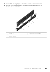
1 Press out the securing clip at each end of the memory-module connector. 2 Align the notch on the bottom of the memory module with the tab on the memory-module connector. 1 cutouts (2) 3 tab 5 memory module 5 4 3 2 1 2 memory-module connector 4 notch Replacing the Memory Module(s) | 19
1 Press out the securing clip at each end of the memory-module connector. 2 Align the notch on the bottom of the memory module with the tab on the memory-module connector. 1 cutouts (2) 3 tab 5 memory module 5 4 3 2 1 2 memory-module connector 4 notch Replacing the Memory Module(s) | 19
Owner's Manual
Page 20
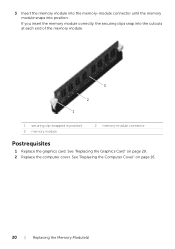
See "Replacing the Computer Cover" on page 29. 2 Replace the computer cover. 3 Insert the memory module into the memory-module connector until the memory module snaps into the cutouts at each end of the memory module. 3 2 1 1 securing clip (snapped in position) 3 memory module 2 memory-module connector Postrequisites 1 Replace the graphics card. See "Replacing the Graphics Card" on page 16. 20 | Replacing the Memory Module(s) If you insert the memory module correctly, the securing clips snap into position.
See "Replacing the Computer Cover" on page 29. 2 Replace the computer cover. 3 Insert the memory module into the memory-module connector until the memory module snaps into the cutouts at each end of the memory module. 3 2 1 1 securing clip (snapped in position) 3 memory module 2 memory-module connector Postrequisites 1 Replace the graphics card. See "Replacing the Graphics Card" on page 16. 20 | Replacing the Memory Module(s) If you insert the memory module correctly, the securing clips snap into position.
Owner's Manual
Page 73
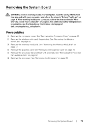
Prerequisites 1 Remove the computer cover. See "Removing the Memory Module(s)" on page 15. 2 Remove the wireless mini-card, if applicable. Removing the System Board WARNING: Before working inside your computer, read the safety information .... See "Removing the Processor" on page 62. 6 Remove the processor. Removing the System Board | 73 See "Removing the Graphics Card" on page 30. 3 Remove the memory module(s). See "Removing the Wireless Mini-Card" on page 26. 5 Remove the processor fan and heat-sink assembly. For additional safety best practices information, see...
Prerequisites 1 Remove the computer cover. See "Removing the Memory Module(s)" on page 15. 2 Remove the wireless mini-card, if applicable. Removing the System Board WARNING: Before working inside your computer, read the safety information .... See "Removing the Processor" on page 62. 6 Remove the processor. Removing the System Board | 73 See "Removing the Graphics Card" on page 30. 3 Remove the memory module(s). See "Removing the Wireless Mini-Card" on page 26. 5 Remove the processor fan and heat-sink assembly. For additional safety best practices information, see...
Owner's Manual
Page 75
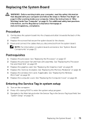
...Replace the graphics card. See "Replacing the Computer Cover" on page 18. 5 Replace the wireless mini-card, if applicable. See "Replacing the Memory Module(s)" on page 16. Replacing the System Board WARNING: Before working inside your computer, read the safety information that shipped with your computer, ... See "Replacing the Graphics Card" on page 13. For additional safety best practices information, see the Regulatory Compliance Homepage at dell.com/regulatory_compliance. NOTE: For information on system board connectors, See "System-Board Components" on page 29. 4 Replace the...
...Replace the graphics card. See "Replacing the Computer Cover" on page 18. 5 Replace the wireless mini-card, if applicable. See "Replacing the Memory Module(s)" on page 16. Replacing the System Board WARNING: Before working inside your computer, read the safety information that shipped with your computer, ... See "Replacing the Graphics Card" on page 13. For additional safety best practices information, see the Regulatory Compliance Homepage at dell.com/regulatory_compliance. NOTE: For information on system board connectors, See "System-Board Components" on page 29. 4 Replace the...
Owner's Manual
Page 78
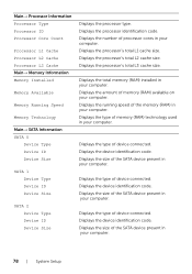
...computer. Displays the size of the SATA device present in your computer. Displays the type of the memory (RAM) in your computer. Displays the processor's total L3 cache size. Displays the device identification code. Displays the running speed ... Processor Information Processor Type Processor ID Processor Core Count Processor L1 Cache Processor L2 Cache Processor L3 Cache Main→ Memory Information Memory Installed Memory Available Memory Running Speed Memory Technology Main→ SATA Information SATA 0 Device Type Device ID Device Size SATA 1 Device Type Device ID Device ...
...computer. Displays the size of the SATA device present in your computer. Displays the type of the memory (RAM) in your computer. Displays the processor's total L3 cache size. Displays the device identification code. Displays the running speed ... Processor Information Processor Type Processor ID Processor Core Count Processor L1 Cache Processor L2 Cache Processor L3 Cache Main→ Memory Information Memory Installed Memory Available Memory Running Speed Memory Technology Main→ SATA Information SATA 0 Device Type Device ID Device Size SATA 1 Device Type Device ID Device ...
Owner's Manual
Page 82
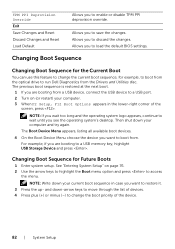
... a USB port. 2 Turn on page 76. 2 Use the arrow keys to highlight the Boot menu option and press to run Dell Diagnostics from a USB device, connect the USB device to a USB memory key, highlight USB Storage Device and press . Allows you to change the current boot sequence, for Future Boots 1 Enter system...
... a USB port. 2 Turn on page 76. 2 Use the arrow keys to highlight the Boot menu option and press to run Dell Diagnostics from a USB device, connect the USB device to a USB memory key, highlight USB Storage Device and press . Allows you to change the current boot sequence, for Future Boots 1 Enter system...


