Owner's Manual
Page 3
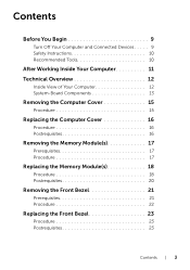
... Computer and Connected Devices . . . . . 9 Safety Instructions 10 Recommended Tools 10 After Working Inside Your Computer 11 Technical Overview 12 Inside View of Your Computer 12 System-Board Components 13 Removing the Computer Cover 15 Procedure 15 Replacing the Computer Cover 16 Procedure 16 Postrequisites 16 Removing the Memory Module(s 17 Prerequisites 17 Procedure 17 Replacing the Memory Module(s 18 Procedure 18 Postrequisites 20 Removing the Front...
... Computer and Connected Devices . . . . . 9 Safety Instructions 10 Recommended Tools 10 After Working Inside Your Computer 11 Technical Overview 12 Inside View of Your Computer 12 System-Board Components 13 Removing the Computer Cover 15 Procedure 15 Replacing the Computer Cover 16 Procedure 16 Postrequisites 16 Removing the Memory Module(s 17 Prerequisites 17 Procedure 17 Replacing the Memory Module(s 18 Procedure 18 Postrequisites 20 Removing the Front...
Owner's Manual
Page 8
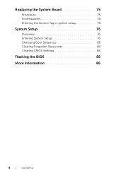
Replacing the System Board 75 Procedure 75 Postrequisites 75 Entering the Service Tag in system setup 75 System Setup 76 Overview 76 Entering System Setup 76 Changing Boot Sequence 82 Clearing Forgotten Passwords 83 Clearing CMOS Settings 84 Flashing the BIOS 85 More Information 86 8 | Contents
Replacing the System Board 75 Procedure 75 Postrequisites 75 Entering the Service Tag in system setup 75 System Setup 76 Overview 76 Entering System Setup 76 Changing Boot Sequence 82 Clearing Forgotten Passwords 83 Clearing CMOS Settings 84 Flashing the BIOS 85 More Information 86 8 | Contents
Owner's Manual
Page 10
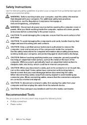
... covers, panels, and screws before connecting to protect your computer from the network device. CAUTION: Only a certified service technician is flat and clean. When disconnecting cables, keep them by touching an unpainted metal surface, such as the metal at dell.com/regulatory_compliance. See the safety instructions for complete information about safety precautions, working inside the computer, replace all power sources before disconnecting the cable...
... covers, panels, and screws before connecting to protect your computer from the network device. CAUTION: Only a certified service technician is flat and clean. When disconnecting cables, keep them by touching an unpainted metal surface, such as the metal at dell.com/regulatory_compliance. See the safety instructions for complete information about safety precautions, working inside the computer, replace all power sources before disconnecting the cable...

Owner's Manual
Page 11
... stray screws remain inside your computer. • Place the computer in an upright position. • Connect any external devices, cables, cards, and any other part(s) you complete the replacement procedures, ensure the following: • Replace all screws and ensure that no stray screws remain inside the computer. After Working Inside Your Computer After you removed before working on your computer. •...
... stray screws remain inside your computer. • Place the computer in an upright position. • Connect any external devices, cables, cards, and any other part(s) you complete the replacement procedures, ensure the following: • Replace all screws and ensure that no stray screws remain inside the computer. After Working Inside Your Computer After you removed before working on your computer. •...
Owner's Manual
Page 17
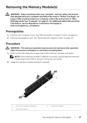
... of the memory-module connector. See "Removing the Computer Cover" on page 26. Allow the memory module(s) to remove it from the connector. 2 Grasp the memory module and pull it upward. 3 2 1 1 memory-module connector 3 securing clips (2) 2 memory module Removing the Memory Module(s) | 17 See "Removing the Graphics Card" on page 15. 2 Remove the graphics card. Procedure WARNING: The memory module(s) may become hot during normal operation. After working inside your computer and follow the instructions in...
... of the memory-module connector. See "Removing the Computer Cover" on page 26. Allow the memory module(s) to remove it from the connector. 2 Grasp the memory module and pull it upward. 3 2 1 1 memory-module connector 3 securing clips (2) 2 memory module Removing the Memory Module(s) | 17 See "Removing the Graphics Card" on page 15. 2 Remove the graphics card. Procedure WARNING: The memory module(s) may become hot during normal operation. After working inside your computer and follow the instructions in...
Owner's Manual
Page 18
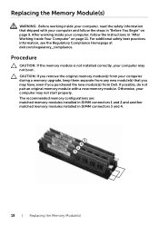
... original memory module(s) from your computer during a memory upgrade, keep them separate from any new module(s) that shipped with a new memory module. If possible, do not pair an original memory module with your computer and follow the instructions in DIMM connectors 3 and 4. 18 | Replacing the Memory Module(s) Replacing the Memory Module(s) WARNING: Before working inside your computer, read the safety information that you may not boot. The recommended memory configurations are: matched memory modules installed...
... original memory module(s) from your computer during a memory upgrade, keep them separate from any new module(s) that shipped with a new memory module. If possible, do not pair an original memory module with your computer and follow the instructions in DIMM connectors 3 and 4. 18 | Replacing the Memory Module(s) Replacing the Memory Module(s) WARNING: Before working inside your computer, read the safety information that you may not boot. The recommended memory configurations are: matched memory modules installed...
Owner's Manual
Page 37
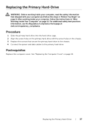
... 9. Procedure 1 Slide the primary hard-drive into the hard-drive cage. 2 Align the screw holes on the primary hard-drive with your computer, read the safety information that shipped with the screw holes on the chassis. 3 Replace the screws that secure the primary hard-drive to the chassis. 4 Connect the power and data cables to the primary hard-drive. After working inside your computer, follow...
... 9. Procedure 1 Slide the primary hard-drive into the hard-drive cage. 2 Align the screw holes on the primary hard-drive with your computer, read the safety information that shipped with the screw holes on the chassis. 3 Replace the screws that secure the primary hard-drive to the chassis. 4 Connect the power and data cables to the primary hard-drive. After working inside your computer, follow...

Owner's Manual
Page 40
... not touch the metal housing of the hard drive. Prerequisites 1 Remove the computer cover. Procedure 1 Remove the screws that shipped with your computer, read the safety information that secure the secondary hard-drive to the hard-drive cage. 2 Slide the secondary hard-drive out from the computer when the drive is hot, do not remove the hard drive while the computer is on or in "After Working Inside...
... not touch the metal housing of the hard drive. Prerequisites 1 Remove the computer cover. Procedure 1 Remove the screws that shipped with your computer, read the safety information that secure the secondary hard-drive to the hard-drive cage. 2 Slide the secondary hard-drive out from the computer when the drive is hot, do not remove the hard drive while the computer is on or in "After Working Inside...

Owner's Manual
Page 41
... at dell.com/regulatory_compliance. Postrequisites 1 Replace the hard-drive cage. See "Replacing the Computer Cover" on page 9. See "Replacing the Primary Hard-Drive" on page 39. 2 Replace the primary hard-drive. Replacing the Secondary Hard-Drive (optional) | 41 Procedure 1 Slide the secondary hard-drive into the hard-drive cage. 2 Replace the screws that shipped with your computer, follow the steps in "After Working Inside Your Computer" on page 11. See "Replacing the Hard-Drive Cage...
... at dell.com/regulatory_compliance. Postrequisites 1 Replace the hard-drive cage. See "Replacing the Computer Cover" on page 9. See "Replacing the Primary Hard-Drive" on page 39. 2 Replace the primary hard-drive. Replacing the Secondary Hard-Drive (optional) | 41 Procedure 1 Slide the secondary hard-drive into the hard-drive cage. 2 Replace the screws that shipped with your computer, follow the steps in "After Working Inside Your Computer" on page 11. See "Replacing the Hard-Drive Cage...

Owner's Manual
Page 44
See "Replacing the Computer Cover" on page 23. 2 Replace the computer cover. See "Replacing the Front Bezel" on page 16. 44 | Installing a third Hard-Drive (optional) 4 Replace the screws that secure the third hard-drive to the chassis. 5 Connect the power and data cables to the third hard-drive. 1 2 3 1 power cable 3 screws (2) 2 data cable Postrequisites 1 Replace the front bezel.
See "Replacing the Computer Cover" on page 23. 2 Replace the computer cover. See "Replacing the Front Bezel" on page 16. 44 | Installing a third Hard-Drive (optional) 4 Replace the screws that secure the third hard-drive to the chassis. 5 Connect the power and data cables to the third hard-drive. 1 2 3 1 power cable 3 screws (2) 2 data cable Postrequisites 1 Replace the front bezel.

Owner's Manual
Page 69
CAUTION: Removing the coin-cell battery resets the BIOS settings to default. It is recommended that shipped with your computer and follow the instructions in "Before You Begin" on page 15. Prerequisites Remove the computer cover. See "System-Board Components" on the system board. After working inside your computer, follow the steps in "After Working Inside Your Computer" on page 11. Procedure 1 Locate the battery socket...
CAUTION: Removing the coin-cell battery resets the BIOS settings to default. It is recommended that shipped with your computer and follow the instructions in "Before You Begin" on page 15. Prerequisites Remove the computer cover. See "System-Board Components" on the system board. After working inside your computer, follow the steps in "After Working Inside Your Computer" on page 11. Procedure 1 Locate the battery socket...

Owner's Manual
Page 71
... the instructions in "Before You Begin" on page 9. For additional safety best practices information, see the Regulatory Compliance Homepage at dell.com/regulatory_compliance. See "System-Board Components" on page 15. Prerequisites Remove the computer cover. Procedure 1 Disconnect the DC power cables from the chassis 3 2 1 1 screws (4) 3 power-supply clamps (2) 2 power supply Removing the Power-Supply Unit | 71 Removing the Power-Supply Unit WARNING: Before working...
... the instructions in "Before You Begin" on page 9. For additional safety best practices information, see the Regulatory Compliance Homepage at dell.com/regulatory_compliance. See "System-Board Components" on page 15. Prerequisites Remove the computer cover. Procedure 1 Disconnect the DC power cables from the chassis 3 2 1 1 screws (4) 3 power-supply clamps (2) 2 power supply Removing the Power-Supply Unit | 71 Removing the Power-Supply Unit WARNING: Before working...
Owner's Manual
Page 73
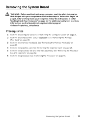
... Computer" on page 11. See "Removing the Wireless Mini-Card" on page 15. 2 Remove the wireless mini-card, if applicable. See "Removing the Graphics Card" on page 62. 6 Remove the processor. Removing the System Board | 73 After working inside your computer and follow the instructions in "Before You Begin" on page 9. Prerequisites 1 Remove the computer cover. See "Removing the Processor Fan and Heat-Sink" on page 26...
... Computer" on page 11. See "Removing the Wireless Mini-Card" on page 15. 2 Remove the wireless mini-card, if applicable. See "Removing the Graphics Card" on page 62. 6 Remove the processor. Removing the System Board | 73 After working inside your computer and follow the instructions in "Before You Begin" on page 9. Prerequisites 1 Remove the computer cover. See "Removing the Processor Fan and Heat-Sink" on page 26...
Owner's Manual
Page 75
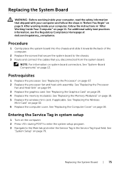
... follow the instructions in "After Working Inside Your Computer" on page 11. See "Replacing the Wireless Mini-Card" on the computer. 2 Press during POST to enter the system setup program. 3 Navigate to the chassis. 3 Route and connect the cables that shipped with your computer, follow the steps in "Before You Begin" on page 9. Entering the Service Tag in system setup 1 Turn on page...
... follow the instructions in "After Working Inside Your Computer" on page 11. See "Replacing the Wireless Mini-Card" on the computer. 2 Press during POST to enter the system setup program. 3 Navigate to the chassis. 3 Route and connect the cables that shipped with your computer, follow the steps in "Before You Begin" on page 9. Entering the Service Tag in system setup 1 Turn on page...
Owner's Manual
Page 76
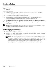
Then, turn off your computer work incorrectly. NOTE: The F2 prompt indicates that you write down the system setup screen information for the F2 prompt to appear and then press immediately. NOTE: Before you change a user-selectable option, such as the user password, type of hard drive installed, enabling or disabling base devices, and so on (or restart) your computer. 2 During POST, when the DELL logo is displayed, watch for...
Then, turn off your computer work incorrectly. NOTE: The F2 prompt indicates that you write down the system setup screen information for the F2 prompt to appear and then press immediately. NOTE: Before you change a user-selectable option, such as the user password, type of hard drive installed, enabling or disabling base devices, and so on (or restart) your computer. 2 During POST, when the DELL logo is displayed, watch for...

Owner's Manual
Page 77
... Service Tag is divided into three areas: the setup item, active help screen, and key functions. Allows you can view information about your computer and make that define the configuration of your computer. Information on your computer and installed devices, the items listed in this field you to your current settings. Scroll up - NOTE: Not all settings listed in the Setup Item. Main→ System Information BIOS...
... Service Tag is divided into three areas: the setup item, active help screen, and key functions. Allows you can view information about your computer and make that define the configuration of your computer. Information on your computer and installed devices, the items listed in this field you to your current settings. Scroll up - NOTE: Not all settings listed in the Setup Item. Main→ System Information BIOS...

Owner's Manual
Page 79
... the processor load. CPU XD Support If enabled, allows your computer. Intel(R) Turbo Boost Technology If enabled, allows your computer. System Setup | 79 Displays the type of device connected. Intel(R) Virtualization Technology If enabled, a Virtual Machine Monitor (VMM) can access your computer to hinder software that exploits buffer overflows. NOTE: Windows 8 enables this feature even if this feature is set to enable or disable the USB ports at the back...
... the processor load. CPU XD Support If enabled, allows your computer. Intel(R) Turbo Boost Technology If enabled, allows your computer. System Setup | 79 Displays the type of device connected. Intel(R) Virtualization Technology If enabled, a Virtual Machine Monitor (VMM) can access your computer to hinder software that exploits buffer overflows. NOTE: Windows 8 enables this feature even if this feature is set to enable or disable the USB ports at the back...
Owner's Manual
Page 80
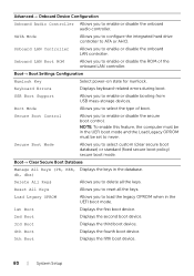
... keys. USB Boot Support Allows you to enable or disable the onboard LAN controller. Onboard LAN Controller Allows you to enable or disable booting from USB mass-storage devices. Secure Boot Mode Allows you to enable or disable the onboard audio controller. Advanced→ Onboard Device Configuration Onboard Audio Controller Allows you to select custom (clear secure boot database) or standard (fixed secure boot policy) secure boot mode. Boot→ Boot Settings Configuration Numlock Key Select power-on state for numlock. Keyboard Errors Displays keyboard-related errors...
... keys. USB Boot Support Allows you to enable or disable the onboard LAN controller. Onboard LAN Controller Allows you to enable or disable booting from USB mass-storage devices. Secure Boot Mode Allows you to enable or disable the onboard audio controller. Advanced→ Onboard Device Configuration Onboard Audio Controller Allows you to select custom (clear secure boot database) or standard (fixed secure boot policy) secure boot mode. Boot→ Boot Settings Configuration Numlock Key Select power-on state for numlock. Keyboard Errors Displays keyboard-related errors...
Owner's Manual
Page 81
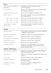
... set a supervisor password. If enabled, clears the TPM module settings. Security Unlock Setup Supervisor Password User Password Set Supervisor Password User Access Level Set User Password Password Check Security→ TPM Security TPM Security Support TPM Status Clear TPM TPM ACPI Support TPM PPI Provision Override If the supervisor password is restored. Displays the status of the supervisor password. Allows you to configure the DeepSx mode. Allows you to enable or disable TPM PPI provision override. Allows you to set the user-access...
... set a supervisor password. If enabled, clears the TPM module settings. Security Unlock Setup Supervisor Password User Password Set Supervisor Password User Access Level Set User Password Password Check Security→ TPM Security TPM Security Support TPM Status Clear TPM TPM ACPI Support TPM PPI Provision Override If the supervisor password is restored. Displays the status of the supervisor password. Allows you to configure the DeepSx mode. Allows you to enable or disable TPM PPI provision override. Allows you to set the user-access...
Owner's Manual
Page 82
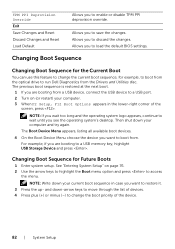
... optical drive to change the boot priority of the screen, press . Changing Boot Sequence Changing Boot Sequence for the Current Boot You can use this feature to run Dell Diagnostics from the Drivers and Utilities disc. and down your computer. 3 When F2 Setup, F12 Boot Options appears in case you want to access the menu. Then shut down -arrow keys to move through the list of devices. 4 Press plus (+) or minus (-) to a USB port. 2 Turn...
... optical drive to change the boot priority of the screen, press . Changing Boot Sequence Changing Boot Sequence for the Current Boot You can use this feature to run Dell Diagnostics from the Drivers and Utilities disc. and down your computer. 3 When F2 Setup, F12 Boot Options appears in case you want to access the menu. Then shut down -arrow keys to move through the list of devices. 4 Press plus (+) or minus (-) to a USB port. 2 Turn...


