
Owner's Manual
Page 3
... Recommended Tools...6 Turning Off Your Computer...6 After Working Inside Your Computer...6 2 Removing The Cover...7 Installing The Cover...8 3 Removing The Memory...9 Installing The Memory...9 4 Removing The Expansion Card 11 Installing The Expansion Card...12 5 Removing The Optical Disk Drive 13 Installing The Optical Disk Drive......14 6 Removing The Hard Disk Drive 15 Installing The Hard Disk Drive...16 7 Removing The Memory Card Reader 19 Installing The Memory Card Reader...20 8 Removing The Rear System Fan 21 Installing The Rear System Fan...22 9 Removing The Coin...
... Recommended Tools...6 Turning Off Your Computer...6 After Working Inside Your Computer...6 2 Removing The Cover...7 Installing The Cover...8 3 Removing The Memory...9 Installing The Memory...9 4 Removing The Expansion Card 11 Installing The Expansion Card...12 5 Removing The Optical Disk Drive 13 Installing The Optical Disk Drive......14 6 Removing The Hard Disk Drive 15 Installing The Hard Disk Drive...16 7 Removing The Memory Card Reader 19 Installing The Memory Card Reader...20 8 Removing The Rear System Fan 21 Installing The Rear System Fan...22 9 Removing The Coin...
Owner's Manual
Page 9
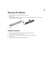
Follow the procedures in Before Working Inside Your Computer. 2. 3 Removing The Memory 1. Insert the memory module into the memory socket. 3. Follow the procedures in After Working Inside Your Computer. 9 Remove the cover. 3. Align the notch on the memory module until the securing clips secure the memory in the system-board connector. 2. Install the cover. 5. Press down...
Follow the procedures in Before Working Inside Your Computer. 2. 3 Removing The Memory 1. Insert the memory module into the memory socket. 3. Follow the procedures in After Working Inside Your Computer. 9 Remove the cover. 3. Align the notch on the memory module until the securing clips secure the memory in the system-board connector. 2. Install the cover. 5. Press down...

Owner's Manual
Page 19
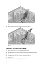
Remove the cover. 3. Unroute the memory card reader cable from the system board. Disconnect the memory card cable from the retention clip. Figure 15. 4. Figure 16. 5. 7 Removing The Memory Card Reader 1. Remove the screws that secure the memory card reader to the drive cage. 19 Follow the procedures in Before Working Inside Your Computer. 2.
Remove the cover. 3. Unroute the memory card reader cable from the system board. Disconnect the memory card cable from the retention clip. Figure 15. 4. Figure 16. 5. 7 Removing The Memory Card Reader 1. Remove the screws that secure the memory card reader to the drive cage. 19 Follow the procedures in Before Working Inside Your Computer. 2.
Owner's Manual
Page 20
Figure 17. 6. Slide the memory card-reader in After Working Inside Your Computer. 20 Replace and tighten the screws that secure the multimedia card-reader to the system board connector. 5. Install the cover. 6. Installing The Memory Card Reader 1. Follow the procedures in through the front of the computer. Slide the multimedia card reader out through the retention clip. 4. Route the memory card reader cable through the front of the computer. 2. Connect the memory card reader cable to the drive cage. 3. Figure 18.
Figure 17. 6. Slide the memory card-reader in After Working Inside Your Computer. 20 Replace and tighten the screws that secure the multimedia card-reader to the system board connector. 5. Install the cover. 6. Installing The Memory Card Reader 1. Follow the procedures in through the front of the computer. Slide the multimedia card reader out through the retention clip. 4. Route the memory card reader cable through the front of the computer. 2. Connect the memory card reader cable to the drive cage. 3. Figure 18.

Owner's Manual
Page 33
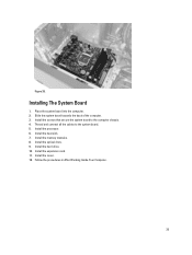
Removing The System Board 1. Remove the cover. 3. Remove the memory card reader. 10. Remove the processor. 7. Remove the hard drive. 8. Remove the optical drive. 9. Remove the expansion card. 5. Disconnect and unthread all the cables on the system board. 13 Figure 32. 11. Remove the memory modules. 4. Remove the screws that secure the system board to the computer chassis. 33 Follow the procedures in Before Working Inside Your Computer. 2. Remove the heat sink. 6.
Removing The System Board 1. Remove the cover. 3. Remove the memory card reader. 10. Remove the processor. 7. Remove the hard drive. 8. Remove the optical drive. 9. Remove the expansion card. 5. Disconnect and unthread all the cables on the system board. 13 Figure 32. 11. Remove the memory modules. 4. Remove the screws that secure the system board to the computer chassis. 33 Follow the procedures in Before Working Inside Your Computer. 2. Remove the heat sink. 6.
Owner's Manual
Page 35
Thread and connect all the cables to the computer chassis. 4. Installing The System Board 1. Install the hard drive. 10. Install the optical drive. 9. Install the expansion card. 11. Slide the system board towards the back of the computer. 3. Install the screws that secure the system board to the system board. 5. Install the heat sink. 7. Install the memory modules. 8. Follow the procedures in After Working Inside Your Computer. 35 Install the processor. 6. Install the cover. 12. Place the system board into the computer. 2. Figure 35.
Thread and connect all the cables to the computer chassis. 4. Installing The System Board 1. Install the hard drive. 10. Install the optical drive. 9. Install the expansion card. 11. Slide the system board towards the back of the computer. 3. Install the screws that secure the system board to the system board. 5. Install the heat sink. 7. Install the memory modules. 8. Follow the procedures in After Working Inside Your Computer. 35 Install the processor. 6. Install the cover. 12. Place the system board into the computer. 2. Figure 35.
Owner's Manual
Page 49
...make up and down your computer. • set or change a user-selectable option such as the user password. • read the current amount of memory or set the type of Options List and contains the System Setup window and field lists features that define the hardware installed on the left... Setup allows you to: • change the system configuration information after you must watch for the F2 prompt to appear. 3. When the blue DELL logo is highlighted, the Options Field Press to return to the Options displays the option's current and List. Once the F2 prompt appears, press ...
...make up and down your computer. • set or change a user-selectable option such as the user password. • read the current amount of memory or set the type of Options List and contains the System Setup window and field lists features that define the hardware installed on the left... Setup allows you to: • change the system configuration information after you must watch for the F2 prompt to appear. 3. When the blue DELL logo is highlighted, the Options Field Press to return to the Options displays the option's current and List. Once the F2 prompt appears, press ...
Owner's Manual
Page 51
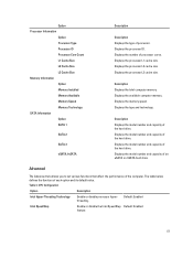
...the performance of an eSATA or mSATA hard drive. Displays the model number and capacity of the computer. Displays the memory speed. Displays the processor L1 cache size. Table 4. Default: Enabled Intel SpeedStep Enable or disable the Intel SpeedStep Default...and capacity of processor. Displays the available computer memory. Option Processor Information Option Processor Type Processor ID Processor Core Count L1 Cache Size L2 Cache Size L3 Cache Size Memory Information Option Memory Installed Memory Available Memory Speed Memory Technology SATA Information Option SATA 1 SATA 2 ...
...the performance of an eSATA or mSATA hard drive. Displays the model number and capacity of the computer. Displays the memory speed. Displays the processor L1 cache size. Table 4. Default: Enabled Intel SpeedStep Enable or disable the Intel SpeedStep Default...and capacity of processor. Displays the available computer memory. Option Processor Information Option Processor Type Processor ID Processor Core Count L1 Cache Size L2 Cache Size L3 Cache Size Memory Information Option Memory Installed Memory Available Memory Speed Memory Technology SATA Information Option SATA 1 SATA 2 ...
Owner's Manual
Page 56
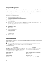
... If so, BIOS will help in resolving this problem, please note this system have failed at booting this checkpoint and contact Dell Technical Support The computer failed to resolve the issue. Code Cause and Troubleshooting Steps 1 BIOS ROM checksum in the following examples,...56 System Messages System Message Description Alert! Diagnostic Beep Codes The computer may display a System Message that was running when the message appeared. No memory detected 3 Chipset Error (North and South Bridge Chipset, DMA/IMR/ Timer Error) , Time-Of-Day Clock test failure , Gate A20 failure ...
... If so, BIOS will help in resolving this problem, please note this system have failed at booting this checkpoint and contact Dell Technical Support The computer failed to resolve the issue. Code Cause and Troubleshooting Steps 1 BIOS ROM checksum in the following examples,...56 System Messages System Message Description Alert! Diagnostic Beep Codes The computer may display a System Message that was running when the message appeared. No memory detected 3 Chipset Error (North and South Bridge Chipset, DMA/IMR/ Timer Error) , Time-Of-Day Clock test failure , Gate A20 failure ...
Owner's Manual
Page 59
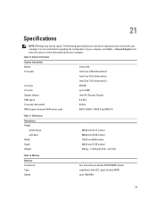
Memory Memory Connectors Type Speed 360.00 mm (14.17 inches) 362.90 mm (14.29 inches) 175.00 mm (6.89 inches) 445.00 mm (17.52 ... computer. 21 Specifications NOTE: Offerings may vary by law to ship with base Width Depth Weight Table 12. Table 10. System Information System Information Model Vostro 470 Processor Intel Core i3 (2nd Generation) Intel Core i5 (3rd Generation) Intel Core i7 (3rd Generation) L2 cache 256 KB L3 cache up to view...
Memory Memory Connectors Type Speed 360.00 mm (14.17 inches) 362.90 mm (14.29 inches) 175.00 mm (6.89 inches) 445.00 mm (17.52 ... computer. 21 Specifications NOTE: Offerings may vary by law to ship with base Width Depth Weight Table 12. Table 10. System Information System Information Model Vostro 470 Processor Intel Core i3 (2nd Generation) Intel Core i5 (3rd Generation) Intel Core i7 (3rd Generation) L2 cache 256 KB L3 cache up to view...
Owner's Manual
Page 60
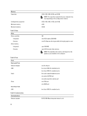
...one audio input/microphone port one VGA port one PCI Express x16, single-width, full length graphics card. Video Video Video controller Integrated Discrete Video memory Integrated Discrete Table 14. Communications Communications Network adapter 60 2 GB, 4 GB, 8 GB, 24 GB, and 32 GB. upto 1024 MB upto 2... GB discrete video memory NOTE: The available video memory will depend on the graphics card installed on the configuration ordered. 2 GB, 4 GB, 8 GB, 12 GB, and 16 GB. 2 GB 32 ...
...one audio input/microphone port one VGA port one PCI Express x16, single-width, full length graphics card. Video Video Video controller Integrated Discrete Video memory Integrated Discrete Table 14. Communications Communications Network adapter 60 2 GB, 4 GB, 8 GB, 24 GB, and 32 GB. upto 1024 MB upto 2... GB discrete video memory NOTE: The available video memory will depend on the graphics card installed on the configuration ordered. 2 GB, 4 GB, 8 GB, 12 GB, and 16 GB. 2 GB 32 ...


