User Manual
Page 1
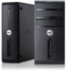
... supply diagnostic light 15. back panel connectors 18. hard-drive activity light 4. USB 2.0 connector 11. power button 14. Regulatory Model: D10M Regulatory Type: D10M002 2011 - 10 Front And Back View Figure 1. front panel door (open ) 8. power connector 17. expansion card slots (4) 19. padlock slot NOTE: The second CD/DVD drive eject button is functional only if a second CD/DVD drive is installed in the computer. Front And Back View 1. drive bay front panel (open ) 13. media card readers (optional) 5. voltage selector switch 16. microphone connector 6. Dell Vostro 470...
... supply diagnostic light 15. back panel connectors 18. hard-drive activity light 4. USB 2.0 connector 11. power button 14. Regulatory Model: D10M Regulatory Type: D10M002 2011 - 10 Front And Back View Figure 1. front panel door (open ) 8. power connector 17. expansion card slots (4) 19. padlock slot NOTE: The second CD/DVD drive eject button is functional only if a second CD/DVD drive is installed in the computer. Front And Back View 1. drive bay front panel (open ) 13. media card readers (optional) 5. voltage selector switch 16. microphone connector 6. Dell Vostro 470...
User Manual
Page 2
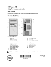
...Panel 1. network adapter connector 3. network activity light 4. HDMI connector 12. Figure 3. center/subwoofer connector 5. line-in this section, read the safety information that shipped with your computer. S/PDIF connector 11. Connect the network cable (optional). Connect the telephone cable (optional). 2 link integrity light 2. USB 2.0 connectors (4) Quick Setup WARNING: Before you did not order them. microphone connector 8. USB 3.0 connectors (2) 14. NOTE: Some cables may not be shipped with your computer. 1. Network Connection 2. rear L/R speaker...
...Panel 1. network adapter connector 3. network activity light 4. HDMI connector 12. Figure 3. center/subwoofer connector 5. line-in this section, read the safety information that shipped with your computer. S/PDIF connector 11. Connect the network cable (optional). Connect the telephone cable (optional). 2 link integrity light 2. USB 2.0 connectors (4) Quick Setup WARNING: Before you did not order them. microphone connector 8. USB 3.0 connectors (2) 14. NOTE: Some cables may not be shipped with your computer. 1. Network Connection 2. rear L/R speaker...

Owner's Manual
Page 3
... Tools...6 Turning Off Your Computer...6 After Working Inside Your Computer...6 2 Removing The Cover...7 Installing The Cover...8 3 Removing The Memory...9 Installing The Memory...9 4 Removing The Expansion Card 11 Installing The Expansion Card...12 5 Removing The Optical Disk Drive 13 Installing The Optical Disk Drive...14 6 Removing The Hard Disk Drive 15 Installing The Hard Disk Drive...16 7 Removing The Memory Card Reader 19 Installing The Memory Card Reader...20 8 Removing The Rear System Fan 21 Installing The Rear System Fan...22 9 Removing The Coin-Cell Battery 23 Installing The...
... Tools...6 Turning Off Your Computer...6 After Working Inside Your Computer...6 2 Removing The Cover...7 Installing The Cover...8 3 Removing The Memory...9 Installing The Memory...9 4 Removing The Expansion Card 11 Installing The Expansion Card...12 5 Removing The Optical Disk Drive 13 Installing The Optical Disk Drive...14 6 Removing The Hard Disk Drive 15 Installing The Hard Disk Drive...16 7 Removing The Memory Card Reader 19 Installing The Memory Card Reader...20 8 Removing The Rear System Fan 21 Installing The Rear System Fan...22 9 Removing The Coin-Cell Battery 23 Installing The...
Owner's Manual
Page 4
... Removing The Power Switch And The Hard Drive Activity LED 41 Installing The Power Switch And The Hard Drive Activity LED 42 17 Removing The Front Audio Module 45 Installing The Front Audio Module...46 18 Removing The Front USB Module 47 Installing The Front USB Module...47 19 System Setup Overview...49 Entering System Setup...49 System Setup Screens...49 System Setup Options...50 Main...50 Advanced...51 Security...53 Boot...53 Exit...53 20 Diagnostic Error Messages 55 Diagnostic Beep Codes...
... Removing The Power Switch And The Hard Drive Activity LED 41 Installing The Power Switch And The Hard Drive Activity LED 42 17 Removing The Front Audio Module 45 Installing The Front Audio Module...46 18 Removing The Front USB Module 47 Installing The Front USB Module...47 19 System Setup Overview...49 Entering System Setup...49 System Setup Screens...49 System Setup Options...50 Main...50 Advanced...51 Security...53 Boot...53 Exit...53 20 Diagnostic Error Messages 55 Diagnostic Beep Codes...
Owner's Manual
Page 5
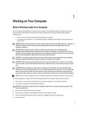
... be replaced or--if purchased separately--installed by a certified service technician. To avoid damaging your computer. Remove the cover. 5 Damage due to servicing that your warranty. Hold a card by its edges or by the online or telephone service and support team. Ensure that is not authorized by Dell is not covered by its pins. For additional safety best practices information, see Turning Off...
... be replaced or--if purchased separately--installed by a certified service technician. To avoid damaging your computer. Remove the cover. 5 Damage due to servicing that your warranty. Hold a card by its edges or by the online or telephone service and support team. Ensure that is not authorized by Dell is not covered by its pins. For additional safety best practices information, see Turning Off...
Owner's Manual
Page 6
.... Replace the cover. Connect your operating system, press and hold the power button for about 4 seconds to their electrical outlets. 4. Turn on your computer. 5. Shut down your computer and all attached devices are turned off after the operating system shutdown process is complete. 2. After Working Inside Your Computer After you complete any replacement procedure, ensure you shut down the operating system: - CAUTION: To connect a network cable, first plug...
.... Replace the cover. Connect your operating system, press and hold the power button for about 4 seconds to their electrical outlets. 4. Turn on your computer. 5. Shut down your computer and all attached devices are turned off after the operating system shutdown process is complete. 2. After Working Inside Your Computer After you complete any replacement procedure, ensure you shut down the operating system: - CAUTION: To connect a network cable, first plug...
Owner's Manual
Page 13
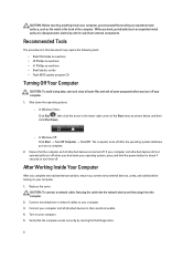
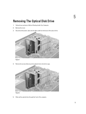
Figure 7. 4. 5 Removing The Optical Disk Drive 1. Remove the screws that secure the optical drive to the drive cage. Slide out the optical drive through the front of the optical drive. Follow the procedures in Before Working Inside Your Computer. 2. Figure 8. 5. Remove the cover. 3. Disconnect the power cable and the data cable from the back of the computer. 13
Figure 7. 4. 5 Removing The Optical Disk Drive 1. Remove the screws that secure the optical drive to the drive cage. Slide out the optical drive through the front of the optical drive. Follow the procedures in Before Working Inside Your Computer. 2. Figure 8. 5. Remove the cover. 3. Disconnect the power cable and the data cable from the back of the computer. 13
Owner's Manual
Page 14
Replace the screws that secure the optical drive to the optical drive. 4. Installing The Optical Disk Drive 1. Install the cover. 5. Slide the optical drive in After Working Inside Your Computer. 14 Connect the power cable and data cable to the drive cage. 3. Figure 9. Follow the procedures in through the front of the computer. 2.
Replace the screws that secure the optical drive to the optical drive. 4. Installing The Optical Disk Drive 1. Install the cover. 5. Slide the optical drive in After Working Inside Your Computer. 14 Connect the power cable and data cable to the drive cage. 3. Figure 9. Follow the procedures in through the front of the computer. 2.
Owner's Manual
Page 16
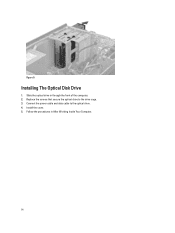
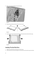
5. Place the hard drive into the slot and tighten the screws that secure the hard drive cage to the drive cage. Figure 14. Installing The Hard Disk Drive 1. Figure 12. 6. Figure 13. 7. Remove the screws that secure the hard drive to remove the hard drive from the hard drive cage. Slide out the hard drive by lifting it in the direction indicated to the drive cage. 2. Pry the hard drive cage in an upward direction. Tighten the screws that secure the hard drive to the chassis. 16
5. Place the hard drive into the slot and tighten the screws that secure the hard drive cage to the drive cage. Figure 14. Installing The Hard Disk Drive 1. Figure 12. 6. Figure 13. 7. Remove the screws that secure the hard drive to remove the hard drive from the hard drive cage. Slide out the hard drive by lifting it in the direction indicated to the drive cage. 2. Pry the hard drive cage in an upward direction. Tighten the screws that secure the hard drive to the chassis. 16

Owner's Manual
Page 45
Remove the front audio module routing cable through the routing clips on the chassis. Remove the front bezel. 4. Disconnect the front audio module cable from the system board. 17 Figure 46. 5. Figure 47. 45 Remove the cover. 3. Removing The Front Audio Module 1. Follow the procedures in Before Working Inside Your Computer. 2.
Remove the front audio module routing cable through the routing clips on the chassis. Remove the front bezel. 4. Disconnect the front audio module cable from the system board. 17 Figure 46. 5. Figure 47. 45 Remove the cover. 3. Removing The Front Audio Module 1. Follow the procedures in Before Working Inside Your Computer. 2.

Owner's Manual
Page 46
Place the front audio module on the front bezel and install the screw that secures the front audio module to its connector on the chassis. 3. Install the front bezel. 5. Install the cover. 6. Connect the front audio module cable to the front bezel and remove the front audio module from the computer. Figure 48. Follow the procedures in After Working Inside Your Computer. 46 Remove the screw that secures it. 2. Route the front audio module cable through the routing clips on the system board. 4. Installing The Front Audio Module 1. 6.
Place the front audio module on the front bezel and install the screw that secures the front audio module to its connector on the chassis. 3. Install the front bezel. 5. Install the cover. 6. Connect the front audio module cable to the front bezel and remove the front audio module from the computer. Figure 48. Follow the procedures in After Working Inside Your Computer. 46 Remove the screw that secures it. 2. Route the front audio module cable through the routing clips on the system board. 4. Installing The Front Audio Module 1. 6.

Owner's Manual
Page 47
.... 2. Removing The Front USB Module 1. Connect the front USB module cable to the front bezel and remove the front USB module from the system board. 18 Figure 49. 5. Remove the front bezel. 4. Follow the procedures in Before Working Inside Your Computer. 2. Disconnect the front USB module data cable and the power cable from the computer. Remove the cover. 3. Figure 50. Install the front bezel. 47 Installing The Front USB Module...
.... 2. Removing The Front USB Module 1. Connect the front USB module cable to the front bezel and remove the front USB module from the system board. 18 Figure 49. 5. Remove the front bezel. 4. Follow the procedures in Before Working Inside Your Computer. 2. Disconnect the front USB module data cable and the power cable from the computer. Remove the cover. 3. Figure 50. Install the front bezel. 47 Installing The Front USB Module...
Owner's Manual
Page 49
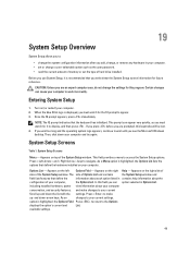
... of hard drive installed. System Setup Screens Menu - Options List - As a Menu option is recommended that define the information about each option listed in contains help information about your computer. Appears on (or restart) your computer. 2. including installed hardware, power view information about the configuration of your computer. • set or change a user-selectable option such as the user password. • read the current amount of memory or set the type of the System Setup window. Entering System Setup 1. Turn...
... of hard drive installed. System Setup Screens Menu - Options List - As a Menu option is recommended that define the information about each option listed in contains help information about your computer. Appears on (or restart) your computer. 2. including installed hardware, power view information about the configuration of your computer. • set or change a user-selectable option such as the user password. • read the current amount of memory or set the type of the System Setup window. Entering System Setup 1. Turn...
Owner's Manual
Page 50
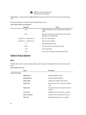
.... 50 or + Change existing item value. < Enter > Select the sub menu or execute command. < F9 > Load setup default. < F10 > Save current configuration and exit System Setup. System Name Displays the computer model number. System Setup Options Main The Main tab lists out the primary hardware features of each option. BIOS Build Date Displays the BIOS build date. System Date Re-sets the date on the computer's internal clock. System Time...
.... 50 or + Change existing item value. < Enter > Select the sub menu or execute command. < F9 > Load setup default. < F10 > Save current configuration and exit System Setup. System Name Displays the computer model number. System Setup Options Main The Main tab lists out the primary hardware features of each option. BIOS Build Date Displays the BIOS build date. System Date Re-sets the date on the computer's internal clock. System Time...
Owner's Manual
Page 51
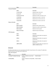
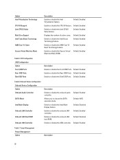
... Size Memory Information Option Memory Installed Memory Available Memory Speed Memory Technology SATA Information Option SATA 1 SATA 2 SATA 3 eSATA /mSATA Description Description Displays the type of the hard drive. Displays the processor L1 cache size. Displays the model number and capacity of processor. Displays the model number and capacity of an eSATA or mSATA hard drive. Displays the model number and capacity of the hard drive. Displays the processor ID. Displays the processor L3 cache size. Displays the available computer memory. Description Displays the model number and...
... Size Memory Information Option Memory Installed Memory Available Memory Speed Memory Technology SATA Information Option SATA 1 SATA 2 SATA 3 eSATA /mSATA Description Description Displays the type of the hard drive. Displays the processor L1 cache size. Displays the model number and capacity of processor. Displays the model number and capacity of an eSATA or mSATA hard drive. Displays the model number and capacity of the hard drive. Displays the processor ID. Displays the processor L3 cache size. Displays the available computer memory. Description Displays the model number and...
Owner's Manual
Page 52
... Machine Mode (SVM). Default: Enabled Enable or disable the Rear USB Ports. Onboard Device Configuration Onboard Device Configuration Option Onboard Audio Controller SATA Mode Intel Multi-Display Onboard LAN Controller Onboard LAN Boot ROM Onboard 1394 Controller Description Enable or disable the onboard audio controller. Enable or disable the Intel MultiDisplay feature. Enable or disable the USB controller. Default: Enabled Enable or disable the Intel Boost Technology feature. Enable or disable the onboard LAN controller. Option Intel Virtualization Technology CPU XD Support...
... Machine Mode (SVM). Default: Enabled Enable or disable the Rear USB Ports. Onboard Device Configuration Onboard Device Configuration Option Onboard Audio Controller SATA Mode Intel Multi-Display Onboard LAN Controller Onboard LAN Boot ROM Onboard 1394 Controller Description Enable or disable the onboard audio controller. Enable or disable the Intel MultiDisplay feature. Enable or disable the USB controller. Default: Enabled Enable or disable the Intel Boost Technology feature. Enable or disable the onboard LAN controller. Option Intel Virtualization Technology CPU XD Support...

Owner's Manual
Page 53
... LAN/WLAN AC Recovery USB PowerShare in S4/S5 State USB PowerShare in sleep state. Allows the computer to power on . Default: Enabled Enable or disable the USB ports in Sleep State Auto Power On Auto Power On Mode Auto Power On Date Auto Power On Time Enable or Disable the Wake Up by Integrated LAN/WLAN feature. Every Day ; Enable or disable the computer to be remotely turned on at a selected date. Specifies the user access level. Set User Password Password...
... LAN/WLAN AC Recovery USB PowerShare in S4/S5 State USB PowerShare in sleep state. Allows the computer to power on . Default: Enabled Enable or disable the USB ports in Sleep State Auto Power On Auto Power On Mode Auto Power On Date Auto Power On Time Enable or Disable the Wake Up by Integrated LAN/WLAN feature. Every Day ; Enable or disable the computer to be remotely turned on at a selected date. Specifies the user access level. Set User Password Password...
Owner's Manual
Page 55
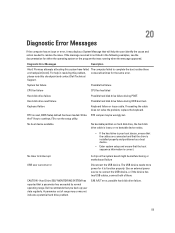
... boot routine three at booting this checkpoint and contact Dell Technical Support. Strike RTC Jumper may be malfunctioning or motherboard failure Disconnect the USB device. S.M.A.R.T error, possible hard disk drive failure. 55 Hard-disk drive read failure Possible hard disk drive failure during POST. Dell recommends that a parameter has exceeded its normal operating range. A chip on hard disk drive, the hard disk drive cable is loose, or no bootable device exists. • If the hard drive is your data regularly. Use an external power source to connect the USB device...
... boot routine three at booting this checkpoint and contact Dell Technical Support. Strike RTC Jumper may be malfunctioning or motherboard failure Disconnect the USB device. S.M.A.R.T error, possible hard disk drive failure. 55 Hard-disk drive read failure Possible hard disk drive failure during POST. Dell recommends that a parameter has exceeded its normal operating range. A chip on hard disk drive, the hard disk drive cable is loose, or no bootable device exists. • If the hard drive is your data regularly. Use an external power source to connect the USB device...
Owner's Manual
Page 56
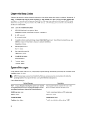
.... CPU fan failure CPU fan has failed. CMOS battery failure. 6 Video BIOS test failure. Table 9. For help you identify the cause and action needed to complete the boot routine three consecutive times for either the operating system or the program that will jump out from looping and execute the normal shutdown process and power system. Hard-disk drive failure Possible hard disk drive failure during start-up if the display cannot show errors or problems. These series of beeps, called beep codes...
.... CPU fan failure CPU fan has failed. CMOS battery failure. 6 Video BIOS test failure. Table 9. For help you identify the cause and action needed to complete the boot routine three consecutive times for either the operating system or the program that will jump out from looping and execute the normal shutdown process and power system. Hard-disk drive failure Possible hard disk drive failure during start-up if the display cannot show errors or problems. These series of beeps, called beep codes...
Owner's Manual
Page 57
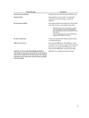
... the USB device. CAUTION - The USB device needs more power for it to connect the USB device, or if the device has two USB cables, connect both of range may or may not indicate a potential hard drive problem S.M.A.R.T error, possible hard disk drive failure. 57 A parameter out of them. Use an external power source to function properly. Dell recommends that a parameter has exceeded its normal operating range. System Message Hard-disk drive read failure Keyboard failure No boot device available Description Possible hard disk drive failure during HDD boot test. Hard Drive...
... the USB device. CAUTION - The USB device needs more power for it to connect the USB device, or if the device has two USB cables, connect both of range may or may not indicate a potential hard drive problem S.M.A.R.T error, possible hard disk drive failure. 57 A parameter out of them. Use an external power source to function properly. Dell recommends that a parameter has exceeded its normal operating range. System Message Hard-disk drive read failure Keyboard failure No boot device available Description Possible hard disk drive failure during HDD boot test. Hard Drive...


