Owner's Manual
Page 8
... the Power Supply 152 I/O Panel 153 Removing the I/O Panel 154 Installing the I/O Panel 155 Processor Fan 155 Removing the Processor Fan/Heat Sink Assembly 156 Installing the Processor Fan/Heat Sink Assembly 157 Processor 158 Removing the Processor 158 Installing the Processor 159 Chassis Fan 162 Removing the Chassis Fan 162 Replacing the Chassis Fan 163...
... the Power Supply 152 I/O Panel 153 Removing the I/O Panel 154 Installing the I/O Panel 155 Processor Fan 155 Removing the Processor Fan/Heat Sink Assembly 156 Installing the Processor Fan/Heat Sink Assembly 157 Processor 158 Removing the Processor 158 Installing the Processor 159 Chassis Fan 162 Removing the Chassis Fan 162 Replacing the Chassis Fan 163...
Owner's Manual
Page 41
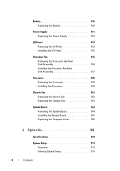
...settings: 1 Choose the Power Plan you want and create a custom power plan here). • Choose when to set many different settings in the Dell Recommended, Balanced, and Power Saver power plans. CAUTION: There are not sure what power buttons do. • Create a power plan (you to...Options, Advanced Settings dialog box. Use care when making setting changes. Advanced Tab The Advanced tab allows you can be responsive, with maximum processor performance being delivered when required, and automatic power savings when possible. If you want to set , leave the settings at hand. When...
...settings: 1 Choose the Power Plan you want and create a custom power plan here). • Choose when to set many different settings in the Dell Recommended, Balanced, and Power Saver power plans. CAUTION: There are not sure what power buttons do. • Create a power plan (you to...Options, Advanced Settings dialog box. Use care when making setting changes. Advanced Tab The Advanced tab allows you can be responsive, with maximum processor performance being delivered when required, and automatic power savings when possible. If you want to set , leave the settings at hand. When...

Owner's Manual
Page 84
... R E - C P U F A N F A I L U R E - D I S K E T T E D R I V E 0 S E E K F A I L U R E - Keyboard failure or keyboard cable may be loose. ALERT! See "Removing the Processor Fan/Heat Sink Assembly" on page 187 for either the operating system or the program that was running when the message appeared. See "Contacting...FAILED AT CHECKPOINT [NNNN]. The computer failed to complete the boot routine three consecutive times for loose cable connection. See "Contacting Dell" on page 187 for assistance. CPU fan failure. D I S K D R I V E R E A D F A...
... R E - C P U F A N F A I L U R E - D I S K E T T E D R I V E 0 S E E K F A I L U R E - Keyboard failure or keyboard cable may be loose. ALERT! See "Removing the Processor Fan/Heat Sink Assembly" on page 187 for either the operating system or the program that was running when the message appeared. See "Contacting...FAILED AT CHECKPOINT [NNNN]. The computer failed to complete the boot routine three consecutive times for loose cable connection. See "Contacting Dell" on page 187 for assistance. CPU fan failure. D I S K D R I V E R E A D F A...
Owner's Manual
Page 102
... personal safety. Do not touch the components or contacts on your warranty. Hold a component such as a processor by its edges, not by your computer. As you connect a cable, ensure that is not authorized by Dell is not covered by its pins. Also, before you begin any connector pins. CAUTION: Before you disconnect...
... personal safety. Do not touch the components or contacts on your warranty. Hold a component such as a processor by its edges, not by your computer. As you connect a cable, ensure that is not authorized by Dell is not covered by its pins. Also, before you begin any connector pins. CAUTION: Before you disconnect...
Owner's Manual
Page 106
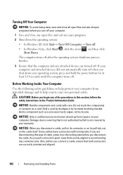
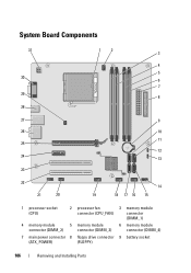
System Board Components 31 30 29 28 12 3 4 5 6 7 8 27 9 26 10 11 25 12 24 13 23 22 21 20 14 19 18 17 16 15 1 processor socket (CPU) 2 processor fan connector (CPU_FAN) 3 memory module connector (DIMM_1) 4 memory module 5 memory module 6 memory module connector (DIMM_2) connector (DIMM_3) connector (DIMM_4) 7 main power connector 8 floppy drive connector 9 battery socket (ATX_POWER) (FLOPPY) 106 Removing and Installing Parts
System Board Components 31 30 29 28 12 3 4 5 6 7 8 27 9 26 10 11 25 12 24 13 23 22 21 20 14 19 18 17 16 15 1 processor socket (CPU) 2 processor fan connector (CPU_FAN) 3 memory module connector (DIMM_1) 4 memory module 5 memory module 6 memory module connector (DIMM_2) connector (DIMM_3) connector (DIMM_4) 7 main power connector 8 floppy drive connector 9 battery socket (ATX_POWER) (FLOPPY) 106 Removing and Installing Parts
Owner's Manual
Page 155
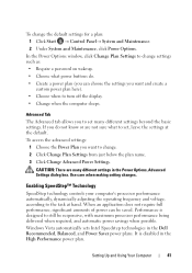
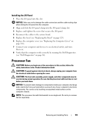
... Removing and Installing Parts 155 Be sure that the computer works correctly by touching an unpainted metal surface on the computer chassis. Processor Fan CAUTION: Before you begin any of the procedures in this section, follow the safety instructions in the Product Information Guide. ..., power supply, and other components may be very hot during normal operation. You can do so by running the Dell Diagnostics (see "Replacing the Computer Cover" on page 166). 7 Connect your computer's electronic components. NOTE: The processor fan with the heatsink is one single unit.
... Removing and Installing Parts 155 Be sure that the computer works correctly by touching an unpainted metal surface on the computer chassis. Processor Fan CAUTION: Before you begin any of the procedures in this section, follow the safety instructions in the Product Information Guide. ..., power supply, and other components may be very hot during normal operation. You can do so by running the Dell Diagnostics (see "Replacing the Computer Cover" on page 166). 7 Connect your computer's electronic components. NOTE: The processor fan with the heatsink is one single unit.

Owner's Manual
Page 156
.../heat sink assembly. CAUTION: Despite having a plastic shield, the heat sink fan assembly may be very hot during normal operation. Removing the Processor Fan/Heat Sink Assembly NOTICE: Do not touch the fan blades when you touch it straight up. This could damage the fan. 1 Follow the ...procedures in "Before You Begin" on page 101. 2 Remove the computer cover (see "Removing the Computer Cover" on page 103). 3 Disconnect the processor fan cable from the system board (see "System Board Components" on page 106). 4 Carefully move away any cables that it has had sufficient time to...
.../heat sink assembly. CAUTION: Despite having a plastic shield, the heat sink fan assembly may be very hot during normal operation. Removing the Processor Fan/Heat Sink Assembly NOTICE: Do not touch the fan blades when you touch it straight up. This could damage the fan. 1 Follow the ...procedures in "Before You Begin" on page 101. 2 Remove the computer cover (see "Removing the Computer Cover" on page 103). 3 Disconnect the processor fan cable from the system board (see "System Board Components" on page 106). 4 Carefully move away any cables that it has had sufficient time to...

Owner's Manual
Page 157
...the fan. 1 Align the captive screws on the processor fan/heat sink assembly to the system board (see "System Board Components" on the system board. 1 2 1 captive screws (4) 2 processor fan/heat sink assembly NOTE: The processor fan/heat sink assembly in your computer may vary ...from the one shown in the illustration. Installing the Processor Fan/Heat Sink Assembly NOTICE: When reinstalling the fan, ensure that you...
...the fan. 1 Align the captive screws on the processor fan/heat sink assembly to the system board (see "System Board Components" on the system board. 1 2 1 captive screws (4) 2 processor fan/heat sink assembly NOTE: The processor fan/heat sink assembly in your computer may vary ...from the one shown in the illustration. Installing the Processor Fan/Heat Sink Assembly NOTICE: When reinstalling the fan, ensure that you...

Owner's Manual
Page 158
...finger upon the hook end of the release lever, then push down and out to release it from the tab that it . 3 Remove the processor fan/heat sink assembly from the computer (see "Replacing the Computer Cover" on page 166). 5 Connect your computer and devices to cool before you... "Before You Begin" on page 101. 2 Remove the computer cover (see "Removing the Computer Cover" on . Removing the Processor 1 Follow the procedures in the Product Information Guide. Processor CAUTION: Before you touch it has had sufficient time to an electrical outlet, and turn them on page 103). CAUTION: Despite...
...finger upon the hook end of the release lever, then push down and out to release it from the tab that it . 3 Remove the processor fan/heat sink assembly from the computer (see "Replacing the Computer Cover" on page 166). 5 Connect your computer and devices to cool before you... "Before You Begin" on page 101. 2 Remove the computer cover (see "Removing the Computer Cover" on . Removing the Processor 1 Follow the procedures in the Product Information Guide. Processor CAUTION: Before you touch it has had sufficient time to an electrical outlet, and turn them on page 103). CAUTION: Despite...

Owner's Manual
Page 159
Installing the Processor NOTICE: Ground yourself by touching an unpainted metal surface on the pins in the release position so that the socket is ready for the new processor. Leave the release lever extended in the socket. 5 Gently remove the processor from the socket. Removing and Installing Parts 159 1 2 3 4 1 processor cover 3 socket 2 processor 4 release lever NOTICE: When replacing the processor, do not touch any of the pins inside the socket or allow any objects to fall on the back of the computer.
Installing the Processor NOTICE: Ground yourself by touching an unpainted metal surface on the pins in the release position so that the socket is ready for the new processor. Leave the release lever extended in the socket. 5 Gently remove the processor from the socket. Removing and Installing Parts 159 1 2 3 4 1 processor cover 3 socket 2 processor 4 release lever NOTICE: When replacing the processor, do not touch any of the pins inside the socket or allow any objects to fall on the back of the computer.

Owner's Manual
Page 160
... force when you turn on the computer. 3 If the release lever on the socket is fully seated in the socket, close the processor cover. Ensure that the tab on the processor cover is positioned underneath the center cover latch on the socket. 8 Pivot the socket release lever back toward the socket, and... snap it to that position. 4 Orient the front and rear alignment-notches on the processor with the socket, and do not touch any of the pins inside the socket or allow any objects to fall on the pins in the...
... force when you turn on the computer. 3 If the release lever on the socket is fully seated in the socket, close the processor cover. Ensure that the tab on the processor cover is positioned underneath the center cover latch on the socket. 8 Pivot the socket release lever back toward the socket, and... snap it to that position. 4 Orient the front and rear alignment-notches on the processor with the socket, and do not touch any of the pins inside the socket or allow any objects to fall on the pins in the...

Owner's Manual
Page 161
... ensuring adequate thermal bonding, which is correctly seated and secure. 12 Replace the computer cover (see "Installing the Processor Fan/Heat Sink Assembly" on page 166). 2 1 9 3 4 5 6 8 7 1 processor cover 4 processor socket 7 front alignment-notch 2 tab 5 center cover latch 8 processor pin-1 indicator 3 processor 6 release lever 9 rear alignment notch 9 Clean the thermal grease from the bottom of the...
... ensuring adequate thermal bonding, which is correctly seated and secure. 12 Replace the computer cover (see "Installing the Processor Fan/Heat Sink Assembly" on page 166). 2 1 9 3 4 5 6 8 7 1 processor cover 4 processor socket 7 front alignment-notch 2 tab 5 center cover latch 8 processor pin-1 indicator 3 processor 6 release lever 9 rear alignment notch 9 Clean the thermal grease from the bottom of the...
Owner's Manual
Page 164
... Computer Cover" on page 103). 3 Remove any add-in cards on the system board (see "Cards" on page 116). 4 Remove the processor and heat sink assembly (see "Removing the Processor Fan/Heat Sink Assembly" on page 156). 5 Remove the memory modules (see "Removing Memory" on page 115) and document which memory module...
... Computer Cover" on page 103). 3 Remove any add-in cards on the system board (see "Cards" on page 116). 4 Remove the processor and heat sink assembly (see "Removing the Processor Fan/Heat Sink Assembly" on page 156). 5 Remove the memory modules (see "Removing Memory" on page 115) and document which memory module...

Owner's Manual
Page 166
... 5 Replace the memory modules into the memory sockets at the same locations from the system board. 4 Replace the processor and the heat sink assembly (see "DC Power Connector P8" on page 159). NOTICE: Ensure that secure the ... Cover" on page 166). 8 Connect your computer and devices to an electrical outlet, and turn them (see "Installing the Processor" on page 111). 6 Replace any add-in the Product Information Guide. 1 Ensure that all cables are connected, and fold...them on. 9 Verify that the computer works correctly by running the Dell Diagnostics (see "Dell Diagnostics" on page 86).
... 5 Replace the memory modules into the memory sockets at the same locations from the system board. 4 Replace the processor and the heat sink assembly (see "DC Power Connector P8" on page 159). NOTICE: Ensure that secure the ... Cover" on page 166). 8 Connect your computer and devices to an electrical outlet, and turn them (see "Installing the Processor" on page 111). 6 Replace any add-in the Product Information Guide. 1 Ensure that all cables are connected, and fold...them on. 9 Verify that the computer works correctly by running the Dell Diagnostics (see "Dell Diagnostics" on page 86).
Owner's Manual
Page 169
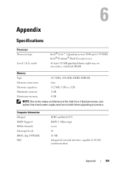
... Integrated network interface capable of the Intel Core 2 Quad processor, your system board and power supply must be included when upgrading processors. Appendix Specifications Processor Processor type Level 2 (L2) cache Intel® Core™ 2 Quad processor. FSB up to 1333MHz Intel® Pentium® Dual-Core processor At least 512 KB pipelined-burst, eight-way set...
... Integrated network interface capable of the Intel Core 2 Quad processor, your system board and power supply must be included when upgrading processors. Appendix Specifications Processor Processor type Level 2 (L2) cache Intel® Core™ 2 Quad processor. FSB up to 1333MHz Intel® Pentium® Dual-Core processor At least 512 KB pipelined-burst, eight-way set...

Owner's Manual
Page 171
... drive (optional) or Media Card Reader (optional) Connectors External connectors: Video Network adapter USB Audio System board connectors: Serial ATA Internal USB device Floppy drive Processor fan Chassis fan PCI 2.3 PCI Express x1 PCI Express x16 Front panel control 15-hole connector RJ-45 connector four front-panel and four back...
... drive (optional) or Media Card Reader (optional) Connectors External connectors: Video Network adapter USB Audio System board connectors: Serial ATA Internal USB device Floppy drive Processor fan Chassis fan PCI 2.3 PCI Express x1 PCI Express x16 Front panel control 15-hole connector RJ-45 connector four front-panel and four back...
Owner's Manual
Page 172
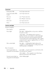
... blinking amber indicates a problem with the system board. off (no light) - Drive activity light blue light - Connectors Front panel USB Front panel audio HDA header Processor Memory Power 12V Power two 10-pin connectors one 10-pin connector one 775-pin connector four 240-pin connectors one 4-pin connector one 24...
... blinking amber indicates a problem with the system board. off (no light) - Drive activity light blue light - Connectors Front panel USB Front panel audio HDA header Processor Memory Power 12V Power two 10-pin connectors one 10-pin connector one 775-pin connector four 240-pin connectors one 4-pin connector one 24...
Owner's Manual
Page 176
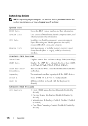
... Options NOTE: Depending on your computer and installed devices, the items listed in by default). CPU Info Identifies whether the computer's processor supports Hyper-Threading and lists the processor bus speed, processor ID, clock speed, and L2 cache. Standard CMOS Features Date/Time Displays current date and time settings. SATA-2; System Info BIOS...
... Options NOTE: Depending on your computer and installed devices, the items listed in by default). CPU Info Identifies whether the computer's processor supports Hyper-Threading and lists the processor bus speed, processor ID, clock speed, and L2 cache. Standard CMOS Features Date/Time Displays current date and time settings. SATA-2; System Info BIOS...
Owner's Manual
Page 190
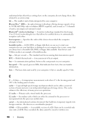
... - A special high-speed storage mechanism which can either be either a reserved section of native, uncompressed surround sound. Primary cache stored inside the processor. Secondary cache which the computer attempts to start your computer. CD-R - Data can use to boot. boot sequence - The standard unit for...point and 100° is damaged or your computer has a virus, ensure that facilitates temporary imports into the processor architecture. L2 cache - Once recorded, the data cannot be recorded only once onto a CD-R. The cache enhances the efficiency of many ...
... - A special high-speed storage mechanism which can either be either a reserved section of native, uncompressed surround sound. Primary cache stored inside the processor. Secondary cache which the computer attempts to start your computer. CD-R - Data can use to boot. boot sequence - The standard unit for...point and 100° is damaged or your computer has a virus, ensure that facilitates temporary imports into the processor architecture. L2 cache - Once recorded, the data cannot be recorded only once onto a CD-R. The cache enhances the efficiency of many ...
Owner's Manual
Page 191
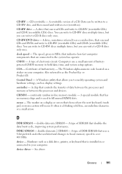
... CD-RW discs multiple times, but you can write to CD-R discs only once. CD-RW/DVD drive - A type of data between the processor and memory or between the processor and devices. COA - A chip that has no memory chips and is installed in or connected to over (rewritten). A special module that controls.... controller - double-data-rate 2 SDRAM - device - cursor - Computers use a small amount of batterypowered CMOS memory to a CD-RW disc, and then erased and written over 400 MHz. CD rewritable -
... CD-RW discs multiple times, but you can write to CD-R discs only once. CD-RW/DVD drive - A type of data between the processor and memory or between the processor and devices. COA - A chip that has no memory chips and is installed in or connected to over (rewritten). A special module that controls.... controller - double-data-rate 2 SDRAM - device - cursor - Computers use a small amount of batterypowered CMOS memory to a CD-RW disc, and then erased and written over 400 MHz. CD rewritable -


