Owner's Manual
Page 7
5 Removing and Installing Parts 101 Before You Begin 101 Recommended Tools 101 Turning Off Your Computer 102 Before Working Inside Your Computer 102 Removing the Computer Cover 103 Inside ...
5 Removing and Installing Parts 101 Before You Begin 101 Recommended Tools 101 Turning Off Your Computer 102 Before Working Inside Your Computer 102 Removing the Computer Cover 103 Inside ...
Owner's Manual
Page 42
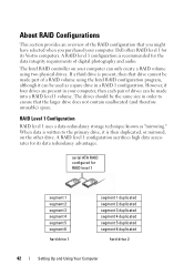
Dell offers RAID level 1 for its Vostro computers. If a third drive is recommended for RAID level 1 segment 1 segment 2 segment 3 segment 4 segment 5 segment 6 hard drive 1 segment 1 duplicated segment 2 duplicated segment 3 duplicated segment 4 ... A RAID level 1 configuration sacrifices high data access rates for its data redundancy advantages. A RAID level 1 configuration is present, then that drive cannot be made part of a RAID volume using two physical drives. When data is then duplicated, or mirrored, on your computer. However, if four drives are present in a RAID...
Dell offers RAID level 1 for its Vostro computers. If a third drive is recommended for RAID level 1 segment 1 segment 2 segment 3 segment 4 segment 5 segment 6 hard drive 1 segment 1 duplicated segment 2 duplicated segment 3 duplicated segment 4 ... A RAID level 1 configuration sacrifices high data access rates for its data redundancy advantages. A RAID level 1 configuration is present, then that drive cannot be made part of a RAID volume using two physical drives. When data is then duplicated, or mirrored, on your computer. However, if four drives are present in a RAID...
Owner's Manual
Page 59
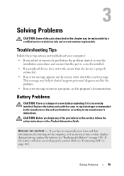
..." on page 187). CAUTION: Before you begin any of the parts described in this section, follow the safety instructions in the Product Information Guide. If you added or removed a part before the problem started, review the installation procedures and ensure that...P L A C E T H E B A T T E R Y - If the battery still does not work , ensure that the part is correctly installed. • If a peripheral device does not work properly, contact Dell (see "Contacting Dell" on page 150). Replace the battery only with the same or equivalent type recommended by a certified service technician...
..." on page 187). CAUTION: Before you begin any of the parts described in this section, follow the safety instructions in the Product Information Guide. If you added or removed a part before the problem started, review the installation procedures and ensure that...P L A C E T H E B A T T E R Y - If the battery still does not work , ensure that the part is correctly installed. • If a peripheral device does not work properly, contact Dell (see "Contacting Dell" on page 150). Replace the battery only with the same or equivalent type recommended by a certified service technician...
Owner's Manual
Page 101
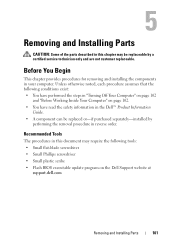
...Turning Off Your Computer" on page 102 and "Before Working Inside Your Computer" on the Dell Support website at support.dell.com Removing and Installing Parts 101 Removing and Installing Parts CAUTION: Some of the parts described in this document may be replaced or-if purchased separately-installed by a certified service... Small plastic scribe • Flash BIOS executable update program on page 102. • You have read the safety information in the Dell™ Product Information Guide. • A component can be replaceable by performing the removal procedure in reverse order.
...Turning Off Your Computer" on page 102 and "Before Working Inside Your Computer" on the Dell Support website at support.dell.com Removing and Installing Parts 101 Removing and Installing Parts CAUTION: Some of the parts described in this document may be replaced or-if purchased separately-installed by a certified service... Small plastic scribe • Flash BIOS executable update program on page 102. • You have read the safety information in the Dell™ Product Information Guide. • A component can be replaceable by performing the removal procedure in reverse order.
Owner's Manual
Page 102
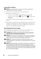
...finishes. 3 Ensure that the computer and any attached devices are turned off. As you connect a cable, ensure that is not authorized by Dell is not covered by your computer. CAUTION: Before you begin any of cable, press in the Product Information Guide. Also, before you ... help protect your computer from potential damage and to servicing that both connectors are correctly oriented and aligned. 102 Removing and Installing Parts Before Working Inside Your Computer Use the following safety guidelines to help ensure your operating system, press and hold the power button for...
...finishes. 3 Ensure that the computer and any attached devices are turned off. As you connect a cable, ensure that is not authorized by Dell is not covered by your computer. CAUTION: Before you begin any of cable, press in the Product Information Guide. Also, before you ... help protect your computer from potential damage and to servicing that both connectors are correctly oriented and aligned. 102 Removing and Installing Parts Before Working Inside Your Computer Use the following safety guidelines to help ensure your operating system, press and hold the power button for...

Owner's Manual
Page 103
Removing and Installing Parts 103 NOTICE: Ensure that you work, periodically touch an unpainted metal surface to dissipate static electricity, which it is resting. 2 Lay your computer on page ...
Removing and Installing Parts 103 NOTICE: Ensure that you work, periodically touch an unpainted metal surface to dissipate static electricity, which it is resting. 2 Lay your computer on page ...

Owner's Manual
Page 104
1 2 1 computer cover 2 front of computer 4 Release the computer cover by pulling it away from the front of the computer and lifting it up. 5 Set the cover aside in a secure location. 104 Removing and Installing Parts
1 2 1 computer cover 2 front of computer 4 Release the computer cover by pulling it away from the front of the computer and lifting it up. 5 Set the cover aside in a secure location. 104 Removing and Installing Parts
Owner's Manual
Page 105
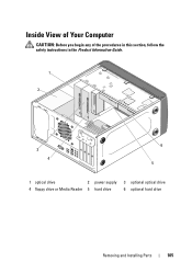
Inside View of Your Computer CAUTION: Before you begin any of the procedures in this section, follow the safety instructions in the Product Information Guide. 1 2 3 4 6 5 1 optical drive 2 power supply 3 optional optical drive 4 floppy drive or Media Reader 5 hard drive 6 optional hard drive Removing and Installing Parts 105
Inside View of Your Computer CAUTION: Before you begin any of the procedures in this section, follow the safety instructions in the Product Information Guide. 1 2 3 4 6 5 1 optical drive 2 power supply 3 optional optical drive 4 floppy drive or Media Reader 5 hard drive 6 optional hard drive Removing and Installing Parts 105
Owner's Manual
Page 106
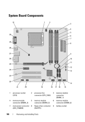
System Board Components 31 30 29 28 12 3 4 5 6 7 8 27 9 26 10 11 25 12 24 13 23 22 21 20 14 19 18 17 16 15 1 processor socket (CPU) 2 processor fan connector (CPU_FAN) 3 memory module connector (DIMM_1) 4 memory module 5 memory module 6 memory module connector (DIMM_2) connector (DIMM_3) connector (DIMM_4) 7 main power connector 8 floppy drive connector 9 battery socket (ATX_POWER) (FLOPPY) 106 Removing and Installing Parts
System Board Components 31 30 29 28 12 3 4 5 6 7 8 27 9 26 10 11 25 12 24 13 23 22 21 20 14 19 18 17 16 15 1 processor socket (CPU) 2 processor fan connector (CPU_FAN) 3 memory module connector (DIMM_1) 4 memory module 5 memory module 6 memory module connector (DIMM_2) connector (DIMM_3) connector (DIMM_4) 7 main power connector 8 floppy drive connector 9 battery socket (ATX_POWER) (FLOPPY) 106 Removing and Installing Parts
Owner's Manual
Page 108
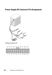
Power Supply DC Connector Pin Assignments DC Power Connector P1 13 14 15 16 17 18 19 20 21 22 23 24 1 2 3 4 5 6 7 8 9 10 11 12 108 Removing and Installing Parts
Power Supply DC Connector Pin Assignments DC Power Connector P1 13 14 15 16 17 18 19 20 21 22 23 24 1 2 3 4 5 6 7 8 9 10 11 12 108 Removing and Installing Parts

Owner's Manual
Page 109
Pin Number 1 2 3 4 5 6 7 8 9 10 11 12 13 14 15 16 17 18 19 20 21 22 23 24 Signal name 3.3 V 3.3 V RTN 5 V RTN 5 V RTN POK 5 V AUX +12 V +12 V 3.3 V +3.3 VDC +3.3 V Sense -12 V RTN PS_ON RTN RTN RTN OPEN 5 V 5 V 5 V RTN Wire Color Orange Orange Black Red Black Red Black Gray Purple Yellow Yellow Orange Orange Brown Blue Black Green Black Black Black Red Red Red Black Wire Size 20 AWG 20 AWG 20 AWG 20 AWG 20 AWG 20 AWG 20 AWG 22 AWG 20 AWG 20 AWG 20 AWG 20 AWG 20 AWG 22 AWG 22 AWG 20 AWG 22 AWG 20 AWG 20 AWG 20 AWG 20 AWG 20 AWG 20 AWG 20 AWG Removing and Installing Parts 109
Pin Number 1 2 3 4 5 6 7 8 9 10 11 12 13 14 15 16 17 18 19 20 21 22 23 24 Signal name 3.3 V 3.3 V RTN 5 V RTN 5 V RTN POK 5 V AUX +12 V +12 V 3.3 V +3.3 VDC +3.3 V Sense -12 V RTN PS_ON RTN RTN RTN OPEN 5 V 5 V 5 V RTN Wire Color Orange Orange Black Red Black Red Black Gray Purple Yellow Yellow Orange Orange Brown Blue Black Green Black Black Black Red Red Red Black Wire Size 20 AWG 20 AWG 20 AWG 20 AWG 20 AWG 20 AWG 20 AWG 22 AWG 20 AWG 20 AWG 20 AWG 20 AWG 20 AWG 22 AWG 22 AWG 20 AWG 22 AWG 20 AWG 20 AWG 20 AWG 20 AWG 20 AWG 20 AWG 20 AWG Removing and Installing Parts 109

Owner's Manual
Page 111
DC Power Connector P7 Pin Signal Color AWG Wire 1 +5 VDC Red 22 2 GND Black 22 3 GND Black 22 4 +12 VADC Yellow 22 DC Power Connector P8 123 456 Pin Signal Color AWG Wire 1 +12 VADC Yellow 22 2 +12 VADC Yellow 22 3 +12 VADC Yellow 22 4 GND Black 22 5 GND Black 22 6 GND Black 22 Removing and Installing Parts 111
DC Power Connector P7 Pin Signal Color AWG Wire 1 +5 VDC Red 22 2 GND Black 22 3 GND Black 22 4 +12 VADC Yellow 22 DC Power Connector P8 123 456 Pin Signal Color AWG Wire 1 +12 VADC Yellow 22 2 +12 VADC Yellow 22 3 +12 VADC Yellow 22 4 GND Black 22 5 GND Black 22 6 GND Black 22 Removing and Installing Parts 111
Owner's Manual
Page 112
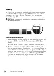
... pair of DDR2 533-MHz and DDR2 667-MHz and 800 MHz memory, the modules function at the slowest speed installed. 112 Removing and Installing Parts Memory Installation Guidelines • DIMM connectors must install it in connector DIMM_1. • For best performance, memory modules should be populated in performance. (See the...
... pair of DDR2 533-MHz and DDR2 667-MHz and 800 MHz memory, the modules function at the slowest speed installed. 112 Removing and Installing Parts Memory Installation Guidelines • DIMM connectors must install it in connector DIMM_1. • For best performance, memory modules should be populated in performance. (See the...
Owner's Manual
Page 113
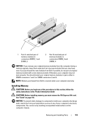
.... You should install your original memory modules in pairs either in the Product Information Guide. NOTE: Memory purchased from Dell. CAUTION: Before installing memory, you touch any of your body before you must remove the PCI Express X16 card. Removing and Installing... Parts 113 NOTICE: To prevent static damage to components inside your computer, discharge static electricity from your computer's electronic components. Installing Memory...
.... You should install your original memory modules in pairs either in the Product Information Guide. NOTE: Memory purchased from Dell. CAUTION: Before installing memory, you touch any of your body before you must remove the PCI Express X16 card. Removing and Installing... Parts 113 NOTICE: To prevent static damage to components inside your computer, discharge static electricity from your computer's electronic components. Installing Memory...
Owner's Manual
Page 114
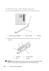
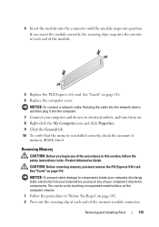
1 Follow the procedures in "Before You Begin" on page 101. 2 Press the securing clip at each end of the memory module connector. 1 2 3 1 memory connector (DIMM_1) 2 securing clips (2) 3 connector 3 Align the notch on the bottom of the module with the crossbar in the connector. 3 2 1 4 1 cutouts (2) 3 notch 2 memory module 4 crossbar NOTICE: To avoid damage to the memory module, press the module straight down into the connector while you apply equal force to each end of the module. 114 Removing and Installing Parts
1 Follow the procedures in "Before You Begin" on page 101. 2 Press the securing clip at each end of the memory module connector. 1 2 3 1 memory connector (DIMM_1) 2 securing clips (2) 3 connector 3 Align the notch on the bottom of the module with the crossbar in the connector. 3 2 1 4 1 cutouts (2) 3 notch 2 memory module 4 crossbar NOTICE: To avoid damage to the memory module, press the module straight down into the connector while you apply equal force to each end of the module. 114 Removing and Installing Parts
Owner's Manual
Page 115
... click Properties. 9 Click the General tab. 10 To verify that the memory is installed correctly, check the amount of memory (RAM) listed. Removing and Installing Parts 115 Removing Memory CAUTION: Before you touch any of the procedures in this section, follow the safety instructions in "Before You Begin" on the computer...
... click Properties. 9 Click the General tab. 10 To verify that the memory is installed correctly, check the amount of memory (RAM) listed. Removing and Installing Parts 115 Removing Memory CAUTION: Before you touch any of the procedures in this section, follow the safety instructions in "Before You Begin" on the computer...
Owner's Manual
Page 116
... surface on page 116. NOTICE: To prevent static damage to components inside your computer, discharge static electricity from the operating system. 116 Removing and Installing Parts 3 Grasp the module at the end of your computer's electronic components. Cards CAUTION: Before you begin any of the board and lift up. 4 Replace the...
... surface on page 116. NOTICE: To prevent static damage to components inside your computer, discharge static electricity from the operating system. 116 Removing and Installing Parts 3 Grasp the module at the end of your computer's electronic components. Cards CAUTION: Before you begin any of the board and lift up. 4 Replace the...

Owner's Manual
Page 117
... then ease it aside in a secure place. 5 If you are replacing a card that is already installed in the computer, remove the card. Removing and Installing Parts 117 See "Removing the Computer Cover" on page 101. 2 Remove the computer cover.
... then ease it aside in a secure place. 5 If you are replacing a card that is already installed in the computer, remove the card. Removing and Installing Parts 117 See "Removing the Computer Cover" on page 101. 2 Remove the computer cover.

Owner's Manual
Page 118
... computer when they are connected to unplug your computer. See the documentation that the card is fully seated in the slot. 118 Removing and Installing Parts NOTE: The position of slot 9 If you are replacing may vary from the illustration. 7 Prepare the card for your computer from its electrical outlet before...
... computer when they are connected to unplug your computer. See the documentation that the card is fully seated in the slot. 118 Removing and Installing Parts NOTE: The position of slot 9 If you are replacing may vary from the illustration. 7 Prepare the card for your computer from its electrical outlet before...

Owner's Manual
Page 119
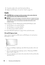
1 2 3 4 5 1 PCI Express x16 card 4 PCI Express x1 card slot 2 securing tab 5 PCI Express x16 card slot 3 PCI Express x1 card 11 Replace the card retention bracket ensuring that: • The guide clamp is aligned with the guide notch. • The tops of all cards and filler brackets are flush with the alignment bar. • The notch in the top of the card or filler bracket fits around the alignment guide. Removing and Installing Parts 119
1 2 3 4 5 1 PCI Express x16 card 4 PCI Express x1 card slot 2 securing tab 5 PCI Express x16 card slot 3 PCI Express x1 card 11 Replace the card retention bracket ensuring that: • The guide clamp is aligned with the guide notch. • The tops of all cards and filler brackets are flush with the alignment bar. • The notch in the top of the card or filler bracket fits around the alignment guide. Removing and Installing Parts 119

