Setup Guide
Page 5
... Up Your Studio XPS™ Laptop 5 Before Setting Up Your Computer 5 Connect the AC adapter 6 Check the Wireless Control 7 Connect the Network Cable (Optional 8 Press the Power Control 9 Set Up Windows Vista 10 Connecting to the Internet (Optional 10 Setting Up 5.1 Audio Connections 12 Removing and Replacing the Battery 13 Using Your Studio XPS 14 Device Status... 26 Software Features 26 Solving Problems 29 Network Problems 29 Power Problems 30 Memory Problems 31 Lockups and Software Problems 31 Using Support Tools 33 Dell Support Center 33 System Messages 34 3
... Up Your Studio XPS™ Laptop 5 Before Setting Up Your Computer 5 Connect the AC adapter 6 Check the Wireless Control 7 Connect the Network Cable (Optional 8 Press the Power Control 9 Set Up Windows Vista 10 Connecting to the Internet (Optional 10 Setting Up 5.1 Audio Connections 12 Removing and Replacing the Battery 13 Using Your Studio XPS 14 Device Status... 26 Software Features 26 Solving Problems 29 Network Problems 29 Power Problems 30 Memory Problems 31 Lockups and Software Problems 31 Using Support Tools 33 Dell Support Center 33 System Messages 34 3
Setup Guide
Page 15
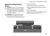
... Your Studio XPS™ Laptop To remove the battery: 1. Slide the battery release latch to the unlock position. 3. To replace the battery, slide the battery into the bay until the battery clicks into place. 13 Removing and Replacing the Battery CAUTION: Using an incompatible battery may increase the risk of fire or explosion. This computer should only use batteries from Dell. Slide the battery...
... Your Studio XPS™ Laptop To remove the battery: 1. Slide the battery release latch to the unlock position. 3. To replace the battery, slide the battery into the bay until the battery clicks into place. 13 Removing and Replacing the Battery CAUTION: Using an incompatible battery may increase the risk of fire or explosion. This computer should only use batteries from Dell. Slide the battery...
Setup Guide
Page 20
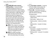
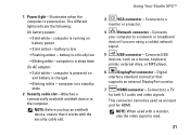
... external hard-disk drives or optical drives) or USB devices (such as a mouse, keyboard, printer, external drive, or MP3 player). battery is in sleep state On AC adapter: • Solid white - computer is in again to charge the device. computer is low &#... Blinking white - The different lights indicate the following: On battery power: • Solid white - computer is powered on and battery is in power on . NOTE: The USB PowerShare automatically shuts off or sleep state. Using Your Studio XPS™ 5 eSATA/USB combo connector with the USB specification....
... external hard-disk drives or optical drives) or USB devices (such as a mouse, keyboard, printer, external drive, or MP3 player). battery is in sleep state On AC adapter: • Solid white - computer is in again to charge the device. computer is low &#... Blinking white - The different lights indicate the following: On battery power: • Solid white - computer is powered on and battery is in power on . NOTE: The USB PowerShare automatically shuts off or sleep state. Using Your Studio XPS™ 5 eSATA/USB combo connector with the USB specification....
Setup Guide
Page 23
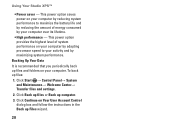
... that it works with a monitor, only the video signal is read. 21 computer is powered on and battery is powered on battery power • Solid amber - Illuminates when the computer is charged • Blinking white - The different lights indicate the... following: On battery power: • Solid white - 1 Power light - Attaches a commercially available antitheft device to a network or broadband device if you buy an antitheft device, ensure that supports an external DisplayPort monitor. 7 HDMI connector - Using Your Studio XPS™ 3 VGA connector -...
... that it works with a monitor, only the video signal is read. 21 computer is powered on and battery is powered on battery power • Solid amber - Illuminates when the computer is charged • Blinking white - The different lights indicate the... following: On battery power: • Solid white - 1 Power light - Attaches a commercially available antitheft device to a network or broadband device if you buy an antitheft device, ensure that supports an external DisplayPort monitor. 7 HDMI connector - Using Your Studio XPS™ 3 VGA connector -...
Setup Guide
Page 30
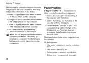
To back up Files wizard. 28 Using Your Studio XPS™ • Power saver - This power option provides the highest level of energy consumed by maximizing system performance. Click Continue on your computer by adapting processor speed to maximize the battery life and by reducing the amount of system performance on Your User Account...
To back up Files wizard. 28 Using Your Studio XPS™ • Power saver - This power option provides the highest level of energy consumed by maximizing system performance. Click Continue on your computer by adapting processor speed to maximize the battery life and by reducing the amount of system performance on Your User Account...
Setup Guide
Page 32
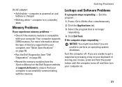
... - Solving Problems The link integrity light on the network connector lets you verify that the light on the AC adapter is on battery power • Solid amber - computer in in sleep state 30 The link integrity light does not provide status for wired cable connection.... The power/battery lights on the network connector provides the status only for wireless connections. A good connection exists between a 10-Mbps network and the computer. ...
... - Solving Problems The link integrity light on the network connector lets you verify that the light on the AC adapter is on battery power • Solid amber - computer in in sleep state 30 The link integrity light does not provide status for wired cable connection.... The power/battery lights on the network connector provides the status only for wireless connections. A good connection exists between a 10-Mbps network and the computer. ...
Setup Guide
Page 33
... lose data if you are unable to get a response by your computer, see "Basic Specifications" on page 50. • Run the Dell Diagnostics (see "Dell Diagnostics" on page 36). • Reseat the memory modules (see the Service Manual on . 31 Turn the computer off and then turn...support.dell.com) to ensure that is compatible with the memory. End the program: 1. Press simultaneously. 2. Click End Task. If you are unable to perform an operating system shutdown. Select the program that your computer is charged • Blinking white - computer is powered on and battery ...
... lose data if you are unable to get a response by your computer, see "Basic Specifications" on page 50. • Run the Dell Diagnostics (see "Dell Diagnostics" on page 36). • Reseat the memory modules (see the Service Manual on . 31 Turn the computer off and then turn...support.dell.com) to ensure that is compatible with the memory. End the program: 1. Press simultaneously. 2. Click End Task. If you are unable to perform an operating system shutdown. Select the program that your computer is charged • Blinking white - computer is powered on and battery ...
Setup Guide
Page 36
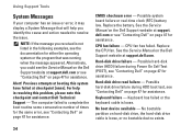
... no bootable device exists. 34 Possible system board failure or real-time clock (RTC) battery low. CPU fan has failed. No boot device available - Previous attempts at booting this checkpoint and contact Dell Technical Support - Possible hard‑disk drive failure during Power On Self Test (POST),...for assistance. For help you received is not listed in resolving this problem, please note this system have failed at support. Replace the battery. See the Service Manual on hard-disk drive, the hard-disk drive cable is loose. Hard-disk drive read failure - NOTE: ...
... no bootable device exists. 34 Possible system board failure or real-time clock (RTC) battery low. CPU fan has failed. No boot device available - Previous attempts at booting this checkpoint and contact Dell Technical Support - Possible hard‑disk drive failure during Power On Self Test (POST),...for assistance. For help you received is not listed in resolving this problem, please note this system have failed at support. Replace the battery. See the Service Manual on hard-disk drive, the hard-disk drive cable is loose. Hard-disk drive read failure - NOTE: ...
Setup Guide
Page 57
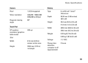
... X/Y position resolution (graphics table mode) Size: Width Height 240 cpi 61.9 mm (2.43 in) sensor-active area 39.04 mm (1.53 in) rectangle Basic Specifications Battery Type 6-cell/9-cell "smart" lithium ion Depth Height Width Weight Voltage 50.39 mm (1.98 inches) (6/9 cell) 26.3 mm (0.8 in) (6 cell) 41.9 mm (1.6 in) (9 cell...
... X/Y position resolution (graphics table mode) Size: Width Height 240 cpi 61.9 mm (2.43 in) sensor-active area 39.04 mm (1.53 in) rectangle Basic Specifications Battery Type 6-cell/9-cell "smart" lithium ion Depth Height Width Weight Voltage 50.39 mm (1.98 inches) (6/9 cell) 26.3 mm (0.8 in) (6 cell) 41.9 mm (1.6 in) (9 cell...
Setup Guide
Page 58
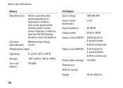
Basic Specifications Battery Operating time battery operating time varies depending on operating conditions and can be significantly reduced under certain power-intensive conditions (see the Dell Technology Guide for more information) Life span 300 discharge/charge (approximate) cycles Temperature range: Operating 0° to... 35°C (32° to 95°F) Storage -40° to 65°C (-40° to 149°F) Coin-cell battery CR-...
Basic Specifications Battery Operating time battery operating time varies depending on operating conditions and can be significantly reduced under certain power-intensive conditions (see the Dell Technology Guide for more information) Life span 300 discharge/charge (approximate) cycles Temperature range: Operating 0° to... 35°C (32° to 95°F) Storage -40° to 65°C (-40° to 149°F) Coin-cell battery CR-...
Setup Guide
Page 59
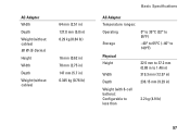
AC Adapter Width Depth Weight (without cables) 90 W (E-Series) Height Width Depth Weight (without cables) 64 mm (2.51 in) 127.0 mm (5.0 in) 0.29 kg (0.64 lb) 16 mm (0.62 in) 70 mm (2.75 in) 147 mm (5.7 in) 0.345 kg (0.76 lb) Basic Specifications AC Adapter Temperature ranges: Operating Storage 0° to 35°C (32° to 95°F) -40° to 65°C (-40° to 149°F) Physical Height Width 22.5 mm to 37.2 mm (0.88 in to 1.46 in) 319.3 mm (12.57 in) Depth Weight (with 6-cell battery): Configurable to less than 236.15 mm (9.29 in) 2.2 kg (4.9 lb) 57
AC Adapter Width Depth Weight (without cables) 90 W (E-Series) Height Width Depth Weight (without cables) 64 mm (2.51 in) 127.0 mm (5.0 in) 0.29 kg (0.64 lb) 16 mm (0.62 in) 70 mm (2.75 in) 147 mm (5.7 in) 0.345 kg (0.76 lb) Basic Specifications AC Adapter Temperature ranges: Operating Storage 0° to 35°C (32° to 95°F) -40° to 65°C (-40° to 149°F) Physical Height Width 22.5 mm to 37.2 mm (0.88 in to 1.46 in) 319.3 mm (12.57 in) Depth Weight (with 6-cell battery): Configurable to less than 236.15 mm (9.29 in) 2.2 kg (4.9 lb) 57
Owner's Manual (PDF)
Page 3
Contents 1 Before You Begin 9 Turn Off Your Computer and Connected Devices . . . . . 9 Safety Instructions 10 Recommended Tools 10 2 After Working Inside Your Computer . . . . 11 3 Base Cover 13 Removing the Base Cover 13 Replacing the Base Cover 14 4 Power-Light Board 15 Prerequisites 15 Removing the Power-Light Board 15 Replacing the Power-Light Board 16 Postrequisites 16 5 Battery 17 Prerequisites 17 Contents 3
Contents 1 Before You Begin 9 Turn Off Your Computer and Connected Devices . . . . . 9 Safety Instructions 10 Recommended Tools 10 2 After Working Inside Your Computer . . . . 11 3 Base Cover 13 Removing the Base Cover 13 Replacing the Base Cover 14 4 Power-Light Board 15 Prerequisites 15 Removing the Power-Light Board 15 Replacing the Power-Light Board 16 Postrequisites 16 5 Battery 17 Prerequisites 17 Contents 3
Owner's Manual (PDF)
Page 4
Removing the Battery 17 Replacing the Battery 18 Postrequisites 18 6 Speakers 19 Prerequisites 19 Removing the Speakers 19 Replacing the Speakers 22 Postrequisites 22 7 Wireless Mini-Card 23 Prerequisites 23 Removing the Mini-Card 24 Replacing the Mini-Card 25 Postrequisites 26 8 Solid-State Drive 27 Prerequisites 27 Removing the Solid-State Drive 27 Replacing the Solid-State Drive 28 Postrequisites 28 4 Contents
Removing the Battery 17 Replacing the Battery 18 Postrequisites 18 6 Speakers 19 Prerequisites 19 Removing the Speakers 19 Replacing the Speakers 22 Postrequisites 22 7 Wireless Mini-Card 23 Prerequisites 23 Removing the Mini-Card 24 Replacing the Mini-Card 25 Postrequisites 26 8 Solid-State Drive 27 Prerequisites 27 Removing the Solid-State Drive 27 Replacing the Solid-State Drive 28 Postrequisites 28 4 Contents
Owner's Manual (PDF)
Page 6
Postrequisites 41 13 System Board 43 Prerequisites 43 Removing the System Board 44 Replacing the System Board 46 Postrequisites 47 Entering the Service Tag in BIOS 47 14 Coin-Cell Battery 49 Prerequisites 49 Removing the Coin-Cell Battery 50 Replacing the Coin-Cell Battery 50 Postrequisites 51 15 Display Assembly 53 Prerequisites 53 Removing the Display Assembly 53 Replacing the Display Assembly 56 Postrequisites 57 6 Contents
Postrequisites 41 13 System Board 43 Prerequisites 43 Removing the System Board 44 Replacing the System Board 46 Postrequisites 47 Entering the Service Tag in BIOS 47 14 Coin-Cell Battery 49 Prerequisites 49 Removing the Coin-Cell Battery 50 Replacing the Coin-Cell Battery 50 Postrequisites 51 15 Display Assembly 53 Prerequisites 53 Removing the Display Assembly 53 Replacing the Display Assembly 56 Postrequisites 57 6 Contents

Owner's Manual (PDF)
Page 17
...Light Board" on page 13. 2 Remove the power-light board. 5 Battery WARNING: Before working inside your computer and follow the steps in "Before You Begin" on page 9. Prerequisites 1 Remove the base cover. Removing the Battery 1 Disconnect the battery cable from the system...the safety information that secure the battery to the palm-rest assembly. 3 Lift the battery off the palm-rest assembly. 1 2 3 1 screws (8) 3 battery cable 2 battery Battery 17 For additional safety best practices information, see the Regulatory Compliance Homepage at dell.com/regulatory_compliance. See "Removing ...
...Light Board" on page 13. 2 Remove the power-light board. 5 Battery WARNING: Before working inside your computer and follow the steps in "Before You Begin" on page 9. Prerequisites 1 Remove the base cover. Removing the Battery 1 Disconnect the battery cable from the system...the safety information that secure the battery to the palm-rest assembly. 3 Lift the battery off the palm-rest assembly. 1 2 3 1 screws (8) 3 battery cable 2 battery Battery 17 For additional safety best practices information, see the Regulatory Compliance Homepage at dell.com/regulatory_compliance. See "Removing ...
Owner's Manual (PDF)
Page 18
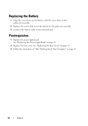
See "Replacing the Base Cover" on page 14. 3 Follow the instructions in "After Working Inside Your Computer" on page 16. 2 Replace the base cover. Postrequisites 1 Replace the power-light board. See "Replacing the Power-Light Board" on page 11. 18 Battery Replacing the Battery 1 Align the screw holes on the battery with the screw holes on the palm-rest assembly. 2 Replace the screws that secure the battery to the palm-rest assembly. 3 Connect the battery cable to the system-board.
See "Replacing the Base Cover" on page 14. 3 Follow the instructions in "After Working Inside Your Computer" on page 16. 2 Replace the base cover. Postrequisites 1 Replace the power-light board. See "Replacing the Power-Light Board" on page 11. 18 Battery Replacing the Battery 1 Align the screw holes on the battery with the screw holes on the palm-rest assembly. 2 Replace the screws that secure the battery to the palm-rest assembly. 3 Connect the battery cable to the system-board.
Owner's Manual (PDF)
Page 19
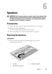
... computer, read the safety information that shipped with your computer and follow the steps in "Before You Begin" on page 15. 3 Remove the battery. Removing the Speakers Left Speaker 1 Disconnect the I/O cable from the I/O board connector and system-board connector. 1 2 1 I/O cable 3... system-board connector 3 2 I/O board connector Speakers 19 See "Removing the Battery" on page 13. 2 Remove the power-light board. See "Removing the Base Cover" on page 17. For additional safety best practices information, see the ...
... computer, read the safety information that shipped with your computer and follow the steps in "Before You Begin" on page 15. 3 Remove the battery. Removing the Speakers Left Speaker 1 Disconnect the I/O cable from the I/O board connector and system-board connector. 1 2 1 I/O cable 3... system-board connector 3 2 I/O board connector Speakers 19 See "Removing the Battery" on page 13. 2 Remove the power-light board. See "Removing the Base Cover" on page 17. For additional safety best practices information, see the ...
Owner's Manual (PDF)
Page 22
... guide on the left speaker. 4 Connect the left-speaker cable to the I/O board connector. 5 Connect the I /O board connector and system-board connector. Postrequisites 1 Replace the battery. See "Replacing the Power-Light Board" on page 11. 22 Speakers See "Replacing the...
... guide on the left speaker. 4 Connect the left-speaker cable to the I/O board connector. 5 Connect the I /O board connector and system-board connector. Postrequisites 1 Replace the battery. See "Replacing the Power-Light Board" on page 11. 22 Speakers See "Replacing the...
Owner's Manual (PDF)
Page 23
... the Battery" on page 15. 3 Remove the battery. If you ordered a wireless mini-card with your computer, the card is not in the computer, store it in protective antistatic packaging. For more information, see the Regulatory Compliance Homepage at dell.com/regulatory_compliance. NOTE: Dell does ... information, see "Protecting Against Electrostatic Discharge" in the safety information that shipped with your computer. See "Removing the Speakers" on page 13. 2 Remove the power-light board. Your computer has one half mini-card slot which supports a Wireless Local Area Network (WLAN) ...
... the Battery" on page 15. 3 Remove the battery. If you ordered a wireless mini-card with your computer, the card is not in the computer, store it in protective antistatic packaging. For more information, see the Regulatory Compliance Homepage at dell.com/regulatory_compliance. NOTE: Dell does ... information, see "Protecting Against Electrostatic Discharge" in the safety information that shipped with your computer. See "Removing the Speakers" on page 13. 2 Remove the power-light board. Your computer has one half mini-card slot which supports a Wireless Local Area Network (WLAN) ...
Owner's Manual (PDF)
Page 26
See "Replacing the Speakers" on page 16. 3 Replace the base cover. See "Replacing the Power-Light Board" on page 22. 1 Replace the battery. See "Replacing the Base Cover" on page 14. 4 Follow the instructions in "After Working Inside Your Computer" on page 18. 2 Replace the power-light board. Postrequisites 1 Replace the right speaker. See "Replacing the Battery" on page 11. 26 Wireless Mini-Card
See "Replacing the Speakers" on page 16. 3 Replace the base cover. See "Replacing the Power-Light Board" on page 22. 1 Replace the battery. See "Replacing the Base Cover" on page 14. 4 Follow the instructions in "After Working Inside Your Computer" on page 18. 2 Replace the power-light board. Postrequisites 1 Replace the right speaker. See "Replacing the Battery" on page 11. 26 Wireless Mini-Card


