Setup Guide
Page 17
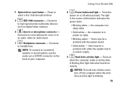
...to an audio cable for audio input. 7 Headphone connector - Turns on or off the computer while the hard drive activity light is in power-on the back of data, never turn off when pressed. there may be a problem with the system board. •...with either the system board or power supply. 9 Hard drive activity light - The light in or microphone connector - 4 Optical drive eject button - Connects to eject a disc from the optical drive. 5 IEEE 1394 connector - Using Your Studio 540 8 Power button and light - A blinking blue light indicates hard drive activity.
...to an audio cable for audio input. 7 Headphone connector - Turns on or off the computer while the hard drive activity light is in power-on the back of data, never turn off when pressed. there may be a problem with the system board. •...with either the system board or power supply. 9 Hard drive activity light - The light in or microphone connector - 4 Optical drive eject button - Connects to eject a disc from the optical drive. 5 IEEE 1394 connector - Using Your Studio 540 8 Power button and light - A blinking blue light indicates hard drive activity.
Setup Guide
Page 19
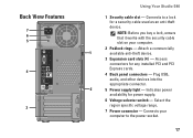
.... 2 Padlock rings - Attach a commercially 1 available anti-theft device. 3 Expansion card slots (4) - Select the region specific voltage range. 7 Power connector - Plug USB, audio, and other devices into the appropriate connector. 2 5 Power supply light - Back View Features 7 6 5 4 3 Using Your Studio 540 1 Security cable slot - NOTE: Before you buy a lock, ensure that it works with the security cable slot...
.... 2 Padlock rings - Attach a commercially 1 available anti-theft device. 3 Expansion card slots (4) - Select the region specific voltage range. 7 Power connector - Plug USB, audio, and other devices into the appropriate connector. 2 5 Power supply light - Back View Features 7 6 5 4 3 Using Your Studio 540 1 Security cable slot - NOTE: Before you buy a lock, ensure that it works with the security cable slot...


