Setup Guide
Page 5
...8 Connect the Network Cable (Optional 9 Connect the Power Cables for Your Display and Computer 10 Press the Power Buttons on Your Computer and Display 10 Windows Vista Setup 11 Connect to the Internet (Optional 11 Using Your Studio 540 14 Front View Features 14 Back View Features 17 ...Back Panel Connectors 18 Software Features 20 Solving Problems 22 Network Problems 22 Power Problems 23 Memory Problems 25 Lockups and Software Problems 26 Using Support Tools 28 Dell Support Center 28 System ...
...8 Connect the Network Cable (Optional 9 Connect the Power Cables for Your Display and Computer 10 Press the Power Buttons on Your Computer and Display 10 Windows Vista Setup 11 Connect to the Internet (Optional 11 Using Your Studio 540 14 Front View Features 14 Back View Features 17 ...Back Panel Connectors 18 Software Features 20 Solving Problems 22 Network Problems 22 Power Problems 23 Memory Problems 25 Lockups and Software Problems 26 Using Support Tools 28 Dell Support Center 28 System ...

Setup Guide
Page 7
Restricting airflow around your computer in an enclosed space, such as a cabinet or drawer when it to place your Studio 540 and connecting peripherals. To prevent overheating ensure that you leave at least 10.2 cm (4 inches) at the back of the computer... Computer When positioning your computer, ensure that you allow easy access to a power source, adequate ventilation, and a level surface to overheat. You should never place your Studio 540 may cause it is powered on all other sides. Setting Up Your Studio 540 This section provides information about setting up your computer.
Restricting airflow around your computer in an enclosed space, such as a cabinet or drawer when it to place your Studio 540 and connecting peripherals. To prevent overheating ensure that you leave at least 10.2 cm (4 inches) at the back of the computer... Computer When positioning your computer, ensure that you allow easy access to a power source, adequate ventilation, and a level surface to overheat. You should never place your Studio 540 may cause it is powered on all other sides. Setting Up Your Studio 540 This section provides information about setting up your computer.

Setup Guide
Page 12
Setting Up Your Studio 540 Connect the Power Cables for Your Display and Computer Press the Power Buttons on Your Computer and Display 10
Setting Up Your Studio 540 Connect the Power Cables for Your Display and Computer Press the Power Buttons on Your Computer and Display 10
Setup Guide
Page 17
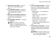
...; Solid white - Press to high-speed serial multimedia devices such as digital video cameras. 6 Line-in power-on the back of your computer. Turns the power on when the computer reads or writes data. the computer is in or microphone connector - there may be...this button indicates the power state: • Blinking white - Connects to eject a disc from the optical drive. 5 IEEE 1394 connector - Connects to a microphone for voice or to an audio cable for audio input. 7 Headphone connector - 4 Optical drive eject button - Using Your Studio 540 8 Power button and light -...
...; Solid white - Press to high-speed serial multimedia devices such as digital video cameras. 6 Line-in power-on the back of your computer. Turns the power on when the computer reads or writes data. the computer is in or microphone connector - there may be...this button indicates the power state: • Blinking white - Connects to eject a disc from the optical drive. 5 IEEE 1394 connector - Connects to a microphone for voice or to an audio cable for audio input. 7 Headphone connector - 4 Optical drive eject button - Using Your Studio 540 8 Power button and light -...
Setup Guide
Page 19
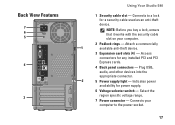
... 6 5 4 3 Using Your Studio 540 1 Security cable slot - Connects to the power socket. 17 Access connectors for power supply. 6 Voltage selector switch - Indicates power availability for any installed PCI and PCI Express cards. 4 Back panel connectors - Plug USB, audio, and other devices into the appropriate connector. 2 5 Power supply light - Connects your computer...a lock for a security cable used as an anti-theft device. Select the region specific voltage range. 7 Power connector - Attach a commercially 1 available anti-theft device. 3 Expansion card slots (4) -
... 6 5 4 3 Using Your Studio 540 1 Security cable slot - Connects to the power socket. 17 Access connectors for power supply. 6 Voltage selector switch - Indicates power availability for any installed PCI and PCI Express cards. 4 Back panel connectors - Plug USB, audio, and other devices into the appropriate connector. 2 5 Power supply light - Connects your computer...a lock for a security cable used as an anti-theft device. Select the region specific voltage range. 7 Power connector - Attach a commercially 1 available anti-theft device. 3 Expansion card slots (4) -

Setup Guide
Page 23
...8226; High performance - Click Back up files or Back up files: 1. Using Your Studio 540 Customizing Your Energy Settings You can use the power options in the Back up Files wizard. 21 This power option offers full performance when you periodically back up files and folders on your computer by...; Balanced - Backing Up Your Data It is recommended that you need it and saves power during periods of system performance on your computer by adapting processor speed to configure the power settings on Your User Account Control dialog box and follow the instructions in your operating system...
...8226; High performance - Click Back up files or Back up files: 1. Using Your Studio 540 Customizing Your Energy Settings You can use the power options in the Back up Files wizard. 21 This power option offers full performance when you periodically back up files and folders on your computer by...; Balanced - Backing Up Your Data It is recommended that you need it and saves power during periods of system performance on your computer by adapting processor speed to configure the power settings on Your User Account Control dialog box and follow the instructions in your operating system...


