
Hardware Manual
Page 3
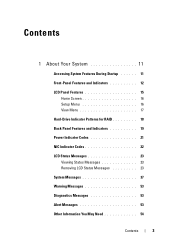
Contents 1 About Your System 11 Accessing System Features During Startup 11 Front-Panel Features and Indicators 12 LCD Panel Features 15 Home Screen 16 Setup Menu 16 View Menu 17 Hard-Drive Indicator Patterns for RAID 18 Back Panel Features and Indicators 19 Power Indicator Codes 21 NIC Indicator Codes 22 LCD Status Messages 23 Viewing Status Messages 23 Removing LCD Status Messages 23 System Messages 37 Warning Messages 53 Diagnostics Messages 53 Alert Messages 53 Other Information You May Need 54 Contents 3
Contents 1 About Your System 11 Accessing System Features During Startup 11 Front-Panel Features and Indicators 12 LCD Panel Features 15 Home Screen 16 Setup Menu 16 View Menu 17 Hard-Drive Indicator Patterns for RAID 18 Back Panel Features and Indicators 19 Power Indicator Codes 21 NIC Indicator Codes 22 LCD Status Messages 23 Viewing Status Messages 23 Removing LCD Status Messages 23 System Messages 37 Warning Messages 53 Diagnostics Messages 53 Alert Messages 53 Other Information You May Need 54 Contents 3
Hardware Manual
Page 4
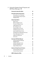
... Settings Screen 60 Boot Settings Screen 61 Integrated Devices Screen 62 PCI IRQ Assignments Screen 63 Serial Communication Screen 63 Embedded Server Management Screen 64 Power Management Screen 65 System Security Screen 66 Exit Screen 67 Entering the UEFI Boot Manager 68 Using the UEFI Boot Manager Navigation Keys 68 UEFI...
... Settings Screen 60 Boot Settings Screen 61 Integrated Devices Screen 62 PCI IRQ Assignments Screen 63 Serial Communication Screen 63 Embedded Server Management Screen 64 Power Management Screen 65 System Security Screen 66 Exit Screen 67 Entering the UEFI Boot Manager 68 Using the UEFI Boot Manager Navigation Keys 68 UEFI...

Hardware Manual
Page 5
... Hard Drive 82 Installing a Hot-Swap Hard Drive 83 Removing a Hard Drive From a Hard-Drive Carrier 84 Installing a Hard Drive Into a Hard-Drive Carrier 84 Power Supplies 86 Removing a Power Supply 86 Replacing a Power Supply 87 Removing the Power Supply Blank 88 Installing the Power Supply Blank 88 Contents 5
... Hard Drive 82 Installing a Hot-Swap Hard Drive 83 Removing a Hard Drive From a Hard-Drive Carrier 84 Installing a Hard Drive Into a Hard-Drive Carrier 84 Power Supplies 86 Removing a Power Supply 86 Replacing a Power Supply 87 Removing the Power Supply Blank 88 Installing the Power Supply Blank 88 Contents 5
Hardware Manual
Page 9
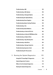
...NIC 155 Troubleshooting a Wet System 156 Troubleshooting a Damaged System 157 Troubleshooting the System Battery 158 Troubleshooting Power Supplies 158 Troubleshooting System Cooling Problems 159 Troubleshooting a Fan 160 Troubleshooting System Memory 160 Troubleshooting an ... Controller 167 Troubleshooting Expansion Cards 168 Troubleshooting the Processor(s 170 5 Running the System Diagnostics . . . . . 173 Using Dell™ PowerEdge™ Diagnostics 173 System Diagnostics Features 173 When to Use the System Diagnostics 174 Running the System Diagnostics 174 Contents 9
...NIC 155 Troubleshooting a Wet System 156 Troubleshooting a Damaged System 157 Troubleshooting the System Battery 158 Troubleshooting Power Supplies 158 Troubleshooting System Cooling Problems 159 Troubleshooting a Fan 160 Troubleshooting System Memory 160 Troubleshooting an ... Controller 167 Troubleshooting Expansion Cards 168 Troubleshooting the Processor(s 170 5 Running the System Diagnostics . . . . . 173 Using Dell™ PowerEdge™ Diagnostics 173 System Diagnostics Features 173 When to Use the System Diagnostics 174 Running the System Diagnostics 174 Contents 9
Hardware Manual
Page 13
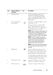
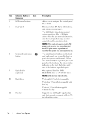
... A slide-out label panel for five seconds. Use this button only if directed to the system. About Your System 13 The power button controls the DC power supply output to do so by qualified support personnel or by the operating system's documentation. NOTE: To force an ungraceful shutdown, ... the system using certain operating systems. This button can take up to 25 seconds to the system is turned off. The power-on indicator lights when the system power is not accessible. Used to the system. Connects USB devices to troubleshoot software and device driver errors when using the...
... A slide-out label panel for five seconds. Use this button only if directed to the system. About Your System 13 The power button controls the DC power supply output to do so by qualified support personnel or by the operating system's documentation. NOTE: To force an ungraceful shutdown, ... the system using certain operating systems. This button can take up to 25 seconds to the system is turned off. The power-on indicator lights when the system power is not accessible. Used to the system. Connects USB devices to troubleshoot software and device driver errors when using the...
Hardware Manual
Page 14
... a rack. NOTE: DVD devices are data only. Up to eight 2.5-inch hot-swappable Up to four 3.5-inch hot-swappable with flex bay Up to AC power and an error has been detected, the LCD lights amber regardless of the buttons is pushed, the LCD panel on the front and the system... status indicator on the back flash blue until one of whether the system has been powered on. One optional slim-line SATA DVD-ROM drive or DVD+RW drive. NOTE: If the system is connected to six 3.5-inch hot-swappable without...
... a rack. NOTE: DVD devices are data only. Up to eight 2.5-inch hot-swappable Up to four 3.5-inch hot-swappable with flex bay Up to AC power and an error has been detected, the LCD lights amber regardless of the buttons is pushed, the LCD panel on the front and the system... status indicator on the back flash blue until one of whether the system has been powered on. One optional slim-line SATA DVD-ROM drive or DVD+RW drive. NOTE: If the system is connected to six 3.5-inch hot-swappable without...
Hardware Manual
Page 17
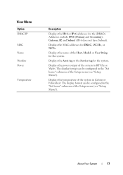
View Menu Option DRAC IP MAC Name Number Power Temperature Description Displays the IPv4 or IPv6 addresses for the system. Addresses include DNS (Primary and Secondary), Gateway, IP, and Subnet (IPv6 does not have ... can be configured in the "Set home" submenu of the system in the "Set home" submenu of the Setup menu (see "Setup Menu"). Displays the power output of the Setup menu (see "Setup Menu"). The display format can be configured in BTU/hr or Watts. Displays the MAC addresses for the...
View Menu Option DRAC IP MAC Name Number Power Temperature Description Displays the IPv4 or IPv6 addresses for the system. Addresses include DNS (Primary and Secondary), Gateway, IP, and Subnet (IPv6 does not have ... can be configured in the "Set home" submenu of the system in the "Set home" submenu of the Setup menu (see "Setup Menu"). Displays the power output of the Setup menu (see "Setup Menu"). The display format can be configured in BTU/hr or Watts. Displays the MAC addresses for the...
Hardware Manual
Page 18
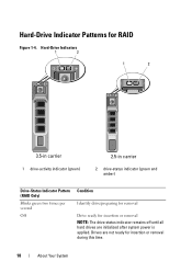
Hard-Drive Indicator Patterns for insertion or removal during this time. 18 About Your System Drives are initialized after system power is applied. Hard-Drive Indicators 1 2 1 2 3.5-in carrier 1 drive-activity indicator (green) 2.5-in carrier 2 drive-status indicator (green and amber) Drive-Status Indicator Pattern (RAID Only) Blinks green two times per second Off Condition Identify drive/preparing for removal Drive ready for insertion or removal NOTE: The drive status indicator remains off until all hard drives are not ready for RAID Figure 1-4.
Hard-Drive Indicator Patterns for insertion or removal during this time. 18 About Your System Drives are initialized after system power is applied. Hard-Drive Indicators 1 2 1 2 3.5-in carrier 1 drive-activity indicator (green) 2.5-in carrier 2 drive-status indicator (green and amber) Drive-Status Indicator Pattern (RAID Only) Blinks green two times per second Off Condition Identify drive/preparing for removal Drive ready for insertion or removal NOTE: The drive status indicator remains off until all hard drives are not ready for RAID Figure 1-4.
Hardware Manual
Page 20
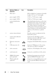
...for attaching a system indicator extension cable that is used to the system. Item Indicator, Button, or Icon Connector 4 PCIe slot 4 5 power supply 1 (PS1) 6 power supply 2 (PS2) 7 system identification button 8 system status indicator 9 system status indicator connector 10 Ethernet connectors (4) 11 USB connectors (2) ...) Description PCIe x8-link Gen 2 expansion slot (fullheight, 24.13-cm [9.5-in] length) 870-W or 570-W power supply 870-W or 570-W power supply The identification buttons on the back flash blue until one of these buttons is pushed, the LCD panel on the...
...for attaching a system indicator extension cable that is used to the system. Item Indicator, Button, or Icon Connector 4 PCIe slot 4 5 power supply 1 (PS1) 6 power supply 2 (PS2) 7 system identification button 8 system status indicator 9 system status indicator connector 10 Ethernet connectors (4) 11 USB connectors (2) ...) Description PCIe x8-link Gen 2 expansion slot (fullheight, 24.13-cm [9.5-in] length) 870-W or 570-W power supply 870-W or 570-W power supply The identification buttons on the back flash blue until one of these buttons is pushed, the LCD panel on the...
Hardware Manual
Page 21
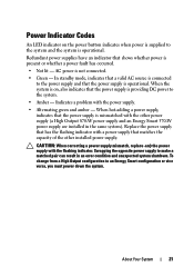
... a matched pair can result in the same system). CAUTION: When correcting a power supply mismatch, replace only the power supply with the power supply. • Alternating green and amber - Power Indicator Codes An LED indicator on , also indicates that the power supply is providing DC power to the system. • Amber - When the system is on the...
... a matched pair can result in the same system). CAUTION: When correcting a power supply mismatch, replace only the power supply with the power supply. • Alternating green and amber - Power Indicator Codes An LED indicator on , also indicates that the power supply is providing DC power to the system. • Amber - When the system is on the...
Hardware Manual
Page 22
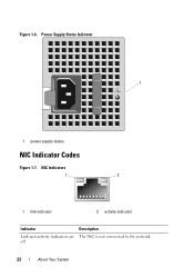
Power Supply Status Indicator 1 1 power supply status NIC Indicator Codes Figure 1-7. Figure 1-6. NIC Indicators 1 2 1 link indicator 2 activity indicator Indicator Link and activity indicators are off Description The NIC is not connected to the network. 22 About Your System
Power Supply Status Indicator 1 1 power supply status NIC Indicator Codes Figure 1-7. Figure 1-6. NIC Indicators 1 2 1 link indicator 2 activity indicator Indicator Link and activity indicators are off Description The NIC is not connected to the network. 22 About Your System
Hardware Manual
Page 23
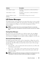
...configuring system management settings, see "Getting Help." The NIC is connected to boot, press the System ID button for the system. • Power cycle - Network data is being sent or received. Record the code, then see the systems management software documentation. Press the Select button to... to select the format in which the messages are displayed in the System Event Log (SEL). wait approximately ten seconds, reconnect the power cable, and restart the system. LCD Status Messages The LCD messages consist of errors or status messages. Removing LCD Status Messages For ...
...configuring system management settings, see "Getting Help." The NIC is connected to boot, press the System ID button for the system. • Power cycle - Network data is being sent or received. Record the code, then see the systems management software documentation. Press the Select button to... to select the format in which the messages are displayed in the System Event Log (SEL). wait approximately ten seconds, reconnect the power cable, and restart the system. LCD Status Messages The LCD messages consist of errors or status messages. Removing LCD Status Messages For ...
Hardware Manual
Page 24
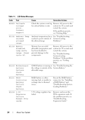
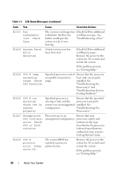
...Problems." 3.3V voltage regulator has failed. Table 1-1. E1216 3.3V Regulator failure. Cause Corrective Actions Check the system event log Remove AC power to the system for 10 seconds and restart the system. Ambient temperature has a See "Troubleshooting reached a point outside of System Cooling...Remove and reseat the PCIe expansion cards. LCD Status Messages Code Text E1000 Failsafe voltage error. Power cycle AC. E1211 RAID Controller battery failure. Remove AC power to the for 10 seconds and restart the system. If the problem persists, see "Getting Help...
...Problems." 3.3V voltage regulator has failed. Table 1-1. E1216 3.3V Regulator failure. Cause Corrective Actions Check the system event log Remove AC power to the system for 10 seconds and restart the system. Ambient temperature has a See "Troubleshooting reached a point outside of System Cooling...Remove and reseat the PCIe expansion cards. LCD Status Messages Code Text E1000 Failsafe voltage error. Power cycle AC. E1211 RAID Controller battery failure. Remove AC power to the for 10 seconds and restart the system. If the problem persists, see "Getting Help...

Hardware Manual
Page 25
... Regulator failure. If the problem persists, see "Getting Help." Specified processor VCORE voltage regulator has failed. Remove AC power to the when powering up the system for 10 seconds and restart the system. See "Troubleshooting the Processor(s)." If the problem persists, see... "Getting Help." Specified processor VTT Reseat the processor(s). Power cycle AC. Failed. Reseat DIMMs. Reseat the memory modules. Check fan. RPM of specified fan is outside of intended ...
... Regulator failure. If the problem persists, see "Getting Help." Specified processor VCORE voltage regulator has failed. Remove AC power to the when powering up the system for 10 seconds and restart the system. See "Troubleshooting the Processor(s)." If the problem persists, see... "Getting Help." Specified processor VTT Reseat the processor(s). Power cycle AC. Failed. Reseat DIMMs. Reseat the memory modules. Check fan. RPM of specified fan is outside of intended ...
Hardware Manual
Page 26
...10 seconds and restart the system. Check CPU is in your CPU configur- Remove AC power to the system for additional scrolling messages. heating. Remove AC power to the type CPU or BIOS described in an Ensure that your system's Getting Started Guide... E1418 CPU # not detected. Specified processor is Ensure that the processor exceeding acceptable temperature heat sinks are in the processor revision. Power cycle AC. Table 1-1. The system BIOS has reported a processor protocol error. See failure would put the "Troubleshooting a Fan." If...
...10 seconds and restart the system. Check CPU is in your CPU configur- Remove AC power to the system for additional scrolling messages. heating. Remove AC power to the type CPU or BIOS described in an Ensure that your system's Getting Started Guide... E1418 CPU # not detected. Specified processor is Ensure that the processor exceeding acceptable temperature heat sinks are in the processor revision. Power cycle AC. Table 1-1. The system BIOS has reported a processor protocol error. See failure would put the "Troubleshooting a Fan." If...
Hardware Manual
Page 27
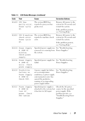
... system for 10 seconds and restart the system. Check power supply. E161C Power Supply # (### W) lost its AC input. Specified power supply is missing from Power Supplies." power supply. Remove AC power to the system, but source for the specified it has lost AC power. E1618 Predictive failure on Power Supply # (### W). If the problem persists, see "Getting Help." If...
... system for 10 seconds and restart the system. Check power supply. E161C Power Supply # (### W) lost its AC input. Specified power supply is missing from Power Supplies." power supply. Remove AC power to the system, but source for the specified it has lost AC power. E1618 Predictive failure on Power Supply # (### W). If the problem persists, see "Getting Help." If...
Hardware Manual
Page 28
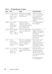
...) Code Text Cause Corrective Actions E1620 Power Supply # (### W) AC power error. E1624 Lost power supply redundancy. redundant. The system configuration requires more information and then clear the SEL. Check the SEL for more power than the power supplies can provide, even with matching ...wattage are not the same PSU1 = ### W, wattage. E1629 Power required > PSU wattage. Ensure that power supplies with throttling. The system BIOS has reported an ...
...) Code Text Cause Corrective Actions E1620 Power Supply # (### W) AC power error. E1624 Lost power supply redundancy. redundant. The system configuration requires more information and then clear the SEL. Check the SEL for more power than the power supplies can provide, even with matching ...wattage are not the same PSU1 = ### W, wattage. E1629 Power required > PSU wattage. Ensure that power supplies with throttling. The system BIOS has reported an ...
Hardware Manual
Page 29
... system, but is faulty. The system BIOS has determined there has been an error in PCI "Troubleshooting configuration space at bus ##, device ##, function ##. Remove AC power to determine its origin. E1714 Unknown error. Check the SEL for 10 seconds and restart the system. LCD Status Messages (continued) Code Text Cause Corrective...
... system, but is faulty. The system BIOS has determined there has been an error in PCI "Troubleshooting configuration space at bus ##, device ##, function ##. Remove AC power to determine its origin. E1714 Unknown error. Check the SEL for 10 seconds and restart the system. LCD Status Messages (continued) Code Text Cause Corrective...

Hardware Manual
Page 30
... has reported a chipset internal error that the specified processor has had an internal error. Remove AC power to the system for 10 seconds, and restart the system. Remove AC power to the system for more information, and then clear the SEL. LCD Status Messages (continued) Code... Text Cause Corrective Actions E1715 Fatal I/O Error. Remove AC power to the system for 10 seconds, and restart the system. E1716 Chipset IERR Bus ## Dev ## Function ##. Table 1-1. The system BIOS has ...
... has reported a chipset internal error that the specified processor has had an internal error. Remove AC power to the system for 10 seconds, and restart the system. Remove AC power to the system for more information, and then clear the SEL. LCD Status Messages (continued) Code... Text Cause Corrective Actions E1715 Fatal I/O Error. Remove AC power to the system for 10 seconds, and restart the system. E1716 Chipset IERR Bus ## Dev ## Function ##. Table 1-1. The system BIOS has ...
Hardware Manual
Page 31
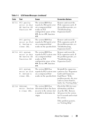
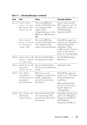
...expansion cards. reported a PCIe fatal error card riser. E1810 Hard drive ## The specified hard drive fault. E1A11 PCI Riser PCIe risers are missing. powering on Slot #. resides in PCI configuration space at bus ##, device ##, function ##. removed. Some configuration invalid configurations mismatch. If the problem persists, ...## Function ## The system BIOS has reported a PCIe fatal error on . has been removed from Reconfigure. This prevents the system from powering on a component that Cards and Expansion- See "Getting Help." Table 1-1. Review & clear SEL.
...expansion cards. reported a PCIe fatal error card riser. E1810 Hard drive ## The specified hard drive fault. E1A11 PCI Riser PCIe risers are missing. powering on Slot #. resides in PCI configuration space at bus ##, device ##, function ##. removed. Some configuration invalid configurations mismatch. If the problem persists, ...## Function ## The system BIOS has reported a PCIe fatal error on . has been removed from Reconfigure. This prevents the system from powering on a component that Cards and Expansion- See "Getting Help." Table 1-1. Review & clear SEL.


