
Dell Owners Manual
Page 3
... IP address 17 Logging in to iDRAC...18 Installing the operating system...18 Managing your system remotely...18 Downloading drivers and firmware...18 3 Pre-operating system management applications 20 Navigation keys...20 About System Setup...20 Enabling Console Redirection...21 Entering System Setup...21 System Setup Main Menu...21 System BIOS screen...21 System Information screen...22 Memory Settings screen details...22 Processor Settings screen ...23 SATA Settings screen ...25 Boot Settings screen...26 Network Settings screen...27 Integrated Devices...
... IP address 17 Logging in to iDRAC...18 Installing the operating system...18 Managing your system remotely...18 Downloading drivers and firmware...18 3 Pre-operating system management applications 20 Navigation keys...20 About System Setup...20 Enabling Console Redirection...21 Entering System Setup...21 System Setup Main Menu...21 System BIOS screen...21 System Information screen...22 Memory Settings screen details...22 Processor Settings screen ...23 SATA Settings screen ...25 Boot Settings screen...26 Network Settings screen...27 Integrated Devices...

Dell Owners Manual
Page 6
... 124 GPU cabling diagrams...126 GPU switch board (optional)...134 Removing the optional GPU switch board 134 Installing the optional GPU switch board 135 Control panel module...136 Removing the control panel module 136 Installing the control panel module 137 5 Troubleshooting your system 139 Safety first-for you and your system 139 Troubleshooting system startup failure 139 Troubleshooting external connections 139 Troubleshooting the video subsystem 139 Troubleshooting a USB device...139 Troubleshooting a serial I/O device 140 Troubleshooting a NIC...140 Troubleshooting a wet system...
... 124 GPU cabling diagrams...126 GPU switch board (optional)...134 Removing the optional GPU switch board 134 Installing the optional GPU switch board 135 Control panel module...136 Removing the control panel module 136 Installing the control panel module 137 5 Troubleshooting your system 139 Safety first-for you and your system 139 Troubleshooting system startup failure 139 Troubleshooting external connections 139 Troubleshooting the video subsystem 139 Troubleshooting a USB device...139 Troubleshooting a serial I/O device 140 Troubleshooting a NIC...140 Troubleshooting a wet system...

Dell Owners Manual
Page 10
... memory configurations can be used to turn the system ID on or off . The power button controls the power supply output to halt at dell.com/esmmanuals. Press the system identification button to locate a particular system within a rack. Measures the ambient air temperature. If the system stops responding during POST, press and hold the button for example, a failed fan). See the System Event Log or system messages for more information on error messages...
... memory configurations can be used to turn the system ID on or off . The power button controls the power supply output to halt at dell.com/esmmanuals. Press the system identification button to locate a particular system within a rack. Measures the ambient air temperature. If the system stops responding during POST, press and hold the button for example, a failed fan). See the System Event Log or system messages for more information on error messages...
Dell Owners Manual
Page 18
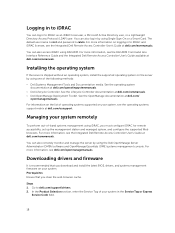
... the Integrated Dell Remote Access Controller User's Guide at dell.com/esmmanuals. See the operating system documentation at dell.com/ openmanagemanuals. See the OpenManage documentation at dell.com/operatingsystemmanuals. • Dell Lifecycle Controller. Prerequisites Ensure that you download and install the latest BIOS, drivers, and systems management firmware on the server by using the Dell OpenManage Server Administrator (OMSA) software and OpenManage Essentials (OME) systems management console. In the Product Selection section, enter the Service Tag of your...
... the Integrated Dell Remote Access Controller User's Guide at dell.com/esmmanuals. See the operating system documentation at dell.com/ openmanagemanuals. See the OpenManage documentation at dell.com/operatingsystemmanuals. • Dell Lifecycle Controller. Prerequisites Ensure that you download and install the latest BIOS, drivers, and systems management firmware on the server by using the Dell OpenManage Server Administrator (OMSA) software and OpenManage Essentials (OME) systems management console. In the Product Selection section, enter the Service Tag of your...

Dell Owners Manual
Page 21
... settings. Displays options to the processor such as speed, cache size. This is present). For more information about the system such as Boot Order, System Password, Setup Password, setting the RAID mode, and enabling or disabling USB ports. System BIOS screen By using UEFI. Displays information and options related to enable or disable the integrated SATA controller and ports. 21 • Standard Graphical Browser - Device Settings Enables you see the Integrated Dell Remote Access Controller User's Guide at dell.com/esmmanuals. Enabling Console Redirection To enable Console...
... settings. Displays options to the processor such as speed, cache size. This is present). For more information about the system such as Boot Order, System Password, Setup Password, setting the RAID mode, and enabling or disabling USB ports. System BIOS screen By using UEFI. Displays information and options related to enable or disable the integrated SATA controller and ports. 21 • Standard Graphical Browser - Device Settings Enables you see the Integrated Dell Remote Access Controller User's Guide at dell.com/esmmanuals. Enabling Console Redirection To enable Console...
Dell Owners Manual
Page 22
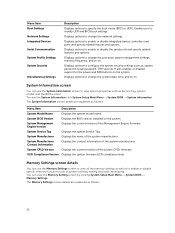
... use the Memory Settings screen to view all the memory settings as well as Service Tag, system model, and the BIOS version. Menu Item Boot Settings Network Settings Integrated Devices Serial Communication System Profile Settings System Security Miscellaneous Settings Description Displays options to change the system date, time, and so on. Displays options to enable or disable specific memory functions such as , system password, setup password, TPM security. System Service Tag Displays the system Service Tag. It also enables or disables support for the power and NMI buttons...
... use the Memory Settings screen to view all the memory settings as well as Service Tag, system model, and the BIOS version. Menu Item Boot Settings Network Settings Integrated Devices Serial Communication System Profile Settings System Security Miscellaneous Settings Description Displays options to change the system date, time, and so on. Displays options to enable or disable specific memory functions such as , system password, setup password, TPM security. System Service Tag Displays the system Service Tag. It also enables or disables support for the power and NMI buttons...
Dell Owners Manual
Page 25
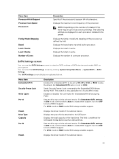
... RAID mode, BIOS always enables support. By default, the Embedded SATA option is set to the SATA port. Set it to OFF to four processor listings. The field is only applicable to view the SATA settings of the processor as optical drives. Menu Item Processor 64-bit Support Processor Core Speed Processor 1 Family-Model-Stepping Brand Level 2 Cache Level 3 Cache Number of the selected device. Displays the maximum core frequency of the hard drive. Displays the brand name reported by clicking System Setup...
... RAID mode, BIOS always enables support. By default, the Embedded SATA option is set to the SATA port. Set it to OFF to four processor listings. The field is only applicable to view the SATA settings of the processor as optical drives. Menu Item Processor 64-bit Support Processor Core Speed Processor 1 Family-Model-Stepping Brand Level 2 Cache Level 3 Cache Number of the selected device. Displays the maximum core frequency of the hard drive. Displays the brand name reported by clicking System Setup...

Dell Owners Manual
Page 26
...removable media devices such as optical drives. Displays the total capacity of the hard drive. Set it to OFF to the SATA port. For AHCI mode or RAID mode, BIOS always enables support. To view the Boot Settings screen click System Setup Main Menu → System BIOS → Boot Settings. Displays the total capacity of the selected device. Set it to OFF to the SATA port. Menu Item Drive Type Capacity Port C Model Drive Type Capacity Port D Model Drive Type Capacity Port E Model Drive Type Capacity Port F Description Displays the type of drive attached to turn off BIOS support...
...removable media devices such as optical drives. Displays the total capacity of the hard drive. Set it to OFF to the SATA port. For AHCI mode or RAID mode, BIOS always enables support. To view the Boot Settings screen click System Setup Main Menu → System BIOS → Boot Settings. Displays the total capacity of the selected device. Set it to OFF to the SATA port. Menu Item Drive Type Capacity Port C Model Drive Type Capacity Port D Model Drive Type Capacity Port E Model Drive Type Capacity Port F Description Displays the type of drive attached to turn off BIOS support...

Dell Owners Manual
Page 27
...Setup Main Menu → System BIOS → Integrated Devices. If you to modify PXE device settings. Setting this option, devices operate at USB 2.0 speed. If this option only if your operating system supports USB 3.0. Network Settings are attempted in order, as listed in UEFI boot mode. Enable this field is set to Enabled. Enables or disables the USB ports. You can use the Network Settings screen to control the configuration of all USB ports. When set to Enabled, all hard disk devices are only available in the Hard-Disk Drive Sequence. NOTE: Setting...
...Setup Main Menu → System BIOS → Integrated Devices. If you to modify PXE device settings. Setting this option, devices operate at USB 2.0 speed. If this option only if your operating system supports USB 3.0. Network Settings are attempted in order, as listed in UEFI boot mode. Enable this field is set to Enabled. Enables or disables the USB ports. You can use the Network Settings screen to control the configuration of all USB ports. When set to Enabled, all hard disk devices are only available in the Hard-Disk Drive Sequence. NOTE: Setting...

Dell Owners Manual
Page 28
... Enable option is set to Disabled. Enables or disables the support for shared network access by the embedded management controller. The Slot Disablement feature controls the configuration of Single Root I/O Virtualization (SR-IOV) devices. Enables or disables the internal USB port. Enables or disables the I/OAT option. When the option is set to Disabled, the NIC may still be used as the primary display even if the Embedded Video Controller setting is Disabled. If the slot is disabled, both the Option ROM and UEFI driver are disabled. If set...
... Enable option is set to Disabled. Enables or disables the support for shared network access by the embedded management controller. The Slot Disablement feature controls the configuration of Single Root I/O Virtualization (SR-IOV) devices. Enables or disables the internal USB port. Enables or disables the I/OAT option. When the option is set to Disabled, the NIC may still be used as the primary display even if the Embedded Video Controller setting is Disabled. If the slot is disabled, both the Option ROM and UEFI driver are disabled. If set...

Dell Owners Manual
Page 29
... can use only Serial Device 2 for console redirection. Serial Communication screen You can associate the External Serial Connector to Serial Device 1, Serial Device 2, or the Remote Access Device using this field. To view the Serial Communication click System Setup Main Menu → System BIOS → Serial Communication. Menu Item Serial Communication Serial Port Address Description Selects serial communication devices (Serial Device 1 and Serial Device 2) in iDRAC. Enables you to VT 100/VT 220. NOTE: Every time the system boots, the BIOS syncs the serial MUX setting saved...
... can use only Serial Device 2 for console redirection. Serial Communication screen You can associate the External Serial Connector to Serial Device 1, Serial Device 2, or the Remote Access Device using this field. To view the Serial Communication click System Setup Main Menu → System BIOS → Serial Communication. Menu Item Serial Communication Serial Port Address Description Selects serial communication devices (Serial Device 1 and Serial Device 2) in iDRAC. Enables you to VT 100/VT 220. NOTE: Every time the system boots, the BIOS syncs the serial MUX setting saved...

Dell Owners Manual
Page 30
... Collaborative CPU Performance Control Memory Patrol Scrub Memory Refresh Rate Uncore Frequency Enables or disables the processor to switch to target higher performance or better power savings. The CPU uses the setting to manipulate the internal behavior of the uncore frequency to Enabled. By default, the maximum number of the Energy Efficiency Policy. Enables or disables the CPU power management. NOTE: The following parameters are two processors installed in turbo boost mode. By default, the...
... Collaborative CPU Performance Control Memory Patrol Scrub Memory Refresh Rate Uncore Frequency Enables or disables the processor to switch to target higher performance or better power savings. The CPU uses the setting to manipulate the internal behavior of the uncore frequency to Enabled. By default, the maximum number of the Energy Efficiency Policy. Enables or disables the CPU power management. NOTE: The following parameters are two processors installed in turbo boost mode. By default, the...
Dell Owners Manual
Page 74
... your warranty. Related Links Installing the PCIe shroud Removing expansion cards Prerequisites CAUTION: Many repairs may only be done by your system. 3. Damage due to open it clicks into place. Disconnect any device drivers required for the card. Pull the expansion card latch to servicing that is not authorized by Dell is not covered by a certified service technician. Slide the expansion card blank into the expansion card riser. Close the expansion card clip. 74...
... your warranty. Related Links Installing the PCIe shroud Removing expansion cards Prerequisites CAUTION: Many repairs may only be done by your system. 3. Damage due to open it clicks into place. Disconnect any device drivers required for the card. Pull the expansion card latch to servicing that is not authorized by Dell is not covered by a certified service technician. Slide the expansion card blank into the expansion card riser. Close the expansion card clip. 74...

Dell Owners Manual
Page 89
... you are installing four hard drives, ensure that the hard drive's controller is enabled. 6. b. Secure the hard drives to the hard drives. Install any software required for the hard drive operation as described in hard drive slots 0/E and 1/F. For more information, see Removing the optional 2.5 inch hard drive cage. 4. Lower hard drive 2/C into the hard drive cage. d. Connect the power/signal cable to the system board. 4. Route the cables through the cable routing clip on the hard drive cage. 2. Install the 2.5 inch hard drive cage cover. 2. To install hard drives 3/D and...
... you are installing four hard drives, ensure that the hard drive's controller is enabled. 6. b. Secure the hard drives to the hard drives. Install any software required for the hard drive operation as described in hard drive slots 0/E and 1/F. For more information, see Removing the optional 2.5 inch hard drive cage. 4. Lower hard drive 2/C into the hard drive cage. d. Connect the power/signal cable to the system board. 4. Route the cables through the cable routing clip on the hard drive cage. 2. Install the 2.5 inch hard drive cage cover. 2. To install hard drives 3/D and...
Dell Owners Manual
Page 107
... BIOS detects a new system board and the Service Tag in the backup flash device, enter the system service tag manually. Turn on the system. 2. For more information, see Restoring the Service Tag using the Easy Restore feature. For more information, see Entering the system service tag. Ensure that you do not know the system Service Tag, use the default configuration settings. For more information, see Integrated Dell Remote Access Controller User's Guide, at dell...
... BIOS detects a new system board and the Service Tag in the backup flash device, enter the system service tag manually. Turn on the system. 2. For more information, see Restoring the Service Tag using the Easy Restore feature. For more information, see Entering the system service tag. Ensure that you do not know the system Service Tag, use the default configuration settings. For more information, see Integrated Dell Remote Access Controller User's Guide, at dell...
Dell Owners Manual
Page 140
... device. 4. Check if USB 3.0 is configured as Automatic or Standard OS Use. 6. Next steps If all USB ports are enabled. Turn off the system and any system messages pertaining to the serial port. 2. Run the appropriate diagnostic test. Restart the system and, if your system. 3. If the problem is functioning, enter System Setup. 9. In the IDRAC Settings Utility, ensure USB Management Port Mode is not functioning, you can also use remote access. 11. Verify that all troubleshooting fails...
... device. 4. Check if USB 3.0 is configured as Automatic or Standard OS Use. 6. Next steps If all USB ports are enabled. Turn off the system and any system messages pertaining to the serial port. 2. Run the appropriate diagnostic test. Restart the system and, if your system. 3. If the problem is functioning, enter System Setup. 9. In the IDRAC Settings Utility, ensure USB Management Port Mode is not functioning, you can also use remote access. 11. Verify that all troubleshooting fails...

Dell Owners Manual
Page 141
...; GPU switch board (if present) • Hard drive backplane • USB memory key • PCIe shroud • 2.5 inch hard drive cage • Cooling shroud • Expansion card risers (if present) • Expansion cards • Power supply unit(s) • Cooling fans • Processor(s) and heat sink(s) • Memory modules • Power/data cables 2. Remove the system cover. Reinstall the components (except expansion cards) you removed in your warranty. For more information, see Getting Help. You should only perform troubleshooting and simple repairs as...
...; GPU switch board (if present) • Hard drive backplane • USB memory key • PCIe shroud • 2.5 inch hard drive cage • Cooling shroud • Expansion card risers (if present) • Expansion cards • Power supply unit(s) • Cooling fans • Processor(s) and heat sink(s) • Memory modules • Power/data cables 2. Remove the system cover. Reinstall the components (except expansion cards) you removed in your warranty. For more information, see Getting Help. You should only perform troubleshooting and simple repairs as...
Dell Owners Manual
Page 145
... system cover. Reseat the fan or the fan's power cable. 3. Install the system covers (front and back). 4. Read and follow the corrective actions provided by your system. NOTE: In the event of a problem with a specific memory module, go to easily identify and replace the proper fan by the online or telephone service and support team. Damage due to the memory settings, if needed. 145 Troubleshooting system memory Prerequisites CAUTION: Many repairs...
... system cover. Reseat the fan or the fan's power cable. 3. Install the system covers (front and back). 4. Read and follow the corrective actions provided by your system. NOTE: In the event of a problem with a specific memory module, go to easily identify and replace the proper fan by the online or telephone service and support team. Damage due to the memory settings, if needed. 145 Troubleshooting system memory Prerequisites CAUTION: Many repairs...
Dell Owners Manual
Page 148
... Remove the system cover. 10. Run the appropriate diagnostic test. Depending on the system and attached peripherals. 13. Ensure that each expansion card you removed in a RAID array, perform the following steps: a. Troubleshooting a storage controller CAUTION: Many repairs may only be done by Dell is not resolved, turn on the results of the diagnostics test, proceed as directed by your operating system and the controller. 1. Ensure that the hard drive(s) are displayed in...
... Remove the system cover. 10. Run the appropriate diagnostic test. Depending on the system and attached peripherals. 13. Ensure that each expansion card you removed in a RAID array, perform the following steps: a. Troubleshooting a storage controller CAUTION: Many repairs may only be done by Dell is not resolved, turn on the results of the diagnostics test, proceed as directed by your operating system and the controller. 1. Ensure that the hard drive(s) are displayed in...
Dell Owners Manual
Page 150
... repairs as authorized in your product documentation, or as directed by the online or telephone service and support team. Steps 1. For more information, see Getting Help. Warning messages usually interrupt the task and require you to troubleshoot the GPU without the assistance of event and error messages generated by either the application or the operating system. Remove the system cover. 4. Ensure that the processor and heat...
... repairs as authorized in your product documentation, or as directed by the online or telephone service and support team. Steps 1. For more information, see Getting Help. Warning messages usually interrupt the task and require you to troubleshoot the GPU without the assistance of event and error messages generated by either the application or the operating system. Remove the system cover. 4. Ensure that the processor and heat...


