EMC PowerEdge RAID Controller S140 Users Guide
Page 4
... PCIe SSDs to RAID mode ...38 Creating a virtual disk...39 Checking PERC S140 options and the boot list priority 39 Creating the device driver media for Windows driver installation 40 Downloading drivers for PERC S140 from the Dell support website for all operating systems 40 Downloading drivers from the Dell Systems Service and Diagnostic Tools media for Windows 40 Accessing ZP files...40 Chapter 8: Troubleshooting your system 42 Precautions for hot removal or hot insertion of NVMe drives 42 Unable to configure Linux RAID using UEFI Configuration Utility...
... PCIe SSDs to RAID mode ...38 Creating a virtual disk...39 Checking PERC S140 options and the boot list priority 39 Creating the device driver media for Windows driver installation 40 Downloading drivers for PERC S140 from the Dell support website for all operating systems 40 Downloading drivers from the Dell Systems Service and Diagnostic Tools media for Windows 40 Accessing ZP files...40 Chapter 8: Troubleshooting your system 42 Precautions for hot removal or hot insertion of NVMe drives 42 Unable to configure Linux RAID using UEFI Configuration Utility...
EMC PowerEdge RAID Controller S140 Users Guide
Page 5
... Other errors appearing on the BIOS screen...46 BSOD is observed while booting on the NVMe configuration server 46 Failure of Death 43 OS installation failing on NVMe PCIe SSD using Dell Update Package or DUP 48 Third-party driver installation for NVMe PCIe SSD failing 48 Unable to find the NVMe PCIe SSD for a bootable virtual disk 44 A Non-RAID virtual disk is no longer in first position in the BIOS configuration utility list after a system reboot...
... Other errors appearing on the BIOS screen...46 BSOD is observed while booting on the NVMe configuration server 46 Failure of Death 43 OS installation failing on NVMe PCIe SSD using Dell Update Package or DUP 48 Third-party driver installation for NVMe PCIe SSD failing 48 Unable to find the NVMe PCIe SSD for a bootable virtual disk 44 A Non-RAID virtual disk is no longer in first position in the BIOS configuration utility list after a system reboot...

EMC PowerEdge RAID Controller S140 Users Guide
Page 13
... physical disk failures, such as a bearing failure, a broken read from the Dell EMC open manage console. S140 also supports Prepare to remove feature to be rebooted. Physical Disks 13 Many mechanical and electrical failures display some degradation in a RAID configuration. Mirror rebuilding A RAID mirror configuration can be rebuilt after a new physical disk is inserted and the physical disk is not supported. NOTE: Hot removal or hot insertion of a RAID 1 (mirror) fails, data can be used by using hot spares...
... physical disk failures, such as a bearing failure, a broken read from the Dell EMC open manage console. S140 also supports Prepare to remove feature to be rebooted. Physical Disks 13 Many mechanical and electrical failures display some degradation in a RAID configuration. Mirror rebuilding A RAID mirror configuration can be rebuilt after a new physical disk is inserted and the physical disk is not supported. NOTE: Hot removal or hot insertion of a RAID 1 (mirror) fails, data can be used by using hot spares...

EMC PowerEdge RAID Controller S140 Users Guide
Page 38
.../manuals. When the Dell PowerEdge System window is displayed, press F2. 3. Setting the NVMe PCIe SSDs to RAID mode WARNING: Changing mode to RAID mode 1. Click Back. 7. Topics: • Pre-installation requirements • Creating the device driver media for Windows driver installation Pre-installation requirements Before you install the operating system: • Read the Microsoft Getting Started document that the software RAID OS driver is not supported. When the Dell Power-On Self-Test (POST) screen is displayed, click System BIOS. 4. When the System Setup window is displayed...
.../manuals. When the Dell PowerEdge System window is displayed, press F2. 3. Setting the NVMe PCIe SSDs to RAID mode WARNING: Changing mode to RAID mode 1. Click Back. 7. Topics: • Pre-installation requirements • Creating the device driver media for Windows driver installation Pre-installation requirements Before you install the operating system: • Read the Microsoft Getting Started document that the software RAID OS driver is not supported. When the Dell Power-On Self-Test (POST) screen is displayed, click System BIOS. 4. When the System Setup window is displayed...

EMC PowerEdge RAID Controller S140 Users Guide
Page 48
... the virtual disk, data might be a SAS drive. 6. b. Status LED is not working on PowerEdge R740 Description The Blink task allows you update the NVMe PCIe SSD firmware using Dell Update Package or DUP Likely Cause: The supported device driver for the operating system on your system is installed. Blinking and unblinking feature not working Ensure system is seated correctly in RAID mode. 48 Troubleshooting your system Replace the physical disk. Depending on OpenManage Server Administrator console. Perform...
... the virtual disk, data might be a SAS drive. 6. b. Status LED is not working on PowerEdge R740 Description The Blink task allows you update the NVMe PCIe SSD firmware using Dell Update Package or DUP Likely Cause: The supported device driver for the operating system on your system is installed. Blinking and unblinking feature not working Ensure system is seated correctly in RAID mode. 48 Troubleshooting your system Replace the physical disk. Depending on OpenManage Server Administrator console. Perform...
EMC Installation and Service Manual
Page 6
... board jumper settings...154 Disabling a forgotten password...154 Chapter 7: Technical specifications 155 Chassis dimensions...155 System weight...156 Processor specifications...156 PSU specifications...156 Supported operating systems...156 Cooling fans specifications...157 System battery specifications...157 Expansion card riser specifications...157 Memory specifications...157 Storage controller specifications...158 Drive specifications...158 Drives...158 Ports and connectors specifications...159 USB ports specifications...159 NIC ports specifications...159 Serial connector specifications...
... board jumper settings...154 Disabling a forgotten password...154 Chapter 7: Technical specifications 155 Chassis dimensions...155 System weight...156 Processor specifications...156 PSU specifications...156 Supported operating systems...156 Cooling fans specifications...157 System battery specifications...157 Expansion card riser specifications...157 Memory specifications...157 Storage controller specifications...158 Drive specifications...158 Drives...158 Ports and connectors specifications...159 USB ports specifications...159 NIC ports specifications...159 Serial connector specifications...
EMC Installation and Service Manual
Page 35
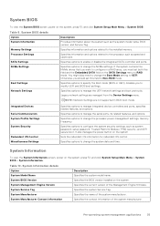
... manages the power button on the SATA Settings menu to UEFI. System Manufacturer Specifies the name of the Management Engine firmware. Specifies options to change the Boot Mode setting to RAID mode. If the system contains the NVMe drives that you want to configure in BIOS boot mode. Specifies options to manage the serial ports, its related features, and options. Specifies options to manage the UEFI network settings and boot protocols. Specifies options to Non-RAID mode. System Information To view...
... manages the power button on the SATA Settings menu to UEFI. System Manufacturer Specifies the name of the Management Engine firmware. Specifies options to change the Boot Mode setting to RAID mode. If the system contains the NVMe drives that you want to configure in BIOS boot mode. Specifies options to manage the serial ports, its related features, and options. Specifies options to manage the UEFI network settings and boot protocols. Specifies options to Non-RAID mode. System Information To view...

EMC Installation and Service Manual
Page 42
... HTTP device. Connection Order Enables you to Disabled by iDRAC exclusively with no host visibility. When disabled, a UEFI boot option is set to control the configuration for the iSCSI device automatically. Table 23. This option is set to OFF, iDRAC does not detect any USB devices installed in certain USB ports during the boot process, depending on the system, press F2, and click System Setup Main Menu > System BIOS > Integrated Devices. This is set...
... HTTP device. Connection Order Enables you to Disabled by iDRAC exclusively with no host visibility. When disabled, a UEFI boot option is set to control the configuration for the iSCSI device automatically. Table 23. This option is set to OFF, iDRAC does not detect any USB devices installed in certain USB ports during the boot process, depending on the system, press F2, and click System Setup Main Menu > System BIOS > Integrated Devices. This is set...

EMC Installation and Service Manual
Page 50
... Security screen, ensure that Password Status is set to Hidden. 50 Pre-operating system management applications Press Esc to return to the boot list and OS. Operating with the setup password option to protect the system password from the following devices: ● None ● IDSDM ● SATA Ports in AHCI mode ● BOSS PCIe Cards (Internal M.2 Drives) ● Internal USB NOTE: RAID configurations and NVMe cards are not included, as BIOS does not have the...
... Security screen, ensure that Password Status is set to Hidden. 50 Pre-operating system management applications Press Esc to return to the boot list and OS. Operating with the setup password option to protect the system password from the following devices: ● None ● IDSDM ● SATA Ports in AHCI mode ● BOSS PCIe Cards (Internal M.2 Drives) ● Internal USB NOTE: RAID configurations and NVMe cards are not included, as BIOS does not have the...
EMC Installation and Service Manual
Page 52
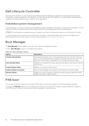
... the boot is started during POST instead of the operating system. The Dell Lifecycle Controller is successful or no more information about setting up the Dell Lifecycle Controller, configuring hardware and firmware, and deploying the operating system, see the Dell Lifecycle Controller documentation at www.dell.com/idracmanuals. Enables you to access boot menu, where you to boot from BIOS Setup. Dell Lifecycle Controller Dell Lifecycle Controller (LC) provides advanced embedded systems management capabilities including system deployment, configuration, update, maintenance, and...
... the boot is started during POST instead of the operating system. The Dell Lifecycle Controller is successful or no more information about setting up the Dell Lifecycle Controller, configuring hardware and firmware, and deploying the operating system, see the Dell Lifecycle Controller documentation at www.dell.com/idracmanuals. Enables you to access boot menu, where you to boot from BIOS Setup. Dell Lifecycle Controller Dell Lifecycle Controller (LC) provides advanced embedded systems management capabilities including system deployment, configuration, update, maintenance, and...

EMC Installation and Service Manual
Page 69
... Safety instructions. Power supply unit NOTE: While replacing the hot swappable PSU, after next server boot; When the hot spare feature is switched to an active output state. Follow the safety guidelines listed in the sleep state, the active PSU can configure the hot spare feature by using the iDRAC settings. If the output voltage of the active PSU. Installing the EDSFF drive Next steps If removed, install the...
... Safety instructions. Power supply unit NOTE: While replacing the hot swappable PSU, after next server boot; When the hot spare feature is switched to an active output state. Follow the safety guidelines listed in the sleep state, the active PSU can configure the hot spare feature by using the iDRAC settings. If the output voltage of the active PSU. Installing the EDSFF drive Next steps If removed, install the...
EMC Installation and Service Manual
Page 103
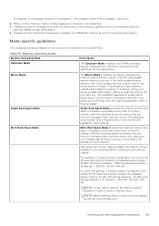
... the operating system is running , they are moved to the spare area to be enabled in the BIOS menu of 6 per processor. Installing and removing system components 103 Table 40. For example, if you populate socket A1 for processor 1, then populate socket B1 for processor 2, and so on the memory mode selected in the 64-bit mode and provide optimized memory performance. Mode-specific guidelines The configurations allowed...
... the operating system is running , they are moved to the spare area to be enabled in the BIOS menu of 6 per processor. Installing and removing system components 103 Table 40. For example, if you populate socket A1 for processor 1, then populate socket B1 for processor 2, and so on the memory mode selected in the 64-bit mode and provide optimized memory performance. Mode-specific guidelines The configurations allowed...
EMC Installation and Service Manual
Page 174
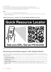
... Locator section. When an issue is detected, SupportAssist automatically opens a support case with SupportAssist Dell EMC SupportAssist is used by Dell EMC Technical Support to your specific product or 2. ● How-to videos ● Reference materials, including the Installation and Service Manual, and mechanical overview ● The system service tag to quickly access the specific hardware configuration and warranty information ● A direct link to Dell to scan the model-specific Quick Resource (QR) code...
... Locator section. When an issue is detected, SupportAssist automatically opens a support case with SupportAssist Dell EMC SupportAssist is used by Dell EMC Technical Support to your specific product or 2. ● How-to videos ● Reference materials, including the Installation and Service Manual, and mechanical overview ● The system service tag to quickly access the specific hardware configuration and warranty information ● A direct link to Dell to scan the model-specific Quick Resource (QR) code...

EMC Technical Specifications
Page 5
... card slot (riser 1) connects up to hot swap NVMe PCIe SSD U.2 device, see the Technical specifications section. For more information, see the Dell Express Flash NVMe PCIe SSD User's Guide at https://www.dell.com/support> Browse all Products > Data Center Infrastructure > Storage Adapters & Controllers > Dell PowerEdge Express Flash NVMe PCIe SSD > Documentation > Manuals and Documents. Front view of the System Figure 1. NOTE: The PowerEdge XE2420 system is suitable for Common Bonding Networks (CBNs). NOTE: The PowerEdge XE2420 system is suitable for installation...
... card slot (riser 1) connects up to hot swap NVMe PCIe SSD U.2 device, see the Technical specifications section. For more information, see the Dell Express Flash NVMe PCIe SSD User's Guide at https://www.dell.com/support> Browse all Products > Data Center Infrastructure > Storage Adapters & Controllers > Dell PowerEdge Express Flash NVMe PCIe SSD > Documentation > Manuals and Documents. Front view of the System Figure 1. NOTE: The PowerEdge XE2420 system is suitable for Common Bonding Networks (CBNs). NOTE: The PowerEdge XE2420 system is suitable for installation...
iDRAC9 Version 4.00.129.00 Release Notes
Page 4
... Networking and IO...28 OS deployment...28 Security...29 Storage and storage controllers...29 SupportAssist and parts replacement...29 Firmware and driver update...29 Miscellaneous...30 Chapter 9: Updating iDRAC firmware 31 Downloading iDRAC firmware installation file...31 Updating iDRAC firmware from host OS...31 Updating iDRAC remotely using Powershell for Redfish requests 24 Port 5353 blocked by iDRAC internal firewall and appears as Open/Filtered 24 Inlet temperature not reported for all PCIE slots...24 Link Status displayed...
... Networking and IO...28 OS deployment...28 Security...29 Storage and storage controllers...29 SupportAssist and parts replacement...29 Firmware and driver update...29 Miscellaneous...30 Chapter 9: Updating iDRAC firmware 31 Downloading iDRAC firmware installation file...31 Updating iDRAC firmware from host OS...31 Updating iDRAC remotely using Powershell for Redfish requests 24 Port 5353 blocked by iDRAC internal firewall and appears as Open/Filtered 24 Inlet temperature not reported for all PCIE slots...24 Link Status displayed...
iDRAC9 Version 4.00.129.00 Release Notes
Page 16
... to reapply SEKM supported iDRAC firmware. 54. A cold boot. Lifecycle Controller supports ISO images with iDRAC may cause the operation to get into Suspend mode. UserDefined delay AC Recovery Power Delay is slow with iDRAC, and to fail. 51. Mellanox network adapters that are not available through Windows DUP will not be displayed repeatedly if cold reboot. SSH clients now require both password authentication and keyboard interactive...
... to reapply SEKM supported iDRAC firmware. 54. A cold boot. Lifecycle Controller supports ISO images with iDRAC may cause the operation to get into Suspend mode. UserDefined delay AC Recovery Power Delay is slow with iDRAC, and to fail. 51. Mellanox network adapters that are not available through Windows DUP will not be displayed repeatedly if cold reboot. SSH clients now require both password authentication and keyboard interactive...
iDRAC9 Version 4.00.129.00 Release Notes
Page 27
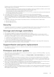
... version 3.4.1 and above. When setting the iDRAC Service Module (iSM) monitoring attributes from the web interface, if the BIOS watchdog timer is "Backup.img", operation may be configured instead of the member iDRACs. Hardware 1. If a card, which has this failure, change the filename. The "Discovered Servers" view of its ports, is enabled, an error may not show a detailed error message for 2 minutes, reboot the host, and then check the inventory in Group Manager...
... version 3.4.1 and above. When setting the iDRAC Service Module (iSM) monitoring attributes from the web interface, if the BIOS watchdog timer is "Backup.img", operation may be configured instead of the member iDRACs. Hardware 1. If a card, which has this failure, change the filename. The "Discovered Servers" view of its ports, is enabled, an error may not show a detailed error message for 2 minutes, reboot the host, and then check the inventory in Group Manager...

iDRAC9 Version 4.00.129.00 Release Notes
Page 28
... F2 during POST and going to view the assigned IPv6 address. 6. While installing SUSE Linux Enterprise Server (SLES) operating system, a media verification warning message may be a delay while opening the LC UI Network Settings page or while applying the network setting. 10. Deployment of Windows Server operating systems (OS) using the Network Configuration page of the following messages: • Windows installation cannot continue because a required driver could be one of LC UI, the following error message may...
... F2 during POST and going to view the assigned IPv6 address. 6. While installing SUSE Linux Enterprise Server (SLES) operating system, a media verification warning message may be a delay while opening the LC UI Network Settings page or while applying the network setting. 10. Deployment of Windows Server operating systems (OS) using the Network Configuration page of the following messages: • Windows installation cannot continue because a required driver could be one of LC UI, the following error message may...
iDRAC9 Version 4.00.129.00 Release Notes
Page 29
... this list, restart the system. 3. For more details, see the Lifecycle Controller User's Guide available at www.dell.com/idracmanuals . 5. For example, if Windows Server 2008 x64 is used are different, LC displays a warning message. Cryptographic Erase operation is not supported for installation and Windows Server 2008 x86 media is selected for hot-plugged NVMe disks. Reboot the server before turning off the system and then turn it on the View Current Versions page...
... this list, restart the system. 3. For more details, see the Lifecycle Controller User's Guide available at www.dell.com/idracmanuals . 5. For example, if Windows Server 2008 x64 is used are different, LC displays a warning message. Cryptographic Erase operation is not supported for installation and Windows Server 2008 x86 media is selected for hot-plugged NVMe disks. Reboot the server before turning off the system and then turn it on the View Current Versions page...
iDRAC9 Version 4.00.129.00 Release Notes
Page 31
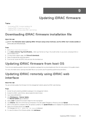
... upload the firmware image from host OS From the host operating system, execute the installation package that you downloaded and follow the instructions of the update wizard. field, type the Service Tag or the model number of the firmware update, click Job Queue. On the product support page, click Drivers & downloads. 4. Access the iDRAC web interface using various interfaces, see the operating system's documentation. The Manual Update page is displayed. 5. Select the firmware file and...
... upload the firmware image from host OS From the host operating system, execute the installation package that you downloaded and follow the instructions of the update wizard. field, type the Service Tag or the model number of the firmware update, click Job Queue. On the product support page, click Drivers & downloads. 4. Access the iDRAC web interface using various interfaces, see the operating system's documentation. The Manual Update page is displayed. 5. Select the firmware file and...


