
Hardware Owner's Manual
Page 47
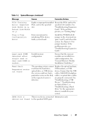
... Figure 6-1 for the appropriate drive(s) installed in the specified specified slot number. See "General Memory Module Installation Guidelines." Table 1-2. If the problem persists, see "Getting Help." "Troubleshooting a USB Device", "Troubleshooting an Optical Drive", or "Troubleshooting a Hard Drive" for jumper location. System ... after configuration. device not found The operating system cannot Replace the optical medium, read from the hard drive, USB medium, or USB optical drive, or USB device, device. Ensure that the USB the system could not find a cables, ...
... Figure 6-1 for the appropriate drive(s) installed in the specified specified slot number. See "General Memory Module Installation Guidelines." Table 1-2. If the problem persists, see "Getting Help." "Troubleshooting a USB Device", "Troubleshooting an Optical Drive", or "Troubleshooting a Hard Drive" for jumper location. System ... after configuration. device not found The operating system cannot Replace the optical medium, read from the hard drive, USB medium, or USB optical drive, or USB device, device. Ensure that the USB the system could not find a cables, ...
Hardware Owner's Manual
Page 63
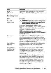
Floppy allows the USB flash drive to act as a hard drive. Hard disk allows the USB flash drive to SATA port B. Determines the emulation type for the device. Auto automatically chooses the appropriate emulation type for the device, except for devices installed in the internal SD card slot will attempt to boot from booting if the operating...
Floppy allows the USB flash drive to act as a hard drive. Hard disk allows the USB flash drive to SATA port B. Determines the emulation type for the device. Auto automatically chooses the appropriate emulation type for the device, except for devices installed in the internal SD card slot will attempt to boot from booting if the operating...
Hardware Owner's Manual
Page 79
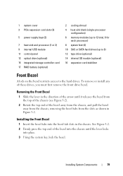
...slots (5) 5 power supply bays (2) 7 heat sink and processor (1 or 2) 9 internal USB module 11 control panel 13 optical drive (optional) 15 integrated storage controller card 17 RAID battery (optional) 2 cooling shroud 4 heat sink blank (single-processor configuration) 6 memory modules (up to 12 total, 6 for each processor) 8 system feet (4) 10 SAS or SATA hard drives... (up to 8) 12 tape drive (optional) 14 internal SD module (optional) 16 expansion card stabilizer Front Bezel A lock on the bezel restricts...
...slots (5) 5 power supply bays (2) 7 heat sink and processor (1 or 2) 9 internal USB module 11 control panel 13 optical drive (optional) 15 integrated storage controller card 17 RAID battery (optional) 2 cooling shroud 4 heat sink blank (single-processor configuration) 6 memory modules (up to 12 total, 6 for each processor) 8 system feet (4) 10 SAS or SATA hard drives... (up to 8) 12 tape drive (optional) 14 internal SD module (optional) 16 expansion card stabilizer Front Bezel A lock on the bezel restricts...
Hardware Owner's Manual
Page 80
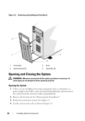
... Installing the Front Bezel 2 1 3 1 front bezel 3 bezel tab slots (2) 4 2 lever 4 bezel tabs (2) Opening and Closing the System WARNING: Whenever you need to lift the system, get others to lift the system by yourself. See Figure 3-3. 4 Lay the system on its side as a hard drive or power supply, turn off the system and attached...
... Installing the Front Bezel 2 1 3 1 front bezel 3 bezel tab slots (2) 4 2 lever 4 bezel tabs (2) Opening and Closing the System WARNING: Whenever you need to lift the system, get others to lift the system by yourself. See Figure 3-3. 4 Lay the system on its side as a hard drive or power supply, turn off the system and attached...
Hardware Owner's Manual
Page 82
...slots in the system chassis. c Press the latch end of the cover, opposite from the cover release latch, into the chassis. Hard Drives Depending on your chassis and backplane, your system while the drive is configured correctly to support hot-swap drive removal and insertion. All drives are supplied in special hotswappable hard-drive...board through the SAS backplane. Hard drives are installed at the front of the following configurations: • Eight 2.5-inch drive bays • Eight 3.5-inch drive bays All chassis support hot-swappable SAS and SATA hard drives, and the 2.5inch-bay ...
...slots in the system chassis. c Press the latch end of the cover, opposite from the cover release latch, into the chassis. Hard Drives Depending on your chassis and backplane, your system while the drive is configured correctly to support hot-swap drive removal and insertion. All drives are supplied in special hotswappable hard-drive...board through the SAS backplane. Hard drives are installed at the front of the following configurations: • Eight 2.5-inch drive bays • Eight 3.5-inch drive bays All chassis support hot-swappable SAS and SATA hard drives, and the 2.5inch-bay ...
Hardware Owner's Manual
Page 83
..., all SATA drives. Be aware that have drive blanks installed. 1 Remove the front bezel. Mixed 2.5-inch and 3.5-inch configurations of SAS and SATA drives are allowed. In this configuration, two 10,000RPM 2.5-inch SAS drives installed in 3.5-inch adapters must be either all SAS or all empty hard-drive bays must be installed in hard-drive slots 0 and 1 only...
..., all SATA drives. Be aware that have drive blanks installed. 1 Remove the front bezel. Mixed 2.5-inch and 3.5-inch configurations of SAS and SATA drives are allowed. In this configuration, two 10,000RPM 2.5-inch SAS drives installed in 3.5-inch adapters must be either all SAS or all empty hard-drive bays must be installed in hard-drive slots 0 and 1 only...
Hardware Owner's Manual
Page 112
... cables from the storage card. a Pull and hold the blue card guide away from upper corner of the storage controller included with your system's internal hard drives. Removing an Integrated Storage Controller Card 1 Turn off the system, including any peripherals, then connect the system to the electrical outlet. 17 Turn on the... card stabilizer. See "Closing the System." 15 Place the system upright and on its feet on the card. 5 Remove the card from the storage-card slot. • If you to set up the hard drives in the drive kit from the SCSI controller expansion card to the...
... cables from the storage card. a Pull and hold the blue card guide away from upper corner of the storage controller included with your system's internal hard drives. Removing an Integrated Storage Controller Card 1 Turn off the system, including any peripherals, then connect the system to the electrical outlet. 17 Turn on the... card stabilizer. See "Closing the System." 15 Place the system upright and on its feet on the card. 5 Remove the card from the storage-card slot. • If you to set up the hard drives in the drive kit from the SCSI controller expansion card to the...
Hardware Owner's Manual
Page 144
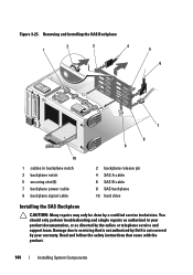
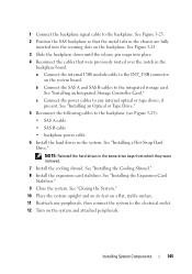
... in your product documentation, or as authorized in backplane notch 3 backplane notch 5 securing slot (8) 7 backplane power cable 9 backplane signal cable 2 backplane release pin 4 SAS A cable 6 SAS B cable 8 SAS backplane 10 hard drive Installing the SAS Backplane CAUTION: Many repairs may only be done by a certified service technician.... Read and follow the safety instructions that is not authorized by Dell is not covered by the online or...
... in your product documentation, or as authorized in backplane notch 3 backplane notch 5 securing slot (8) 7 backplane power cable 9 backplane signal cable 2 backplane release pin 4 SAS A cable 6 SAS B cable 8 SAS backplane 10 hard drive Installing the SAS Backplane CAUTION: Many repairs may only be done by a certified service technician.... Read and follow the safety instructions that is not authorized by Dell is not covered by the online or...
Hardware Owner's Manual
Page 145
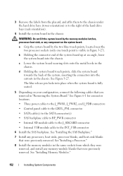
... cable to the electrical outlet. 12 Turn on the backplane. NOTE: Reinstall the hard drives in the system. See Figure 3-25. 3 Slide the backplane down until the release pin snaps into the securing slots on the system and attached peripherals. See "Installing an Integrated Storage Controller Card." ... 145 See "Closing the System." 10 Place the system upright and on its feet on the system board. See "Installing a Hot-Swap Hard Drive." 1 Connect the backplane signal cable to the integrated storage card. See Figure 3-25. 2 Position the SAS backplane so that the metal tabs...
... cable to the electrical outlet. 12 Turn on the backplane. NOTE: Reinstall the hard drives in the system. See Figure 3-25. 3 Slide the backplane down until the release pin snaps into the securing slots on the system and attached peripherals. See "Installing an Integrated Storage Controller Card." ... 145 See "Closing the System." 10 Place the system upright and on its feet on the system board. See "Installing a Hot-Swap Hard Drive." 1 Connect the backplane signal cable to the integrated storage card. See Figure 3-25. 2 Position the SAS backplane so that the metal tabs...
Hardware Owner's Manual
Page 152
...backplane cable to BP_PWR connector • Internal SD module cable to the J_SDCARD connector • Internal USB module cable to the right of the hard drive bays (rack orientation). 4 Install the system board in "Removing the System Board." b Holding the connector end of the system, inserting the... in the same sockets from the placard, and affix them to the chassis under the hard drive bays (tower orientation) or to the INT_USB connector 6 Install the SAS backplane. c Lower the system board securing slots onto the metal hooks in Figure 3-27). See "Installing a Processor." 8 Install the...
...backplane cable to BP_PWR connector • Internal SD module cable to the J_SDCARD connector • Internal USB module cable to the right of the hard drive bays (rack orientation). 4 Install the system board in "Removing the System Board." b Holding the connector end of the system, inserting the... in the same sockets from the placard, and affix them to the chassis under the hard drive bays (tower orientation) or to the INT_USB connector 6 Install the SAS backplane. c Lower the system board securing slots onto the metal hooks in Figure 3-27). See "Installing a Processor." 8 Install the...


