

Glossary
Page 1
... contains an address bus and a data bus for enabling the operating system to direct configuration and power management. Certificate authority. Dell™ Glossary NOTE: For additional information on storage terminology, visit the Storage Networking Industry Association's website at www.snia.org and... retrieval. Alternating current. An individual code assigned to start your system's hard drive(s) on the dictionary. The modules are mounted into a chassis that contains a processor, memory, and a hard drive. BMC - bootable media - Your system contains an expansion bus that keeps a...
... contains an address bus and a data bus for enabling the operating system to direct configuration and power management. Certificate authority. Dell™ Glossary NOTE: For additional information on storage terminology, visit the Storage Networking Industry Association's website at www.snia.org and... retrieval. Alternating current. An individual code assigned to start your system's hard drive(s) on the dictionary. The modules are mounted into a chassis that contains a processor, memory, and a hard drive. BMC - bootable media - Your system contains an expansion bus that keeps a...
Information Update - Intel Xeon 5600 Series Processors
Page 1
... update only supports a limited feature set of the Intel Xeon 5600 series processor. • The following new Dell PowerEdge systems marked with the Roman Numeral II on the chassis support the complete feature set of Intel Xeon 5500 and 5600 series processors is not supported. • Systems ... sparing. December 2010 T710 - M610 - R510 - NOTE: The modular systems, PowerEdge M610 and M710, support the 130 W Intel Xeon X5680 only in the 130 W processor category. You can download the BIOS and iDRAC firmware for the Intel Xeon 5600 series processor at support.dell.com. R410 - T610 -
... update only supports a limited feature set of the Intel Xeon 5600 series processor. • The following new Dell PowerEdge systems marked with the Roman Numeral II on the chassis support the complete feature set of Intel Xeon 5500 and 5600 series processors is not supported. • Systems ... sparing. December 2010 T710 - M610 - R510 - NOTE: The modular systems, PowerEdge M610 and M710, support the 130 W Intel Xeon X5680 only in the 130 W processor category. You can download the BIOS and iDRAC firmware for the Intel Xeon 5600 series processor at support.dell.com. R410 - T610 -
Tower-to-Rack Conversion Guide
Page 4
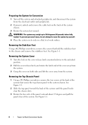
...feet inward. Removing the System Cover 1 Turn the lock on a flat, level work surface. See Figure 1-1. 4 Tower-to the chassis and remove the stabilizer feet. See Figure 1-1. Removing the Top Chassis Panel 1 Using a #2 Phillips screwdriver, remove the two screws at the back of the system. See Figure 1-1. 2 Slide the ...top panel toward the back of the system until the panel hooks clear the chassis slots. 3 Rotate the free side of the panel outward about 15 degrees and pull the panel clear of the system that hold the stabilizer...
...feet inward. Removing the System Cover 1 Turn the lock on a flat, level work surface. See Figure 1-1. 4 Tower-to the chassis and remove the stabilizer feet. See Figure 1-1. Removing the Top Chassis Panel 1 Using a #2 Phillips screwdriver, remove the two screws at the back of the system. See Figure 1-1. 2 Slide the ...top panel toward the back of the system until the panel hooks clear the chassis slots. 3 Rotate the free side of the panel outward about 15 degrees and pull the panel clear of the system that hold the stabilizer...
Tower-to-Rack Conversion Guide
Page 5
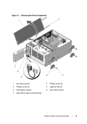
Figure 1-1. Removing the Tower Components 1 2 7 6 5 4 3 1 top chassis panel 3 Phillips screw (4) 5 LCD display module 7 optical drive (top or left drive bay) 2 Phillips screw (2) 4 stabilizer foot (4) 6 drive release latch Tower-to-Rack Conversion Guide 5
Figure 1-1. Removing the Tower Components 1 2 7 6 5 4 3 1 top chassis panel 3 Phillips screw (4) 5 LCD display module 7 optical drive (top or left drive bay) 2 Phillips screw (2) 4 stabilizer foot (4) 6 drive release latch Tower-to-Rack Conversion Guide 5
Tower-to-Rack Conversion Guide
Page 6
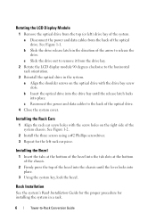
... Module 1 Remove the optical drive from the top (or left rack ear piece. a Disconnect the power and data cables from the back of the system chassis. See Figure 1-1. b Insert the optical drive into the drive bay until the lever locks into place. See Figure 1-2. 2 Install the three screws using a ...in the system. Rack Installation See the system's Rack Installation Guide for the proper procedure for the left ) drive bay of the bezel into the chassis until the release latch locks into place. 3 Using the system key, lock the bezel. Installing the Rack Ears 1 Align the rack ear screw...
... Module 1 Remove the optical drive from the top (or left rack ear piece. a Disconnect the power and data cables from the back of the system chassis. See Figure 1-1. b Insert the optical drive into the drive bay until the lever locks into place. See Figure 1-2. 2 Install the three screws using a ...in the system. Rack Installation See the system's Rack Installation Guide for the proper procedure for the left ) drive bay of the bezel into the chassis until the release latch locks into place. 3 Using the system key, lock the bezel. Installing the Rack Ears 1 Align the rack ear screw...

Installing the Optional Casters on your System
Page 1
...stabilizer foot at an angle, slide the two front metal tabs on the foot into the tab slot on the system and attached peripherals. A00 DELL CONFIDENTIAL - PRELIMINARY 12/17/08 - Installing the Optional Casters on your System The optional casters for property damage, personal injury, or death. See...to lift the system by removing the Phillips screws securing the feet (one screw per foot), which attach to the electrical outlet. 8 Turn on the chassis. b Rotate the foot towards the system, inserting the back metal tab into the tab slots in Figure 1. 4 Remove the four system feet by ...
...stabilizer foot at an angle, slide the two front metal tabs on the foot into the tab slot on the system and attached peripherals. A00 DELL CONFIDENTIAL - PRELIMINARY 12/17/08 - Installing the Optional Casters on your System The optional casters for property damage, personal injury, or death. See...to lift the system by removing the Phillips screws securing the feet (one screw per foot), which attach to the electrical outlet. 8 Turn on the chassis. b Rotate the foot towards the system, inserting the back metal tab into the tab slots in Figure 1. 4 Remove the four system feet by ...
Hardware Owner's Manual
Page 36
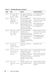
System Memory." Reseat DIMM. "## & ##" System Memory." Check chassis cover. system for 10 seconds and bit error (SBE) logging restart the system. Reseat DIMM. E2111 SBE log disabled on DIMM ##. System cover has been ...
System Memory." Reseat DIMM. "## & ##" System Memory." Check chassis cover. system for 10 seconds and bit error (SBE) logging restart the system. Reseat DIMM. E2111 SBE log disabled on DIMM ##. System cover has been ...
Hardware Owner's Manual
Page 79
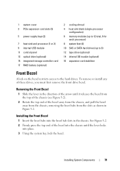
.... To remove or install any of the bezel into the chassis until it releases the bezel from the top of the chassis (see Figure 3-2). 2 Rotate the top end of the bezel away from the chassis, and pull the bezel away from the chassis, removing the bezel tabs from the slots as shown in... the chassis. Installing System Components 79 See Figure 3-2. 2 Firmly press the top...
.... To remove or install any of the bezel into the chassis until it releases the bezel from the top of the chassis (see Figure 3-2). 2 Rotate the top end of the bezel away from the chassis, and pull the bezel away from the chassis, removing the bezel tabs from the slots as shown in... the chassis. Installing System Components 79 See Figure 3-2. 2 Firmly press the top...
Hardware Owner's Manual
Page 82
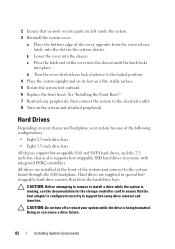
...has one of the following configurations: • Eight 2.5-inch drive bays • Eight 3.5-inch drive bays All chassis support hot-swappable SAS and SATA hard drives, and the 2.5inch-bay chassis also supports hot-swappable SSD hard drives in systems with integrated PERC controllers. Doing so can cause a drive ...failure. 82 Installing System Components c Press the latch end of the cover into the chassis until the latch locks into the slots in the hard-drive bays. All drives are installed at the front of the system and connect to...
...has one of the following configurations: • Eight 2.5-inch drive bays • Eight 3.5-inch drive bays All chassis support hot-swappable SAS and SATA hard drives, and the 2.5inch-bay chassis also supports hot-swappable SSD hard drives in systems with integrated PERC controllers. Doing so can cause a drive ...failure. 82 Installing System Components c Press the latch end of the cover into the chassis until the latch locks into the slots in the hard-drive bays. All drives are installed at the front of the system and connect to...
Hardware Owner's Manual
Page 83
Mixed 2.5-inch and 3.5-inch configurations of SAS and SATA drives are also supported in the 3.5-inch-bay chassis only. The remaining hard drives must be 3.5 inches in hard-drive slots 0 and 1 only. When you format a hard drive, allow enough time for use with ...
Mixed 2.5-inch and 3.5-inch configurations of SAS and SATA drives are also supported in the 3.5-inch-bay chassis only. The remaining hard drives must be 3.5 inches in hard-drive slots 0 and 1 only. When you format a hard drive, allow enough time for use with ...
Hardware Owner's Manual
Page 88
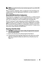
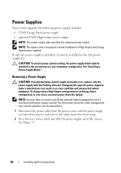
NOTE: The system does not support a mixed installation of the chassis. Removing a Power Supply CAUTION: If troubleshooting a power supply mismatch error, replace only the power supply with power supply removal. Swapping the opposite power supply to ...
NOTE: The system does not support a mixed installation of the chassis. Removing a Power Supply CAUTION: If troubleshooting a power supply mismatch error, replace only the power supply with power supply removal. Swapping the opposite power supply to ...
Hardware Owner's Manual
Page 89
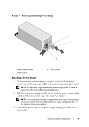
... you unlatched the cable management arm in watts) is located near the center of the power supply label. 2 Slide the new power supply into the chassis until the power supply is fully seated and the release latch snaps into a power outlet. For information about the cable management arm, see the system...
... you unlatched the cable management arm in watts) is located near the center of the power supply label. 2 Slide the new power supply into the chassis until the power supply is fully seated and the release latch snaps into a power outlet. For information about the cable management arm, see the system...
Hardware Owner's Manual
Page 90
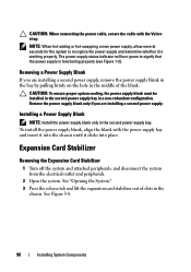
... the blank with the Velcro strap. CAUTION: When connecting the power cable, secure the cable with the power supply bay and insert it into the chassis until it is functioning properly (see Figure 1-5). Removing a Power Supply Blank If you are installing a second power supply, remove the power supply blank in the...
... the blank with the Velcro strap. CAUTION: When connecting the power cable, secure the cable with the power supply bay and insert it into the chassis until it is functioning properly (see Figure 1-5). Removing a Power Supply Blank If you are installing a second power supply, remove the power supply blank in the...
Hardware Owner's Manual
Page 91
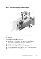
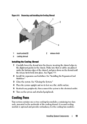
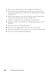
Figure 3-8. See "Closing the System." 3 Place the system upright and on its feet on a flat, stable surface. 4 Reattach any peripherals, then connect the system to the electrical outlet. 5 Turn on the system and attached peripherals. Installing System Components 91 See Figure 3-8. 2 Close the system. Removing and Installing the Expansion Card Stabilizer 2 1 3 1 release tab 3 chassis slots 2 expansion card stabilizer Installing the Expansion Card Stabilizer 1 Slide the edge of the expansion card stabilizer into the slots in the chassis until the release tab locks into place.
Figure 3-8. See "Closing the System." 3 Place the system upright and on its feet on a flat, stable surface. 4 Reattach any peripherals, then connect the system to the electrical outlet. 5 Turn on the system and attached peripherals. Installing System Components 91 See Figure 3-8. 2 Close the system. Removing and Installing the Expansion Card Stabilizer 2 1 3 1 release tab 3 chassis slots 2 expansion card stabilizer Installing the Expansion Card Stabilizer 1 Slide the edge of the expansion card stabilizer into the slots in the chassis until the release tab locks into place.
Hardware Owner's Manual
Page 92
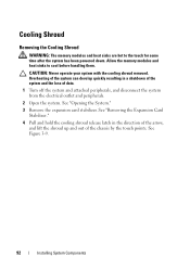
... removed. See "Removing the Expansion Card Stabilizer." 4 Pull and hold the cooling shroud release latch in a shutdown of the system and the loss of the chassis by the touch points. Cooling Shroud Removing the Cooling Shroud WARNING: The memory modules and heat sinks are hot to cool before handling them.
... removed. See "Removing the Expansion Card Stabilizer." 4 Pull and hold the cooling shroud release latch in a shutdown of the system and the loss of the chassis by the touch points. Cooling Shroud Removing the Cooling Shroud WARNING: The memory modules and heat sinks are hot to cool before handling them.
Hardware Owner's Manual
Page 93
... Reattach any peripherals, then connect the system to the electrical outlet. 6 Turn on the shroud until the release latch locks into the chassis, inserting the shroud edges in the alignment guides in the underside of the shroud, and press down on the system and attached peripherals.... Cooling Fans Your system contains one or two cooling-fan modules, containing two fans each, mounted in the chassis. A second cooling module is optional and provides redundancy for the cooling-fan modules. See "Installing the Expansion Card Stabilizer." 3 Close the ...
... Reattach any peripherals, then connect the system to the electrical outlet. 6 Turn on the shroud until the release latch locks into the chassis, inserting the shroud edges in the alignment guides in the underside of the shroud, and press down on the system and attached peripherals.... Cooling Fans Your system contains one or two cooling-fan modules, containing two fans each, mounted in the chassis. A second cooling module is optional and provides redundancy for the cooling-fan modules. See "Installing the Expansion Card Stabilizer." 3 Close the ...
Hardware Owner's Manual
Page 96
... SD Module Installing the Internal SD Module 1 Turn off the system, including any peripherals, then connect the system to the electrical outlet. 8 Turn on the chassis, then lower the opposite edge of the card into place.
... SD Module Installing the Internal SD Module 1 Turn off the system, including any peripherals, then connect the system to the electrical outlet. 8 Turn on the chassis, then lower the opposite edge of the card into place.
Hardware Owner's Manual
Page 98
... Expansion Card Stabilizer." 4 Remove the cooling shroud. Removing the Internal SD Module 1 Turn off the system, including any peripherals, then connect the system to the chassis, then lift the module out of the chassis. 8 Install the expansion card stabilizer. See "Installing the Expansion Card Stabilizer." 9 Close the system.
... Expansion Card Stabilizer." 4 Remove the cooling shroud. Removing the Internal SD Module 1 Turn off the system, including any peripherals, then connect the system to the chassis, then lift the module out of the chassis. 8 Install the expansion card stabilizer. See "Installing the Expansion Card Stabilizer." 9 Close the system.
Hardware Owner's Manual
Page 100
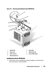
... upright and on its feet on a flat, stable surface. 11 Reattach any peripherals, then connect the system to remove it from the slots in the chassis. See "Installing the Cooling Shroud." 8 Install the expansion card stabilizer. See Figure 3-12. 6 Pull up on the module release tab, and slide the internal USB.... 7 Install the cooling shroud. 4 Remove the cooling shroud. See "Removing the Cooling Shroud." 5 Disconnect the internal USB module cable from the cable guides in the chassis.
... upright and on its feet on a flat, stable surface. 11 Reattach any peripherals, then connect the system to remove it from the slots in the chassis. See "Installing the Cooling Shroud." 8 Install the expansion card stabilizer. See Figure 3-12. 6 Pull up on the module release tab, and slide the internal USB.... 7 Install the cooling shroud. 4 Remove the cooling shroud. See "Removing the Cooling Shroud." 5 Disconnect the internal USB module cable from the cable guides in the chassis.
Hardware Owner's Manual
Page 101
Installing System Components 101 Removing and Installing the Internal USB Module 5 4 6 3 7 2 1 1 chassis slots 3 module tabs 5 cable connector 7 module release tab 2 cable guide 4 USB memory key 6 internal USB module Installing the Internal USB Module 1 Turn off the system, including any attached peripherals, and disconnect the system from its electrical outlet. Figure 3-12.
Installing System Components 101 Removing and Installing the Internal USB Module 5 4 6 3 7 2 1 1 chassis slots 3 module tabs 5 cable connector 7 module release tab 2 cable guide 4 USB memory key 6 internal USB module Installing the Internal USB Module 1 Turn off the system, including any attached peripherals, and disconnect the system from its electrical outlet. Figure 3-12.


