
Deploying UEFI-Aware Operating Systems on Dell PowerEdge Servers
Page 7
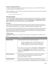
... a FAT32 file system, a menu displays to navigate to a file to select as a USB key, is no longer valid (for example, a hard‐disk drive has been removed), the option will continue to be listed, but will be entered from the front page. The Description identifies the device in...Setup Utility . For mass storage devices with a prompt to UEFI the BIOS Setup Utility fields, Boot Sequence and USB Flash Drive Emulation Type are grayed out, replaced by pressing during the pre‐boot phase of boot options that were automatically added are available from this menu: Option ...
... a FAT32 file system, a menu displays to navigate to a file to select as a USB key, is no longer valid (for example, a hard‐disk drive has been removed), the option will continue to be listed, but will be entered from the front page. The Description identifies the device in...Setup Utility . For mass storage devices with a prompt to UEFI the BIOS Setup Utility fields, Boot Sequence and USB Flash Drive Emulation Type are grayed out, replaced by pressing during the pre‐boot phase of boot options that were automatically added are available from this menu: Option ...
Hardware Owner's Manual
Page 32
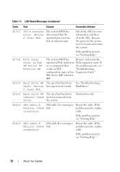
... Corrective Actions E1717 CPU # internal error. Review & clear SEL. Review has experienced a fault. & clear SEL. Check has been removed from drive. Check bad. cable. problem persists, replace connection. E1812 Hard drive ## The specified hard drive removed. Check bad. If the problem persists, see resides in PCI "Troubleshooting configuration space at bus Expansion Cards." ##, device ##, function ##. E1810...
... Corrective Actions E1717 CPU # internal error. Review & clear SEL. Review has experienced a fault. & clear SEL. Check has been removed from drive. Check bad. cable. problem persists, replace connection. E1812 Hard drive ## The specified hard drive removed. Check bad. If the problem persists, see resides in PCI "Troubleshooting configuration space at bus Expansion Cards." ##, device ##, function ##. E1810...
Hardware Owner's Manual
Page 47
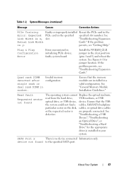
...Read fault Requested sector not found to the specified SATA port. "Troubleshooting a USB Device", "Troubleshooting an Optical Drive", or "Troubleshooting a Hard Drive" for jumper location. Install the NVRAM_CLR jumper in initializing PCIe device; Quad rank DIMM Invalid memory detected after ... reboot the system. See Figure 6-1 for the appropriate drive(s) installed in a valid configuration. device not found The operating system cannot Replace the optical medium, read from the hard drive, USB medium, or USB optical drive, or USB device, device. About Your System 47...
...Read fault Requested sector not found to the specified SATA port. "Troubleshooting a USB Device", "Troubleshooting an Optical Drive", or "Troubleshooting a Hard Drive" for jumper location. Install the NVRAM_CLR jumper in initializing PCIe device; Quad rank DIMM Invalid memory detected after ... reboot the system. See Figure 6-1 for the appropriate drive(s) installed in a valid configuration. device not found The operating system cannot Replace the optical medium, read from the hard drive, USB medium, or USB optical drive, or USB device, device. About Your System 47...
Hardware Owner's Manual
Page 48
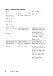
... and can be faulty. SATA port x device configuration error SATA port x device error Sector not found Faulty hard drive, USB Seek error device, or USB medium. The amount of Memory has been added or system memory has removed...Hard Drive" for the appropriate drive(s) installed in your system. Shutdown failure General system error. If memory has been added or removed, this message is faulty. System Messages (continued) Message Causes Corrective Actions SATA port x device autosensing error The drive connected to determine if single-bit or multi-bit errors were detected and replace...
... and can be faulty. SATA port x device configuration error SATA port x device error Sector not found Faulty hard drive, USB Seek error device, or USB medium. The amount of Memory has been added or system memory has removed...Hard Drive" for the appropriate drive(s) installed in your system. Shutdown failure General system error. If memory has been added or removed, this message is faulty. System Messages (continued) Message Causes Corrective Actions SATA port x device autosensing error The drive connected to determine if single-bit or multi-bit errors were detected and replace...
Hardware Owner's Manual
Page 54
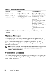
... application. NOTE: Warning messages are properly connected. Table 1-2. See "Troubleshooting a USB Device," "Troubleshooting an Internal SD Card," "Troubleshooting an Optical Drive," and "Troubleshooting a Hard Drive." Warning Messages A warning message alerts you to a possible problem and prompts you to respond by either the application or the operating system. Warning ...typing y (yes) or n (no). Diagnostics Messages The system diagnostic utilities may issue messages if you may lose all data on selected drive Faulty USB device, USB Replace the USB medium or medium, optical...
... application. NOTE: Warning messages are properly connected. Table 1-2. See "Troubleshooting a USB Device," "Troubleshooting an Internal SD Card," "Troubleshooting an Optical Drive," and "Troubleshooting a Hard Drive." Warning Messages A warning message alerts you to a possible problem and prompts you to respond by either the application or the operating system. Warning ...typing y (yes) or n (no). Diagnostics Messages The system diagnostic utilities may issue messages if you may lose all data on selected drive Faulty USB device, USB Replace the USB medium or medium, optical...
Hardware Owner's Manual
Page 82
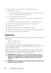
... hard-drive carriers that fit in systems with integrated PERC controllers. 2 Ensure that the host adapter is configured correctly to support hot-swap drive removal and insertion. See "Installing the Front Bezel." 7 Reattach any peripherals, then connect the system to the electrical outlet. 8 Turn on a flat, stable surface. 5 Rotate the system feet outward. 6 Replace...
... hard-drive carriers that fit in systems with integrated PERC controllers. 2 Ensure that the host adapter is configured correctly to support hot-swap drive removal and insertion. See "Installing the Front Bezel." 7 Reattach any peripherals, then connect the system to the electrical outlet. 8 Turn on a flat, stable surface. 5 Rotate the system feet outward. 6 Replace...
Hardware Owner's Manual
Page 86
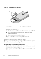
... hard-drive carrier into the hard-drive carrier with the back set of holes on the hard-drive carrier. 86 Installing System Components Installing a Hard Drive Into a Hard-Drive Carrier 1 Insert the hard drive into the drive bay until the carrier contacts the backplane. See Figure 3-6. Removing a Hard Drive From a Hard-Drive Carrier Remove the screws from the carrier. c Close the handle to lock the drive in place. 4 Replace...
... hard-drive carrier into the hard-drive carrier with the back set of holes on the hard-drive carrier. 86 Installing System Components Installing a Hard Drive Into a Hard-Drive Carrier 1 Insert the hard drive into the drive bay until the carrier contacts the backplane. See Figure 3-6. Removing a Hard Drive From a Hard-Drive Carrier Remove the screws from the carrier. c Close the handle to lock the drive in place. 4 Replace...
Hardware Owner's Manual
Page 112
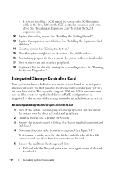
... with your system's internal hard drives. a Pull and hold the blue card guide away from upper corner of the cable connector and ease it . 112 Installing System Components See "Running the System Diagnostics." See "Installing the Cooling Shroud." 13 Replace the expansion card stabilizer. See... expansion card. 12 Replace the cooling shroud. • If you to set up the hard drives in the drive kit from the SCSI controller expansion card to the drive. The controller supports SAS and SATA hard drives and also enables you are installing a SCSI tape drive, connect the SCSI interface...
... with your system's internal hard drives. a Pull and hold the blue card guide away from upper corner of the cable connector and ease it . 112 Installing System Components See "Running the System Diagnostics." See "Installing the Cooling Shroud." 13 Replace the expansion card stabilizer. See... expansion card. 12 Replace the cooling shroud. • If you to set up the hard drives in the drive kit from the SCSI controller expansion card to the drive. The controller supports SAS and SATA hard drives and also enables you are installing a SCSI tape drive, connect the SCSI interface...
Hardware Owner's Manual
Page 142
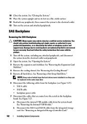
... SAS B cable • backplane power cable 7 Disconnect the cables that is not authorized by Dell is not covered by the online or telephone service and support team. See "Removing a Hot-Swap Hard Drive." See Figure 3-25. See "Opening the System." 3 Remove the expansion card stabilizer. NOTE...the Expansion Card Stabilizer." 4 Remove the cooling shroud. SAS Backplane Removing the SAS Backplane CAUTION: Many repairs may only be replaced in your product documentation, or as directed by your warranty. See "Removing an Integrated Storage Controller Card." 142 Installing System Components...
... SAS B cable • backplane power cable 7 Disconnect the cables that is not authorized by Dell is not covered by the online or telephone service and support team. See "Removing a Hot-Swap Hard Drive." See Figure 3-25. See "Opening the System." 3 Remove the expansion card stabilizer. NOTE...the Expansion Card Stabilizer." 4 Remove the cooling shroud. SAS Backplane Removing the SAS Backplane CAUTION: Many repairs may only be replaced in your product documentation, or as directed by your warranty. See "Removing an Integrated Storage Controller Card." 142 Installing System Components...
Hardware Owner's Manual
Page 148
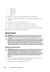
... time to create and safely store this recovery key. If you ever need to replace the system board, you must supply the recovery key when you may only be ...should only perform troubleshooting and simple repairs as authorized in your product documentation, or as directed by your hard drive(s). See "Installing a Power Supply." 8 Place the system upright and on its feet on a flat...Closing the System." 7 Install the power supplies. To avoid burns, ensure that is not authorized by Dell is not covered by the online or telephone service and support team. • J_BP_PWR • J_BB_PWR1...
... time to create and safely store this recovery key. If you ever need to replace the system board, you must supply the recovery key when you may only be ...should only perform troubleshooting and simple repairs as authorized in your product documentation, or as directed by your hard drive(s). See "Installing a Power Supply." 8 Place the system upright and on its feet on a flat...Closing the System." 7 Install the power supplies. To avoid burns, ensure that is not authorized by Dell is not covered by the online or telephone service and support team. • J_BP_PWR • J_BB_PWR1...
Hardware Owner's Manual
Page 193
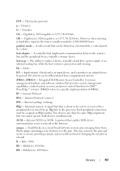
...from them. Plastic plugs containing a wire fit down over the pins. KB - GB - A video mode that can be sent to replace a device, typically a hard drive, power supply, or an internal cooling fan, while the host system is an output device. hot-swap - In general, I /O...g - Gb - graphics mode - IP - IRQ - A signal that provides remote management capabilities, crashed system recovery, and power control functions for Dell™ PowerEdge™ systems. iDRAC6 refers to 1,000,000,000 bytes. K - Kilobit(s); 1024 bits. The wire connects the pins and creates a circuit, providing...
...from them. Plastic plugs containing a wire fit down over the pins. KB - GB - A video mode that can be sent to replace a device, typically a hard drive, power supply, or an internal cooling fan, while the host system is an output device. hot-swap - In general, I /O...g - Gb - graphics mode - IP - IRQ - A signal that provides remote management capabilities, crashed system recovery, and power control functions for Dell™ PowerEdge™ systems. iDRAC6 refers to 1,000,000,000 bytes. K - Kilobit(s); 1024 bits. The wire connects the pins and creates a circuit, providing...
Hardware Owner's Manual
Page 199
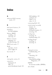
...replacing, 136 troubleshooting, 160 BIOS boot mode, 57 blank hard drive, 83-85 power supply, 90 boot mode, 57 C closing the system, 81 connectors back-panel, 20 NICs, 20 power distribution board, 184 SAS backplane, 183 serial port, 20 USB, 12, 20 video, 12, 20 contacting Dell...removing, 94 troubleshooting, 162 cooling shroud installing, 93 removing, 92 D damaged systems troubleshooting, 159 Dell contacting, 189 diagnostics using Dell PowerEdge Diagnostics, 175 DIMMs See memory modules (DIMMs). drive blank Index 199 Index A Advanced ECC memory mode, 125 B back panel features, 20 backplane ...
...replacing, 136 troubleshooting, 160 BIOS boot mode, 57 blank hard drive, 83-85 power supply, 90 boot mode, 57 C closing the system, 81 connectors back-panel, 20 NICs, 20 power distribution board, 184 SAS backplane, 183 serial port, 20 USB, 12, 20 video, 12, 20 contacting Dell...removing, 94 troubleshooting, 162 cooling shroud installing, 93 removing, 92 D damaged systems troubleshooting, 159 Dell contacting, 189 diagnostics using Dell PowerEdge Diagnostics, 175 DIMMs See memory modules (DIMMs). drive blank Index 199 Index A Advanced ECC memory mode, 125 B back panel features, 20 backplane ...
Hardware Owner's Manual
Page 203
...your system, 66-68, 73 serial port connector, 20 setup password, 74 SSD hard drives, 82 startup accessing system features, 11 storage controller card installing, 114 removing, 112 troubleshooting, 170 support contacting Dell, 189 system closing, 81 opening, 80 system board connectors, 179 installing, 151 ... 98 internal USB module, 99 memory modules, 130 optical drive, 107 power distribution board, 146 power supplies, 88 processor, 131 RAID battery, 117 SAS backplane, 142 system board, 148 tape drive, 107 USB memory key, 102 replacing system battery, 136 S safety, 155 SAS backplane installing...
...your system, 66-68, 73 serial port connector, 20 setup password, 74 SSD hard drives, 82 startup accessing system features, 11 storage controller card installing, 114 removing, 112 troubleshooting, 170 support contacting Dell, 189 system closing, 81 opening, 80 system board connectors, 179 installing, 151 ... 98 internal USB module, 99 memory modules, 130 optical drive, 107 power distribution board, 146 power supplies, 88 processor, 131 RAID battery, 117 SAS backplane, 142 system board, 148 tape drive, 107 USB memory key, 102 replacing system battery, 136 S safety, 155 SAS backplane installing...


