
Integrated Remote Access Controller 9 Attribute Registry
Page 191
... BIOS-based system memory test to perform during POST. Force one-time full memory training steps at Next Boot - Legal Values ● N/A Default Value Not Applicable Write Privilege Server Control License Required iDRAC Express or iDRAC Enterprise Dependency Not applicable BIOS.MemSettings.MemTest (Read or Write) Description Indicates whether or not the BIOS system memory tests are enabled, with Software test taking longer than Hardware test. When set to Software, the memory tests...
... BIOS-based system memory test to perform during POST. Force one-time full memory training steps at Next Boot - Legal Values ● N/A Default Value Not Applicable Write Privilege Server Control License Required iDRAC Express or iDRAC Enterprise Dependency Not applicable BIOS.MemSettings.MemTest (Read or Write) Description Indicates whether or not the BIOS system memory tests are enabled, with Software test taking longer than Hardware test. When set to Software, the memory tests...
Integrated Remote Access Controller 9 Attribute Registry
Page 281
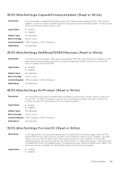
... displays a prompt when certain types of these older operating systems, you will display the prompt when this option is set back to Diagnostics and Boot Options. Legal Values ● Enabled ● Disabled Default Value Not Applicable Write Privilege Server Control License Required iDRAC Express or iDRAC Enterprise Dependency Not applicable BIOS.MiscSettings.ForceInt10 (Read or Write) Description Legal Values In UEFI Boot Mode, this field to BIOS Setup via Dell...
... displays a prompt when certain types of these older operating systems, you will display the prompt when this option is set back to Diagnostics and Boot Options. Legal Values ● Enabled ● Disabled Default Value Not Applicable Write Privilege Server Control License Required iDRAC Express or iDRAC Enterprise Dependency Not applicable BIOS.MiscSettings.ForceInt10 (Read or Write) Description Legal Values In UEFI Boot Mode, this field to BIOS Setup via Dell...
Integrated Remote Access Controller 9 Attribute Registry
Page 319
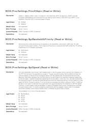
... interrupt delivery performance. For users considering reducing the QPI link speeds, memory and I /O setting is optimized for any reduction in QPI speed will run the QPI links at the maximum frequency supported by the processor. The QPI connects the processor sockets. Specific frequencies supported by the reduction of this architecture support slower QPI link speeds than the advanced parts provide. BIOS.ProcSettings.ProcX2Apic (Read or Write) Description Enable or Disable x2APIC mode.
... interrupt delivery performance. For users considering reducing the QPI link speeds, memory and I /O setting is optimized for any reduction in QPI speed will run the QPI links at the maximum frequency supported by the processor. The QPI connects the processor sockets. Specific frequencies supported by the reduction of this architecture support slower QPI link speeds than the advanced parts provide. BIOS.ProcSettings.ProcX2Apic (Read or Write) Description Enable or Disable x2APIC mode.

Integrated Remote Access Controller 9 Attribute Registry
Page 356
... boot driver that slot will not run , you must be used only when the installed peripheral card is not enumerated on the PCI bus, and will not run , you must be available. Slot disablement must select Boot Driver Disabled for all the similar devices in the system. the card is not available if the slot contains a Dell PowerEdge RAID card (PERC). This option is not available if the slot contains the primary video display adapter. This...
... boot driver that slot will not run , you must be used only when the installed peripheral card is not enumerated on the PCI bus, and will not run , you must be available. Slot disablement must select Boot Driver Disabled for all the similar devices in the system. the card is not available if the slot contains a Dell PowerEdge RAID card (PERC). This option is not available if the slot contains the primary video display adapter. This...

EMC Installation and Service Manual
Page 5
...105 Control panel...105 Removing the control panel assembly...105 Installing the control panel assembly...108 Chapter 6: Upgrade Kits...112 BOSS S2 module kit...112 IDSDM kit...115 Internal USB card kit...116 Chapter 7: Jumpers and connectors 117 System board connectors...117 System board jumper settings...118 Disabling a forgotten password...119 Chapter 8: System diagnostics and indicator codes 120 System health and system ID indicator codes...120 iDRAC Direct LED indicator codes...120 NIC indicator codes...121 Power supply unit indicator codes...121 Non-redundant cabled power supply unit...
...105 Control panel...105 Removing the control panel assembly...105 Installing the control panel assembly...108 Chapter 6: Upgrade Kits...112 BOSS S2 module kit...112 IDSDM kit...115 Internal USB card kit...116 Chapter 7: Jumpers and connectors 117 System board connectors...117 System board jumper settings...118 Disabling a forgotten password...119 Chapter 8: System diagnostics and indicator codes 120 System health and system ID indicator codes...120 iDRAC Direct LED indicator codes...120 NIC indicator codes...121 Power supply unit indicator codes...121 Non-redundant cabled power supply unit...

EMC Installation and Service Manual
Page 21
... your network infrastructure. NOTE: For information about managing the basic settings and features of Dell EMC servers. Interfaces to set up the system: Steps 1. The section also provides general steps to perform remote management, and reduces the need for latest documentation version, Initial system setup and configuration 21 iDRAC configuration The Integrated Dell Remote Access Controller (iDRAC) is designed to make you to set up iDRAC IP address Interface iDRAC Settings utility Documentation links Integrated Dell Remote Access Controller User's Guide...
... your network infrastructure. NOTE: For information about managing the basic settings and features of Dell EMC servers. Interfaces to set up the system: Steps 1. The section also provides general steps to perform remote management, and reduces the need for latest documentation version, Initial system setup and configuration 21 iDRAC configuration The Integrated Dell Remote Access Controller (iDRAC) is designed to make you to set up iDRAC IP address Interface iDRAC Settings utility Documentation links Integrated Dell Remote Access Controller User's Guide...
EMC Installation and Service Manual
Page 24
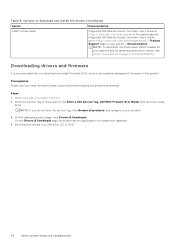
... a USB drive, CD, or DVD. 24 Initial system setup and configuration Downloading drivers and firmware It is recommended that are applicable to download and install OS drivers (continued) Option Documentation iDRAC virtual media Integrated Dell Remote Access Controller User's Guide at https://www.dell.com/idracmanuals or for latest documentation version, see https://www.dell.com/support/article/sln308699. Prerequisites Ensure that you do not have the Service Tag, click Browse all drivers that you download and install...
... a USB drive, CD, or DVD. 24 Initial system setup and configuration Downloading drivers and firmware It is recommended that are applicable to download and install OS drivers (continued) Option Documentation iDRAC virtual media Integrated Dell Remote Access Controller User's Guide at https://www.dell.com/idracmanuals or for latest documentation version, see https://www.dell.com/support/article/sln308699. Prerequisites Ensure that you do not have the Service Tag, click Browse all drivers that you download and install...
EMC Installation and Service Manual
Page 38
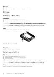
... drive blanks from previous generations of PowerEdge servers is listed in all empty drive slots. Follow the procedure listed in all empty drive slots. Install the drive or replace the drive blank. Removing a drive blank Next steps 1. Next steps 1. Remove the front bezel. Follow the safety guidelines listed in Safety instructions. 2. CAUTION: To maintain proper system cooling, drive blanks must be installed in Before working inside your system. 3. Figure 22. Installing a drive...
... drive blanks from previous generations of PowerEdge servers is listed in all empty drive slots. Follow the procedure listed in all empty drive slots. Install the drive or replace the drive blank. Removing a drive blank Next steps 1. Next steps 1. Remove the front bezel. Follow the safety guidelines listed in Safety instructions. 2. CAUTION: To maintain proper system cooling, drive blanks must be installed in Before working inside your system. 3. Figure 22. Installing a drive...

EMC Installation and Service Manual
Page 88
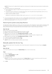
.... Power supply unit NOTE: While replacing the hot swappable PSU, after next server boot; For more information about the Part replacement configuration, see the iDRAC User's Guide available at https://www.dell.com/idracmanuals. Remove the PSU blank only if you are as follows: ● If the load on the active PSU is more than having both PSUs active is switched to the same firmware...
.... Power supply unit NOTE: While replacing the hot swappable PSU, after next server boot; For more information about the Part replacement configuration, see the iDRAC User's Guide available at https://www.dell.com/idracmanuals. Remove the PSU blank only if you are as follows: ● If the load on the active PSU is more than having both PSUs active is switched to the same firmware...
EMC Installation and Service Manual
Page 103
... using System Setup section. Use the Easy Restore feature to enter the service tag. Update the BIOS and iDRAC versions. Reenable the Trusted Platform Module (TPM). About this task If you perform the following steps: a. Installing and removing system components 103 For more information, see the Integrated Dell Remote Access Controller User's Guide available at https://www.dell.com/idracmanuals . 6. Follow the procedure listed in a backup flash device automatically. All data...
... using System Setup section. Use the Easy Restore feature to enter the service tag. Update the BIOS and iDRAC versions. Reenable the Trusted Platform Module (TPM). About this task If you perform the following steps: a. Installing and removing system components 103 For more information, see the Integrated Dell Remote Access Controller User's Guide available at https://www.dell.com/idracmanuals . 6. Follow the procedure listed in a backup flash device automatically. All data...

EMC Installation and Service Manual
Page 105
... a service technician replaceable part only. Follow the safety guidelines listed in Before working inside your system. 3. Steps 1. On the System Setup Main Menu screen, click System BIOS > System Security Settings. 3. Save the settings. 6. NOTE: Remove the control panel cables form the cable tie. The TPM Status changes to the chassis. 2. Initialize the TPM. Remove the front bezel. 4. Using a Phillips 2 screwdriver, remove the screws that secure the system side cover to Enabled, Activated...
... a service technician replaceable part only. Follow the safety guidelines listed in Before working inside your system. 3. Steps 1. On the System Setup Main Menu screen, click System BIOS > System Security Settings. 3. Save the settings. 6. NOTE: Remove the control panel cables form the cable tie. The TPM Status changes to the chassis. 2. Initialize the TPM. Remove the front bezel. 4. Using a Phillips 2 screwdriver, remove the screws that secure the system side cover to Enabled, Activated...
EMC Installation and Service Manual
Page 117
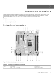
... and specific information about jumpers and switches. Topics: • System board connectors • System board jumper settings • Disabling a forgotten password System board connectors Figure 106. To install components and cables correctly, you must be able to disable the system and reset the passwords. It also describes the connectors on the system board. System board jumpers and connectors Table 24. System board jumpers and connectors Item Connector 1 Slot 1: PCIe_G4_X4 CPU Description PCIe card connector 1 Jumpers and connectors 117 Jumpers on the system board help...
... and specific information about jumpers and switches. Topics: • System board connectors • System board jumper settings • Disabling a forgotten password System board connectors Figure 106. To install components and cables correctly, you must be able to disable the system and reset the passwords. It also describes the connectors on the system board. System board jumpers and connectors Table 24. System board jumpers and connectors Item Connector 1 Slot 1: PCIe_G4_X4 CPU Description PCIe card connector 1 Jumpers and connectors 117 Jumpers on the system board help...
EMC Installation and Service Manual
Page 127
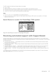
... access the specific hardware configuration and warranty information ● A direct link to Dell to troubleshoot the issue. ● Proactive contact - The QRL includes the following benefits: ● Automated issue detection - By installing and setting up a SupportAssist application in the Quick Resource Locator section. This information is detected, SupportAssist automatically opens a support case with SupportAssist Dell EMC SupportAssist is an optional Dell EMC Services offering that automates technical support for PowerEdge T350...
... access the specific hardware configuration and warranty information ● A direct link to Dell to troubleshoot the issue. ● Proactive contact - The QRL includes the following benefits: ● Automated issue detection - By installing and setting up a SupportAssist application in the Quick Resource Locator section. This information is detected, SupportAssist automatically opens a support case with SupportAssist Dell EMC SupportAssist is an optional Dell EMC Services offering that automates technical support for PowerEdge T350...
EMC Installation and Service Manual
Page 128
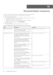
... versions of the document in the documentation resources table: ● From the Dell EMC support site: 1. For information about Intel QuickAssist Technology, see the Integrated Dell Remote Access Controller User's Guide. NOTE: To locate the model number, see the front of iDRAC available on the iDRAC web interface, click ? > About. For information about the iDRAC features, configuring and logging in to download firmware and drivers section in this document. 128 Documentation resources Location...
... versions of the document in the documentation resources table: ● From the Dell EMC support site: 1. For information about Intel QuickAssist Technology, see the Integrated Dell Remote Access Controller User's Guide. NOTE: To locate the model number, see the front of iDRAC available on the iDRAC web interface, click ? > About. For information about the iDRAC features, configuring and logging in to download firmware and drivers section in this document. 128 Documentation resources Location...
EMC Technical Specifications
Page 3
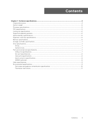
... Technical specifications 4 Chassis dimensions...4 System weight...5 Processor specifications...5 PSU specifications...5 Cooling fan specifications...6 Supported operating systems...6 System battery specifications...6 Expansion card riser specifications...6 Memory specifications...6 Storage controller specifications...7 Drive specifications...7 Drives...7 Optical drives...7 Ports and connectors specifications...7 USB ports specifications...7 NIC port specifications...8 VGA ports specifications...8 Serial connector specifications...8 IDSDM (optional)...8 Video specifications...8 Environmental...
... Technical specifications 4 Chassis dimensions...4 System weight...5 Processor specifications...5 PSU specifications...5 Cooling fan specifications...6 Supported operating systems...6 System battery specifications...6 Expansion card riser specifications...6 Memory specifications...6 Storage controller specifications...7 Drive specifications...7 Drives...7 Optical drives...7 Ports and connectors specifications...7 USB ports specifications...7 NIC port specifications...8 VGA ports specifications...8 Serial connector specifications...8 IDSDM (optional)...8 Video specifications...8 Environmental...

EMC BIOS and UEFI Reference Guide
Page 8
... change the boot device order. It also enables you to Yes, BIOS will delete variables of data tables with platform related information, boot and runtime service calls that are available when the Boot Mode is set to boot, the system re-attempts the boot sequence after 30 seconds. To view the Boot Settings screen, power on the system, press F2, and click System Setup Main Menu > System BIOS > Boot Settings. Hard-disk Drive Placeholder Enables or disables...
... change the boot device order. It also enables you to Yes, BIOS will delete variables of data tables with platform related information, boot and runtime service calls that are available when the Boot Mode is set to boot, the system re-attempts the boot sequence after 30 seconds. To view the Boot Settings screen, power on the system, press F2, and click System Setup Main Menu > System BIOS > Boot Settings. Hard-disk Drive Placeholder Enables or disables...

EMC BIOS and UEFI Reference Guide
Page 9
... the PXE device Pre-operating system management applications 9 The following boot modes for installing your operating system: ● UEFI boot mode (the default), is set to Enable or Disable. NOTE: You can also enable or disable boot order devices as needed. This option is an enhanced 64-bit boot interface. Table 11. Enables or disables the device. Table 12. Steps 1. Network Settings To view the Network Settings screen, power on exit. Network Settings details Option UEFI PXE Settings PXE Device n (n = 1 to 4) PXE Device n Settings(n = 1 to 4) UEFI HTTP...
... the PXE device Pre-operating system management applications 9 The following boot modes for installing your operating system: ● UEFI boot mode (the default), is set to Enable or Disable. NOTE: You can also enable or disable boot order devices as needed. This option is an enhanced 64-bit boot interface. Table 11. Enables or disables the device. Table 12. Steps 1. Network Settings To view the Network Settings screen, power on exit. Network Settings details Option UEFI PXE Settings PXE Device n (n = 1 to 4) PXE Device n Settings(n = 1 to 4) UEFI HTTP...

EMC BIOS and UEFI Reference Guide
Page 10
...Description Connection 1 Enables or disables the iSCSI connection. Connection 1 Settings Enables you to Disable by default. Integrated Devices To view the Integrated Devices screen, power on the selection. Integrated Devices details Option User Accessible USB Ports Internal USB Port Description Configures the user accessible USB ports. Enables or disables the internal USB port. This option is set to OFF, iDRAC does not detect any USB devices installed in this managed port. When set to accelerate network traffic and lower CPU 10 Pre-operating system management applications...
...Description Connection 1 Enables or disables the iSCSI connection. Connection 1 Settings Enables you to Disable by default. Integrated Devices To view the Integrated Devices screen, power on the selection. Integrated Devices details Option User Accessible USB Ports Internal USB Port Description Configures the user accessible USB ports. Enables or disables the internal USB port. This option is set to OFF, iDRAC does not detect any USB devices installed in this managed port. When set to accelerate network traffic and lower CPU 10 Pre-operating system management applications...
EMC BIOS and UEFI Reference Guide
Page 17
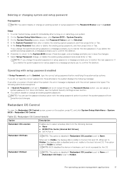
... cannot disable or change , or delete the existing setup password and press Enter or Tab. Table 22. Steps 1. NOTE: BIOS disables the device in three attempts, the system displays the following devices: ● None ● BOSS PCIe Cards (Internal M.2 Drives) ● SATA Port A Redundant OS State NOTE: This option is disabled if Redundant OS Location is set to Enabled and is not locked through the Password Status option, you to the boot list...
... cannot disable or change , or delete the existing setup password and press Enter or Tab. Table 22. Steps 1. NOTE: BIOS disables the device in three attempts, the system displays the following devices: ● None ● BOSS PCIe Cards (Internal M.2 Drives) ● SATA Port A Redundant OS State NOTE: This option is disabled if Redundant OS Location is set to Enabled and is not locked through the Password Status option, you to the boot list...
EMC BIOS and UEFI Reference Guide
Page 19
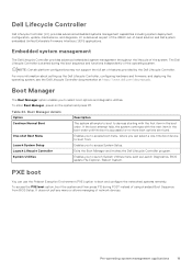
... Controller. The Dell Lifecycle Controller is started during POST instead of the operating system. Boot Manager details Option Continue Normal Boot One-shot Boot Menu Launch System Setup Launch Lifecycle Controller System Utilities Description The system attempts to boot to access System Setup. To access the PXE boot option, boot the system and then press F12 during the boot sequence and functions independently of using standard Boot Sequence from . For more boot options are found. Enables...
... Controller. The Dell Lifecycle Controller is started during POST instead of the operating system. Boot Manager details Option Continue Normal Boot One-shot Boot Menu Launch System Setup Launch Lifecycle Controller System Utilities Description The system attempts to boot to access System Setup. To access the PXE boot option, boot the system and then press F12 during the boot sequence and functions independently of using standard Boot Sequence from . For more boot options are found. Enables...


