Getting Started Guide
Page 10
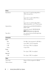
Drives Hard drives Optical drive Tape drive Connectors Back NIC Serial USB Video Front USB Internal USB Video Video type Video memory Up to four 3.5-inch hot-plug SAS or SATA internal drives or Up to four 3.5-inch cabled SAS or SATA ... hot-plug SAS or SSD internal drives in iDRAC 8 MB 8 Getting Started With Your System Optional internal SATA DVD-ROM or DVD+/-RW Optional external USB DVD-ROM NOTE: DVD devices are data only. One optional internal half height tape backup device Two RJ-45 (for integrated 1-GB NICs) 9-pin, DTE...
Drives Hard drives Optical drive Tape drive Connectors Back NIC Serial USB Video Front USB Internal USB Video Video type Video memory Up to four 3.5-inch hot-plug SAS or SATA internal drives or Up to four 3.5-inch cabled SAS or SATA ... hot-plug SAS or SSD internal drives in iDRAC 8 MB 8 Getting Started With Your System Optional internal SATA DVD-ROM or DVD+/-RW Optional external USB DVD-ROM NOTE: DVD devices are data only. One optional internal half height tape backup device Two RJ-45 (for integrated 1-GB NICs) 9-pin, DTE...
Hardware Owner's Manual
Page 8
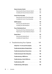
... System 147 Safety First-For You and Your System 147 Troubleshooting System Startup Failure 147 Troubleshooting External Connections 148 Troubleshooting the Video Subsystem 148 Troubleshooting a USB Device 148 Troubleshooting a Serial I/O Device 149 Troubleshooting a NIC 149 Troubleshooting a Wet System 150 8 Contents
... System 147 Safety First-For You and Your System 147 Troubleshooting System Startup Failure 147 Troubleshooting External Connections 148 Troubleshooting the Video Subsystem 148 Troubleshooting a USB Device 148 Troubleshooting a Serial I/O Device 149 Troubleshooting a NIC 149 Troubleshooting a Wet System 150 8 Contents
Hardware Owner's Manual
Page 9
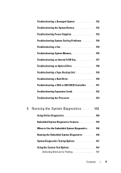
... 152 Troubleshooting the System Battery 152 Troubleshooting Power Supplies 153 Troubleshooting System Cooling Problems 154 Troubleshooting a Fan 154 Troubleshooting System Memory 155 Troubleshooting an Internal USB Key 157 Troubleshooting an Optical Drive 158 Troubleshooting a Tape Backup Unit 159 Troubleshooting a Hard Drive 160 Troubleshooting a SAS or SAS RAID Controller . . . . 161 Troubleshooting Expansion...
... 152 Troubleshooting the System Battery 152 Troubleshooting Power Supplies 153 Troubleshooting System Cooling Problems 154 Troubleshooting a Fan 154 Troubleshooting System Memory 155 Troubleshooting an Internal USB Key 157 Troubleshooting an Optical Drive 158 Troubleshooting a Tape Backup Unit 159 Troubleshooting a Hard Drive 160 Troubleshooting a SAS or SAS RAID Controller . . . . 161 Troubleshooting Expansion...
Hardware Owner's Manual
Page 14
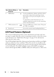
...if directed to signify when the system is turned off and can be turned on by the operating system's documentation. The ports are USB 2.0-compliant. See "LCD Status Messages" on the LCD panel. The LCD backlight lights blue during normal operating conditions and lights amber ... remains off if LCD messaging is operating correctly or when the system needs attention. Connects USB devices to indicate an error condition. Item Indicator, Button, or Icon Connector 8 NMI button 9 USB connectors (2) 10 Front bezel Description Used to troubleshoot software and device driver errors when using...
...if directed to signify when the system is turned off and can be turned on by the operating system's documentation. The ports are USB 2.0-compliant. See "LCD Status Messages" on the LCD panel. The LCD backlight lights blue during normal operating conditions and lights amber ... remains off if LCD messaging is operating correctly or when the system needs attention. Connects USB devices to indicate an error condition. Item Indicator, Button, or Icon Connector 8 NMI button 9 USB connectors (2) 10 Front bezel Description Used to troubleshoot software and device driver errors when using...
Hardware Owner's Manual
Page 20
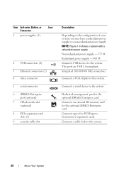
Item Indicator, Button, or Icon Connector 1 power supplies (2) 2 USB connectors (4) 3 Ethernet connectors (2) 4 video connector 5 serial connector 6 iDRAC6 Enterprise port (optional) 7 VFlash media slot (optional) 8 PCIe expansion card slots (5) 9 security cable slot Description Depending on ... management port for the optional iDRAC6 Enterprise card. Integrated 10/100/1000 NIC connectors. Connects up to the system. Generation 2 expansion cards. The ports are USB 2.0-compliant. Non-redundant power supply - 375 W Redundant power supply - 400 W Connects...
Item Indicator, Button, or Icon Connector 1 power supplies (2) 2 USB connectors (4) 3 Ethernet connectors (2) 4 video connector 5 serial connector 6 iDRAC6 Enterprise port (optional) 7 VFlash media slot (optional) 8 PCIe expansion card slots (5) 9 security cable slot Description Depending on ... management port for the optional iDRAC6 Enterprise card. Integrated 10/100/1000 NIC connectors. Connects up to the system. Generation 2 expansion cards. The ports are USB 2.0-compliant. Non-redundant power supply - 375 W Redundant power supply - 400 W Connects...
Hardware Owner's Manual
Page 24
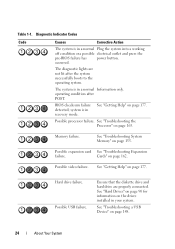
...mode. See "Troubleshooting the Processor" on page 162. Cards" on page 163. Table 1-1. occurred. BIOS checksum failure detected; Possible USB failure. operating condition after the system successfully boots to the operating system. Possible processor failure. See "Getting Help" on page 148.... 24 About Your System See "Troubleshooting a USB Device" on page 177. Possible expansion card See "Troubleshooting Expansion failure. See "Hard Drives" on page 90 for information on ...
...mode. See "Troubleshooting the Processor" on page 162. Cards" on page 163. Table 1-1. occurred. BIOS checksum failure detected; Possible USB failure. operating condition after the system successfully boots to the operating system. Possible processor failure. See "Getting Help" on page 148.... 24 About Your System See "Troubleshooting a USB Device" on page 177. Possible expansion card See "Troubleshooting Expansion failure. See "Hard Drives" on page 90 for information on ...
Hardware Owner's Manual
Page 34
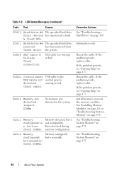
Table 1-2. E1A1D Control panel USB cable to the USB cable not control panel is missing or bad. E2010 Memory not detected. See "Troubleshooting System Memory" on page 155. the system. SAS cable A is detected. ...
Table 1-2. E1A1D Control panel USB cable to the USB cable not control panel is missing or bad. E2010 Memory not detected. See "Troubleshooting System Memory" on page 155. the system. SAS cable A is detected. ...
Hardware Owner's Manual
Page 42
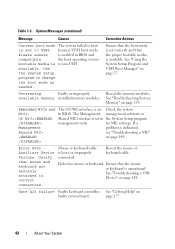
... Faulty keyboard controller; See "Using the System Setup Program and UEFI Boot Manager" on page 155. Mouse or keyboard cable is non-UEFI. See "Troubleshooting a USB Device" on faulty system board. See "Getting Help" on page 148. Please ensure compatible bootable media is indicated, see "Troubleshooting a NIC" on page 149. Table...
... Faulty keyboard controller; See "Using the System Setup Program and UEFI Boot Manager" on page 155. Mouse or keyboard cable is non-UEFI. See "Troubleshooting a USB Device" on faulty system board. See "Getting Help" on page 148. Please ensure compatible bootable media is indicated, see "Troubleshooting a NIC" on page 149. Table...
Hardware Owner's Manual
Page 43
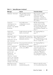
...detected at the See "Getting Help" on faulty system board page 177. Local keyboard may not work because all user accessible USB ports are disabled in manufacturing mode. About Your System 43 Invalid configuration information please run SETUP program. Keyboard controller failure Faulty ...keyboard controller; If operating locally, power cycle the system and enter system setup program to enable the USB port(s). Reboot to take the appropriate action to carry out the command. page 177. Keyboard data line failure Keyboard stuck key...
...detected at the See "Getting Help" on faulty system board page 177. Local keyboard may not work because all user accessible USB ports are disabled in manufacturing mode. About Your System 43 Invalid configuration information please run SETUP program. Keyboard controller failure Faulty ...keyboard controller; If operating locally, power cycle the system and enter system setup program to enable the USB port(s). Reboot to take the appropriate action to carry out the command. page 177. Keyboard data line failure Keyboard stuck key...
Hardware Owner's Manual
Page 45
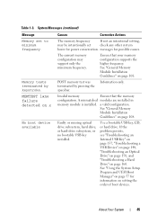
...memory configuration may be intentionally set to minimum frequency. Information only. If the problem persists, see "Troubleshooting an Internal USB Key" on page 157, "Troubleshooting a USB Device" on page 148, "Troubleshooting an Optical Drive" on page 158, and "Troubleshooting a Hard Drive" on setting... test was terminated by keystroke. Faulty or missing optical drive subsystem, hard drive, or hard-drive subsystem, or no bootable USB key installed. About Your System 45 MEMTEST lane failure detected on x No boot device available Causes Corrective Actions The memory frequency...
...memory configuration may be intentionally set to minimum frequency. Information only. If the problem persists, see "Troubleshooting an Internal USB Key" on page 157, "Troubleshooting a USB Device" on page 148, "Troubleshooting an Optical Drive" on page 158, and "Troubleshooting a Hard Drive" on setting... test was terminated by keystroke. Faulty or missing optical drive subsystem, hard drive, or hard-drive subsystem, or no bootable USB key installed. About Your System 45 MEMTEST lane failure detected on x No boot device available Causes Corrective Actions The memory frequency...

Hardware Owner's Manual
Page 47
...Drive" on page 158, or "Troubleshooting a Hard Drive" on page 160 for the appropriate drive(s) installed in socket. optical drive, or USB device, Ensure that the memory modules are or the requested sector is properly connected. specified SATA port is no device connected Information only. defective.... specified SATA port. single rank or dual rank DIMM in your system. Ensure that the the system could not find a SAS backplane, USB, particular sector on page 108. See "General Memory Module Installation Guidelines" on the disk, or SATA cables are installed in a valid ...
...Drive" on page 158, or "Troubleshooting a Hard Drive" on page 160 for the appropriate drive(s) installed in socket. optical drive, or USB device, Ensure that the memory modules are or the requested sector is properly connected. specified SATA port is no device connected Information only. defective.... specified SATA port. single rank or dual rank DIMM in your system. Ensure that the the system could not find a SAS backplane, USB, particular sector on page 108. See "General Memory Module Installation Guidelines" on the disk, or SATA cables are installed in a valid ...
Hardware Owner's Manual
Page 48
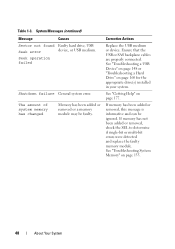
... the appropriate drive(s) installed in your system. System Messages (continued) Message Causes Sector not found Faulty hard drive, USB Seek error device, or USB medium. Corrective Actions Replace the USB medium or device. See "Troubleshooting a USB Device" on page 148 or "Troubleshooting a Hard Drive" on page 177. See "Troubleshooting System Memory" on page 155... single-bit or multi-bit errors were detected and replace the faulty memory module. Seek operation failed Shutdown failure General system error. Ensure that the USB or SAS backplane cables are properly connected.
... the appropriate drive(s) installed in your system. System Messages (continued) Message Causes Sector not found Faulty hard drive, USB Seek error device, or USB medium. Corrective Actions Replace the USB medium or device. See "Troubleshooting a USB Device" on page 148 or "Troubleshooting a Hard Drive" on page 177. See "Troubleshooting System Memory" on page 155... single-bit or multi-bit errors were detected and replace the faulty memory module. Seek operation failed Shutdown failure General system error. Ensure that the USB or SAS backplane cables are properly connected.
Hardware Owner's Manual
Page 54
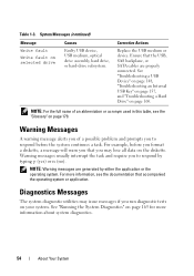
... you of an abbreviation or acronym used in this table, see the documentation that you run diagnostic tests on page 160. Ensure that the USB, SAS backplane, or SATA cables are generated by typing y (yes) or n (no). System Messages (continued) Message Write fault Write ... page 165 for more information, see the "Glossary" on the diskette. See "Running the System Diagnostics" on selected drive Causes Faulty USB device, USB medium, optical drive assembly, hard drive, or hard-drive subsystem. Warning messages usually interrupt the task and require you to respond by...
... you of an abbreviation or acronym used in this table, see the documentation that you run diagnostic tests on page 160. Ensure that the USB, SAS backplane, or SATA cables are generated by typing y (yes) or n (no). System Messages (continued) Message Write fault Write ... page 165 for more information, see the "Glossary" on the diskette. See "Running the System Diagnostics" on selected drive Causes Faulty USB device, USB medium, optical drive assembly, hard drive, or hard-drive subsystem. Warning messages usually interrupt the task and require you to respond by...
Hardware Owner's Manual
Page 63
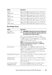
.... Boot Sequence Retry (Disabled default) If this field to SATA port C. Auto enables BIOS support for a USB flash drive. Use the up and down arrow keys to SATA port E. USB Flash Drive Emulation Type Determines the emulation type for the device attached to UEFI disables the Boot Sequence, Hard...-Disk Drive Sequence, and USB Flash Drive Emulation Type fields. Using the System Setup Program and UEFI Boot Manager 63 Off disables BIOS support for the device. Boot...
.... Boot Sequence Retry (Disabled default) If this field to SATA port C. Auto enables BIOS support for a USB flash drive. Use the up and down arrow keys to SATA port E. USB Flash Drive Emulation Type Determines the emulation type for the device attached to UEFI disables the Boot Sequence, Hard...-Disk Drive Sequence, and USB Flash Drive Emulation Type fields. Using the System Setup Program and UEFI Boot Manager 63 Off disables BIOS support for the device. Boot...
Hardware Owner's Manual
Page 64
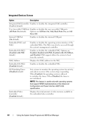
... Timer (Disabled default) Sets a timer to boot from the network. The NICs may also be accessed through the system's management controller. Internal USB Port (On default) Enables or disables the internal USB port. Integrated Devices Screen Option Description Integrated SAS Controller Enables or disables the integrated SAS controller. (Enabled default) User Accessible...
... Timer (Disabled default) Sets a timer to boot from the network. The NICs may also be accessed through the system's management controller. Internal USB Port (On default) Enables or disables the internal USB port. Integrated Devices Screen Option Description Integrated SAS Controller Enables or disables the integrated SAS controller. (Enabled default) User Accessible...
Hardware Owner's Manual
Page 69
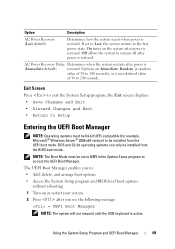
... the BIOS boot mode. The UEFI Boot Manager enables you see the following message: = UEFI Boot Manager NOTE: The system will not respond until the USB keyboard is active. NOTE: The Boot Mode must be 64-bit UEFI-compatible (for example, Microsoft® Windows Server® 2008 x64 version) to : •...
... the BIOS boot mode. The UEFI Boot Manager enables you see the following message: = UEFI Boot Manager NOTE: The system will not respond until the USB keyboard is active. NOTE: The Boot Mode must be 64-bit UEFI-compatible (for example, Microsoft® Windows Server® 2008 x64 version) to : •...

Hardware Owner's Manual
Page 124
...enabled by your warranty. See Figure 6-1. 124 Installing System Components Read and follow the safety instructions that is not authorized by Dell is not covered by the Internal USB Port option in the Integrated Devices screen of the card. 3 Press the card to lock it and pull the card from... the product. 1 Turn off the system, including any attached peripherals, and disconnect the system from the electrical outlet. 2 Open the system. The USB connector must be done by the online or telephone service and support team. Damage due to release it into the card slot on the module...
...enabled by your warranty. See Figure 6-1. 124 Installing System Components Read and follow the safety instructions that is not authorized by Dell is not covered by the Internal USB Port option in the Integrated Devices screen of the card. 3 Press the card to lock it and pull the card from... the product. 1 Turn off the system, including any attached peripherals, and disconnect the system from the electrical outlet. 2 Open the system. The USB connector must be done by the online or telephone service and support team. Damage due to release it into the card slot on the module...

Hardware Owner's Manual
Page 125
See Figure 3-21. 5 Close the system. Figure 3-21. 4 Insert the USB memory key into the USB connector. Removing or Installing a USB Memory Key 1 2 1 USB memory key 2 USB memory key connector Installing System Components 125 See "Entering the System Setup Program" on the system and attached peripherals. 9 Enter the System Setup program and verify that the USB key has been detected by the system. See "Closing the System" on page 86. 6 Place the system upright on a flat surface. 7 Reattach any peripherals and connect the system to an electrical outlet. 8 Turn on page 58.
See Figure 3-21. 5 Close the system. Figure 3-21. 4 Insert the USB memory key into the USB connector. Removing or Installing a USB Memory Key 1 2 1 USB memory key 2 USB memory key connector Installing System Components 125 See "Entering the System Setup Program" on the system and attached peripherals. 9 Enter the System Setup program and verify that the USB key has been detected by the system. See "Closing the System" on page 86. 6 Place the system upright on a flat surface. 7 Reattach any peripherals and connect the system to an electrical outlet. 8 Turn on page 58.
Hardware Owner's Manual
Page 148
...interface cabling from the system briefly and reconnect them from the system. 148 Troubleshooting Your System Troubleshooting External Connections Ensure that all attached USB devices and disconnect them . See "Using Online Diagnostics" on the opposite side of the system. b Connect the keyboard/mouse ... tests run successfully, the problem is resolved, restart the system, enter the System Setup program, and check if the nonfunctioning USB ports are securely attached to video hardware. If the problem is not related to the external connectors on your system. Troubleshooting ...
...interface cabling from the system briefly and reconnect them from the system. 148 Troubleshooting Your System Troubleshooting External Connections Ensure that all attached USB devices and disconnect them . See "Using Online Diagnostics" on the opposite side of the system. b Connect the keyboard/mouse ... tests run successfully, the problem is resolved, restart the system, enter the System Setup program, and check if the nonfunctioning USB ports are securely attached to video hardware. If the problem is not related to the external connectors on your system. Troubleshooting ...
Hardware Owner's Manual
Page 149
If all USB ports are enabled. If the problem persists, see "Getting Help" on page 177. Troubleshooting a NIC 1 Run the appropriate online diagnostic test. See "Using Online Diagnostics" ... controller. If your system and restoring the BIOS to the default settings. 4 Reconnect and power on each USB device one at a time. 5 If a device causes the same problem, power down the device, replace the USB cable, and power up the device. If the problem persists, replace the device. If the problem is...
If all USB ports are enabled. If the problem persists, see "Getting Help" on page 177. Troubleshooting a NIC 1 Run the appropriate online diagnostic test. See "Using Online Diagnostics" ... controller. If your system and restoring the BIOS to the default settings. 4 Reconnect and power on each USB device one at a time. 5 If a device causes the same problem, power down the device, replace the USB cable, and power up the device. If the problem persists, replace the device. If the problem is...


