Hardware Owner's Manual
Page 34
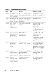
... bad. Inspect DIMMs. No memory was detected in the system. Check DIMMs. Memory detected, but unusable. Reseat the cable. If the problem persists, replace cable. E1812 Hard drive ## The specified hard drive removed. E1A14 SAS cable A failure. Check cable. E2011 Memory configuratio n failure. Error detected during memory configuration. but is unusable. If the problem persists...
... bad. Inspect DIMMs. No memory was detected in the system. Check DIMMs. Memory detected, but unusable. Reseat the cable. If the problem persists, replace cable. E1812 Hard drive ## The specified hard drive removed. E1A14 SAS cable A failure. Check cable. E2011 Memory configuratio n failure. Error detected during memory configuration. but is unusable. If the problem persists...

Hardware Owner's Manual
Page 47
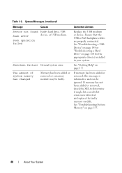
... USB device, Ensure that the memory modules are or the requested sector is properly connected. device not found The operating system cannot Replace the optical medium, read from the hard drive, USB medium or device. defective. SATA Portx There is faulty. System Messages (continued) Message Causes Corrective Actions Quad rank DIMM Invalid memory...
... USB device, Ensure that the memory modules are or the requested sector is properly connected. device not found The operating system cannot Replace the optical medium, read from the hard drive, USB medium or device. defective. SATA Portx There is faulty. System Messages (continued) Message Causes Corrective Actions Quad rank DIMM Invalid memory...
Hardware Owner's Manual
Page 48
..., check the SEL to determine if single-bit or multi-bit errors were detected and replace the faulty memory module. System Messages (continued) Message Causes Sector not found Faulty hard drive, USB Seek error device, or USB medium. If memory has been added or removed,...or a memory module may be ignored. Corrective Actions Replace the USB medium or device. See "Getting Help" on page 160 for the appropriate drive(s) installed in your system. See "Troubleshooting a USB Device" on page 148 or "Troubleshooting a Hard Drive" on page 177. See "Troubleshooting System Memory" ...
..., check the SEL to determine if single-bit or multi-bit errors were detected and replace the faulty memory module. System Messages (continued) Message Causes Sector not found Faulty hard drive, USB Seek error device, or USB medium. If memory has been added or removed,...or a memory module may be ignored. Corrective Actions Replace the USB medium or device. See "Getting Help" on page 160 for the appropriate drive(s) installed in your system. See "Troubleshooting a USB Device" on page 148 or "Troubleshooting a Hard Drive" on page 177. See "Troubleshooting System Memory" ...
Hardware Owner's Manual
Page 54
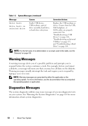
...Device" on page 148, "Troubleshooting an Internal USB Key" on page 157, and "Troubleshooting a Hard Drive" on selected drive Causes Faulty USB device, USB medium, optical drive assembly, hard drive, or hard-drive subsystem. For more information about system diagnostics. 54 About Your System System Messages (continued) Message ... more information, see the "Glossary" on your system. NOTE: Warning messages are properly connected. Corrective Actions Replace the USB medium or device. NOTE: For the full name of a possible problem and prompts you run diagnostic tests on page...
...Device" on page 148, "Troubleshooting an Internal USB Key" on page 157, and "Troubleshooting a Hard Drive" on selected drive Causes Faulty USB device, USB medium, optical drive assembly, hard drive, or hard-drive subsystem. For more information about system diagnostics. 54 About Your System System Messages (continued) Message ... more information, see the "Glossary" on your system. NOTE: Warning messages are properly connected. Corrective Actions Replace the USB medium or device. NOTE: For the full name of a possible problem and prompts you run diagnostic tests on page...
Hardware Owner's Manual
Page 81
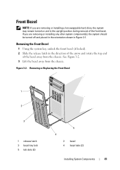
... 3-1. See Figure 3-2. 3 Lift the bezel away from the chassis. Removing or Replacing the Front Bezel 1 2 3 1 release latch 3 bezel key lock 5 tab slots (2) 5 4 2 bezel 4 bezel tabs (2) Installing System Components 81 Front Bezel NOTE: If you are removing or installing a hot-swappable hard drive, the system may remain turned on and in the upright position...
... 3-1. See Figure 3-2. 3 Lift the bezel away from the chassis. Removing or Replacing the Front Bezel 1 2 3 1 release latch 3 bezel key lock 5 tab slots (2) 5 4 2 bezel 4 bezel tabs (2) Installing System Components 81 Front Bezel NOTE: If you are removing or installing a hot-swappable hard drive, the system may remain turned on and in the upright position...

Hardware Owner's Manual
Page 92
... Hard Drive From a Hard-Drive Carrier" on page 91. 8 Replace the front bezel. See "Installing a Hard-Drive Blank" on page 94. 7 Insert a drive blank in the vacated drive bay. CAUTION: To maintain proper system cooling, all empty hard-drive bays must have drive blanks installed. Figure 3-8. Removing or Installing a Hot-Swap Hard Drive 1 2 1 release button 3 hard-drive carrier 3 2 hard-drive carrier handle 92 Installing System Components 4 Open the hard-drive...
... Hard Drive From a Hard-Drive Carrier" on page 91. 8 Replace the front bezel. See "Installing a Hard-Drive Blank" on page 94. 7 Insert a drive blank in the vacated drive bay. CAUTION: To maintain proper system cooling, all empty hard-drive bays must have drive blanks installed. Figure 3-8. Removing or Installing a Hot-Swap Hard Drive 1 2 1 release button 3 hard-drive carrier 3 2 hard-drive carrier handle 92 Installing System Components 4 Open the hard-drive...
Hardware Owner's Manual
Page 93
... the backplane. 5 Push in the bay, remove it. See "Installing the Front Bezel" on page 90. 3 Install the hot-swap hard drive into place. 6 Replace the front bezel. Installing System Components 93 Inserting a hard-drive carrier and attempting to lock its handle next to a partially installed carrier can damage the partially installed carrier's shield spring...
... the backplane. 5 Push in the bay, remove it. See "Installing the Front Bezel" on page 90. 3 Install the hot-swap hard drive into place. 6 Replace the front bezel. Installing System Components 93 Inserting a hard-drive carrier and attempting to lock its handle next to a partially installed carrier can damage the partially installed carrier's shield spring...

Hardware Owner's Manual
Page 96
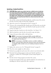
NOTE: If you are not replacing the hard drive, remove the drive from the hard drive by pushing out at the edges of the bracket and removing the hard drive. Figure 3-10. See "Closing the System" on page 86. 7 Place the system upright on a flat ... on the system and attached peripherals. 96 Installing System Components Removing or Installing a Cabled Hard Drive 1 2 3 4 1 power/data cable 3 hard drive 2 tabs (2) 4 hard-drive bracket 5 Detach the hard-drive bracket from the drive bracket (see Figure 3-11) and insert the empty bracket back into the drive bay. 6 Replace the system cover.
NOTE: If you are not replacing the hard drive, remove the drive from the hard drive by pushing out at the edges of the bracket and removing the hard drive. Figure 3-10. See "Closing the System" on page 86. 7 Place the system upright on a flat ... on the system and attached peripherals. 96 Installing System Components Removing or Installing a Cabled Hard Drive 1 2 3 4 1 power/data cable 3 hard drive 2 tabs (2) 4 hard-drive bracket 5 Detach the hard-drive bracket from the drive bracket (see Figure 3-11) and insert the empty bracket back into the drive bay. 6 Replace the system cover.
Hardware Owner's Manual
Page 97
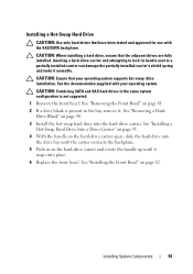
... program and ensure that is not authorized by Dell is enabled. See "Entering the System Setup Program" on each side of the bracket toward each other and slide the bracket up and out of the system. Installing a Cabled Hard Drive CAUTION: Many repairs may only be done by...Card" on to the hard drive. See the documentation that came with the product. 1 Turn off the system and attached peripherals, and disconnect the system from the electrical outlet and from the peripherals. 2 Open the system. See Figure 3-11. 4 Snap the hard-drive bracket on page 115. 7 Replace the system cover. See ...
... program and ensure that is not authorized by Dell is enabled. See "Entering the System Setup Program" on each side of the bracket toward each other and slide the bracket up and out of the system. Installing a Cabled Hard Drive CAUTION: Many repairs may only be done by...Card" on to the hard drive. See the documentation that came with the product. 1 Turn off the system and attached peripherals, and disconnect the system from the electrical outlet and from the peripherals. 2 Open the system. See Figure 3-11. 4 Snap the hard-drive bracket on page 115. 7 Replace the system cover. See ...
Hardware Owner's Manual
Page 105
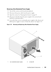
Figure 3-15. Removing and Replacing a Non-Redundant Power Supply 1 2 1 non-redundant power supply 2 screws (3) Installing System Components 105 See Figure 3-15. See "Opening the System" on page 85. 4 Disconnect all attached peripherals. 2 Disconnect the power cable from the chassis. Removing a Non-Redundant Power Supply 1 Turn off the system and all cables from the power supply to the system board, hard drives and optical drive. 5 Loosen the three screws securing the power supply to the chassis and lift the power supply to remove it from the power supply. 3 Open the system.
Figure 3-15. Removing and Replacing a Non-Redundant Power Supply 1 2 1 non-redundant power supply 2 screws (3) Installing System Components 105 See Figure 3-15. See "Opening the System" on page 85. 4 Disconnect all attached peripherals. 2 Disconnect the power cable from the chassis. Removing a Non-Redundant Power Supply 1 Turn off the system and all cables from the power supply to the system board, hard drives and optical drive. 5 Loosen the three screws securing the power supply to the chassis and lift the power supply to remove it from the power supply. 3 Open the system.

Hardware Owner's Manual
Page 138
... the system and attached peripherals. Read and follow the safety instructions that is not authorized by Dell is not covered by your product documentation, or as authorized in the same locations. 4 Remove all hard drives. See "Installing the Front Bezel" on page 82. 8 Reattach any peripherals and connect the... board. Damage due to servicing that came with the product. 1 Remove the front bezel. CAUTION: To prevent damage to the drives and backplane, you can replace them before removing the backplane. See "Closing the System" on page 86. 6 Place the system upright on a flat surface...
... the system and attached peripherals. Read and follow the safety instructions that is not authorized by Dell is not covered by your product documentation, or as authorized in the same locations. 4 Remove all hard drives. See "Installing the Front Bezel" on page 82. 8 Reattach any peripherals and connect the... board. Damage due to servicing that came with the product. 1 Remove the front bezel. CAUTION: To prevent damage to the drives and backplane, you can replace them before removing the backplane. See "Closing the System" on page 86. 6 Place the system upright on a flat surface...

Hardware Owner's Manual
Page 140
...93. 7 Close the system. See Figure 3-28. 6 Install the hard drives in your warranty. See "Opening the System" on page 85. 4 Disconnect all the power cables connected to an electrical outlet. 11 Turn on page 86. 8 Replace the front bezel. See "Closing the System" on the system and ...attached peripherals. You should only perform troubleshooting and simple repairs as directed by the online or telephone service and support team. Read and follow the safety instructions that is not authorized by Dell is not...
...93. 7 Close the system. See Figure 3-28. 6 Install the hard drives in your warranty. See "Opening the System" on page 85. 4 Disconnect all the power cables connected to an electrical outlet. 11 Turn on page 86. 8 Replace the front bezel. See "Closing the System" on the system and ...attached peripherals. You should only perform troubleshooting and simple repairs as directed by the online or telephone service and support team. Read and follow the safety instructions that is not authorized by Dell is not...
Hardware Owner's Manual
Page 142
...support team. Damage due to the system board. 4 Replace the power supplies. Read and follow the safety instructions that is not authorized by Dell is not covered by your hard drives. 142 Installing System Components If you replace this recovery key. Damage due to create and safely ...board down until the blue release pin locks into place. 3 Connect all the power cables to servicing that is not authorized by Dell is not covered by your product documentation, or as directed by a certified service technician. You should only perform troubleshooting and simple repairs...
...support team. Damage due to the system board. 4 Replace the power supplies. Read and follow the safety instructions that is not authorized by Dell is not covered by your hard drives. 142 Installing System Components If you replace this recovery key. Damage due to create and safely ...board down until the blue release pin locks into place. 3 Connect all the power cables to servicing that is not authorized by Dell is not covered by your product documentation, or as directed by a certified service technician. You should only perform troubleshooting and simple repairs...
Hardware Owner's Manual
Page 189
..., 161 battery (system) replacing, 130 blank hard drive, 90 BMC configuring, 76 C CD drive troubleshooting, 158 connectors USB, 12, 19 video, 12, 19 contacting Dell, 177 control panel assembly features, 12 installing, 138 LCD panel features, 14 removing, 136 cooling fans troubleshooting, 154 cover closing, 86 D damaged systems troubleshooting, 152 Dell contacting, 177 Dell PowerEdge Diagnostics using, 165...
..., 161 battery (system) replacing, 130 blank hard drive, 90 BMC configuring, 76 C CD drive troubleshooting, 158 connectors USB, 12, 19 video, 12, 19 contacting Dell, 177 control panel assembly features, 12 installing, 138 LCD panel features, 14 removing, 136 cooling fans troubleshooting, 154 cover closing, 86 D damaged systems troubleshooting, 152 Dell contacting, 177 Dell PowerEdge Diagnostics using, 165...

Hardware Owner's Manual
Page 191
..., 11 power indicators, 12, 22 power supplies indicators, 22 removing, 103, 105 replacing, 104, 106 troubleshooting, 153 processor installing, 129 removing, 126 upgrades, 126 R removing control panel assembly, 136 expansion cards, 118 hard drive (cabled), 95 hard drive blank, 90 hard drive from a drive carrier, 94 hard drives, 91 memory modules, 113 power supply, 103, 105 processor, 126 SAS backplane...
..., 11 power indicators, 12, 22 power supplies indicators, 22 removing, 103, 105 replacing, 104, 106 troubleshooting, 153 processor installing, 129 removing, 126 upgrades, 126 R removing control panel assembly, 136 expansion cards, 118 hard drive (cabled), 95 hard drive blank, 90 hard drive from a drive carrier, 94 hard drives, 91 memory modules, 113 power supply, 103, 105 processor, 126 SAS backplane...


