Getting Started Guide
Page 9
...This service may not be offered in this guide or if the system does not perform as expected, see your Hardware Owner's Manual. Dell™ offers comprehensive hardware training and certification. Technical Specifications Processor Processor type One quad-core Intel® Xeon® processor Expansion Bus ... Slot4: PCIe x1 (x1 routing) half-length Slot5: PCIe x1 (x1 routing) half-length 800-MHz, 1066-MHz, or 1333-MHz DDR3 registered or unbuffered Error Correcting Code (ECC) DIMMs. Six 240-pin 1 GB, 2 GB, 4 GB, or 8 GB 1 GB 32 GB Getting Started With Your System 7 Obtaining Technical ...
...This service may not be offered in this guide or if the system does not perform as expected, see your Hardware Owner's Manual. Dell™ offers comprehensive hardware training and certification. Technical Specifications Processor Processor type One quad-core Intel® Xeon® processor Expansion Bus ... Slot4: PCIe x1 (x1 routing) half-length Slot5: PCIe x1 (x1 routing) half-length 800-MHz, 1066-MHz, or 1333-MHz DDR3 registered or unbuffered Error Correcting Code (ECC) DIMMs. Six 240-pin 1 GB, 2 GB, 4 GB, or 8 GB 1 GB 32 GB Getting Started With Your System 7 Obtaining Technical ...
Hardware Owner's Manual
Page 13
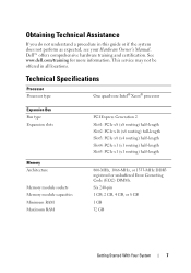
... When powering on the amount of whether the system has been powered on page 23. Provides system ID, status information, and system error messages. Allows you to navigate the control panel LCD menu. 6 System identification button 7 Power-on indicator, power button The identification ...LCD menu buttons Description LED panel - The four diagnostic indicator lights display error codes during normal system operation. The LCD lights amber when the system needs attention, and the LCD panel displays an error code followed by descriptive text. When the button is connected to locate a ...
... When powering on the amount of whether the system has been powered on page 23. Provides system ID, status information, and system error messages. Allows you to navigate the control panel LCD menu. 6 System identification button 7 Power-on indicator, power button The identification ...LCD menu buttons Description LED panel - The four diagnostic indicator lights display error codes during normal system operation. The LCD lights amber when the system needs attention, and the LCD panel displays an error code followed by descriptive text. When the button is connected to locate a ...
Hardware Owner's Manual
Page 14
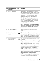
... only if directed to do so by qualified support personnel or by pressing the Select button on page 25 for information about specific status codes. When the system is in standby mode, the LCD backlight is operating correctly or when the system needs attention. Covers the system's ...front-loading hard drives. See "LCD Status Messages" on the LCD panel. Connects USB devices to indicate an error condition. Item Indicator, Button, or Icon Connector 8 NMI button 9 USB connectors (2) 10 Front bezel Description Used to troubleshoot software and device driver...
... only if directed to do so by qualified support personnel or by pressing the Select button on page 25 for information about specific status codes. When the system is in standby mode, the LCD backlight is operating correctly or when the system needs attention. Covers the system's ...front-loading hard drives. See "LCD Status Messages" on the LCD panel. Connects USB devices to indicate an error condition. Item Indicator, Button, or Icon Connector 8 NMI button 9 USB connectors (2) 10 Front bezel Description Used to troubleshoot software and device driver...
Hardware Owner's Manual
Page 23
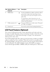
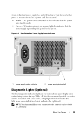
... switch Diagnostic Lights (Optional) The four diagnostic indicator lights on , a green light also indicates that the power supply is on the system front panel display error codes during system startup. When the system is providing DC power to the system. A highlighted circle indicates the light is off. AC power is equipped with...
... switch Diagnostic Lights (Optional) The four diagnostic indicator lights on , a green light also indicates that the power supply is on the system front panel display error codes during system startup. When the system is providing DC power to the system. A highlighted circle indicates the light is off. AC power is equipped with...
Hardware Owner's Manual
Page 25
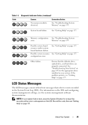
...page 177. See "Getting Help" on page 155. Memory configuration See "Troubleshooting System error. Possible system resource See "Getting Help" on page 177. About Your System 25 Table 1-1. Diagnostic Indicator Codes (continued) Code Causes No memory modules detected. See "Getting Help" on page 177. LCD Status ...see "Getting Help" on the LCD. Ensure that refer to boot, press the System ID button for at least five seconds until an error code appears on page 177. If the problem persists, see "Getting Help" on page 155. See "Troubleshooting Your System" on page 147...
...page 177. See "Getting Help" on page 155. Memory configuration See "Troubleshooting System error. Possible system resource See "Getting Help" on page 177. About Your System 25 Table 1-1. Diagnostic Indicator Codes (continued) Code Causes No memory modules detected. See "Getting Help" on page 177. LCD Status ...see "Getting Help" on the LCD. Ensure that refer to boot, press the System ID button for at least five seconds until an error code appears on page 177. If the problem persists, see "Getting Help" on page 155. See "Troubleshooting Your System" on page 147...
Hardware Owner's Manual
Page 26
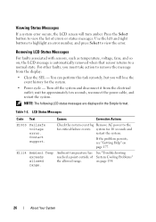
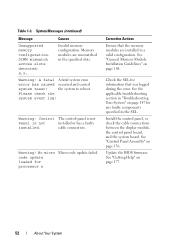
... buttons to highlight an error number, and press Select to view the list of the allowed range. Turn off the system and disconnect it from the display: • Clear the SEL - For other faults, you will turn amber. LCD Status Messages Code Text Causes Corrective Actions... E1000 Failsafe voltage error. wait for 10 seconds and restart the system. system for approximately ten seconds, reconnect the power cable, and restart the...
... buttons to highlight an error number, and press Select to view the list of the allowed range. Turn off the system and disconnect it from the display: • Clear the SEL - For other faults, you will turn amber. LCD Status Messages Code Text Causes Corrective Actions... E1000 Failsafe voltage error. wait for 10 seconds and restart the system. system for approximately ten seconds, reconnect the power cable, and restart the...
Hardware Owner's Manual
Page 28
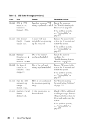
..." on page 177. E122E On-board regulator failed. Remove AC power to the system for 10 seconds and restart the system. LCD Status Messages (continued) Code Text Causes Corrective Actions E122A CPU # VTT Regulator failure. Call support. Remove AC power to the system for additional scrolling messages. If the problem persists.... RPM of fan is outside of the memory Regulator # regulators has failed. Reseat DIMMs. Reseat the memory modules. Check fan. E1410 System Fatal A fatal system error has Error been detected. Table 1-2. Check LCD for 10 seconds and restart the system.
..." on page 177. E122E On-board regulator failed. Remove AC power to the system for 10 seconds and restart the system. LCD Status Messages (continued) Code Text Causes Corrective Actions E122A CPU # VTT Regulator failure. Call support. Remove AC power to the system for additional scrolling messages. If the problem persists.... RPM of fan is outside of the memory Regulator # regulators has failed. Reseat DIMMs. Reseat the memory modules. Check fan. E1410 System Fatal A fatal system error has Error been detected. Table 1-2. Check LCD for 10 seconds and restart the system.

Hardware Owner's Manual
Page 29
...has reported a processor protocol error. If the problem persists, see "Getting Help" on page 154. E1420 CPU Bus The system BIOS has parity error. If the problem persists,...Check CPU is out exceeding of acceptable range. Check configuration. E141F CPU # protocol error. an unsupported See "Troubleshooting the configuration. Remove AC power to the system for ...Check temperature range. CPU heatsink. unsupported ation. reported a processor Power cycle bus parity error. See "Troubleshooting the Processor" on page 163 and "Troubleshooting System Cooling Problems" on...
...has reported a processor protocol error. If the problem persists, see "Getting Help" on page 154. E1420 CPU Bus The system BIOS has parity error. If the problem persists,...Check CPU is out exceeding of acceptable range. Check configuration. E141F CPU # protocol error. an unsupported See "Troubleshooting the configuration. Remove AC power to the system for ...Check temperature range. CPU heatsink. unsupported ation. reported a processor Power cycle bus parity error. See "Troubleshooting the Processor" on page 163 and "Troubleshooting System Cooling Problems" on...
Hardware Owner's Manual
Page 30
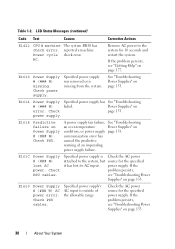
... Power Supply # (### W) lost its AC input. Check PSU cables. LCD Status Messages (continued) Code Text Causes Corrective Actions E1422 CPU # machine The system BIOS has check error. If the problem persists, see "Troubleshooting Power Supplies" on page 153. See "Troubleshooting Power Supplies"... the problem persists, see "Troubleshooting Power Supplies" on page 153. E1610 Power Supply # (### W) missing. E1618 Predictive failure on error. Specified power supply's AC input is outside of an impending power supply failure. Remove AC power to the system, but source for...
... Power Supply # (### W) lost its AC input. Check PSU cables. LCD Status Messages (continued) Code Text Causes Corrective Actions E1422 CPU # machine The system BIOS has check error. If the problem persists, see "Troubleshooting Power Supplies" on page 153. See "Troubleshooting Power Supplies"... the problem persists, see "Troubleshooting Power Supplies" on page 153. E1610 Power Supply # (### W) missing. E1618 Predictive failure on error. Specified power supply's AC input is outside of an impending power supply failure. Remove AC power to the system, but source for...
Hardware Owner's Manual
Page 31
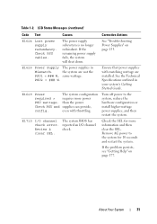
... restart the system. See "Troubleshooting Power Supplies" on page 177. Turn off power to the system for more power PSU wattage. LCD Status Messages (continued) Code Text Causes Corrective Actions E1624 Lost power supply redundancy. About Your System 31 Check the SEL for 10 seconds and restart the system. The power... Technical Specifications outlined in Mismatch. E1626 Power Supply The power supplies in your system's Getting Started Guide. The system BIOS has reported an I /O channel check error.
... restart the system. See "Troubleshooting Power Supplies" on page 177. Turn off power to the system for more power PSU wattage. LCD Status Messages (continued) Code Text Causes Corrective Actions E1624 Lost power supply redundancy. About Your System 31 Check the SEL for 10 seconds and restart the system. The power... Technical Specifications outlined in Mismatch. E1626 Power Supply The power supplies in your system's Getting Started Guide. The system BIOS has reported an I /O channel check error.
Hardware Owner's Manual
Page 32
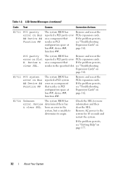
... BIOS has Remove and reseat the reported a PCI parity error PCIe expansion cards. LCD Status Messages (continued) Code Text Causes Corrective Actions E1711 PCI parity error on Slot #. see "Troubleshooting configuration space at bus ##, device ##, function ##. been an error in the specified slot. PCI parity error on Bus ## Device ## Function ## The system BIOS has Remove...
... BIOS has Remove and reseat the reported a PCI parity error PCIe expansion cards. LCD Status Messages (continued) Code Text Causes Corrective Actions E1711 PCI parity error on Slot #. see "Troubleshooting configuration space at bus ##, device ##, function ##. been an error in the specified slot. PCI parity error on Bus ## Device ## Function ## The system BIOS has Remove...
Hardware Owner's Manual
Page 33
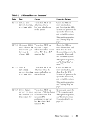
... "Getting Help" on page 177. If the problem persists, see "Getting Help" on page 177. Table 1-2. LCD Status Messages (continued) Code Text Causes Corrective Actions E1715 Fatal I/O The system BIOS has Error. Remove AC power to the system for 10 seconds, and restart the system. E1716 Chipset IERR Bus ## Dev ## Function ##. Review...
... "Getting Help" on page 177. If the problem persists, see "Getting Help" on page 177. Table 1-2. LCD Status Messages (continued) Code Text Causes Corrective Actions E1715 Fatal I/O The system BIOS has Error. Remove AC power to the system for 10 seconds, and restart the system. E1716 Chipset IERR Bus ## Dev ## Function ##. Review...
Hardware Owner's Manual
Page 34
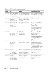
... cable. Check connection. SAS cable A is not configurable. Reseat the cable. Table 1-2. has been removed from Check drive. Check cable. Error detected during memory configuration. but is detected. If the problem persists, see "Getting Help" on page 177. Install memory or reseat the ... Memory Modules" on page 111 or "Troubleshooting System Memory" on page 155. 34 About Your System LCD Status Messages (continued) Code Text Causes E1810 Hard drive ## The specified hard drive fault. E2010 Memory not detected. E1A1D Control panel USB cable to the ...
... cable. Check connection. SAS cable A is not configurable. Reseat the cable. Table 1-2. has been removed from Check drive. Check cable. Error detected during memory configuration. but is detected. If the problem persists, see "Getting Help" on page 177. Install memory or reseat the ... Memory Modules" on page 111 or "Troubleshooting System Memory" on page 155. 34 About Your System LCD Status Messages (continued) Code Text Causes E1810 Hard drive ## The specified hard drive fault. E2010 Memory not detected. E1A1D Control panel USB cable to the ...
Hardware Owner's Manual
Page 35
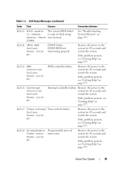
... AC power to the system for 10 seconds and restart the system. DIMMs. See "Troubleshooting System Memory" on page 177. E2018 Programmable Timer error. LCD Status Messages (continued) Code Text Causes Corrective Actions E2013 BIOS unable The system BIOS failed to shadow to the system for 10 seconds and restart the system...
... AC power to the system for 10 seconds and restart the system. DIMMs. See "Troubleshooting System Memory" on page 177. E2018 Programmable Timer error. LCD Status Messages (continued) Code Text Causes Corrective Actions E2013 BIOS unable The system BIOS failed to shadow to the system for 10 seconds and restart the system...
Hardware Owner's Manual
Page 36
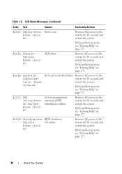
Parity error. SIO failure. If the problem persists, see "Getting Help" on page 177. Remove AC power to the system for 10 seconds and restart the system. ... AC power to the system for 10 seconds and restart the system. Power cycle AC. E201B Keyboard Controller error. Keyboard controller failure. test failure. LCD Status Messages (continued) Code Text Causes Corrective Actions E2019 Parity error. If the problem persists, see "Getting Help" on page 177. E201D Shutdown test BIOS shutdown failure. Power...
Parity error. SIO failure. If the problem persists, see "Getting Help" on page 177. Remove AC power to the system for 10 seconds and restart the system. ... AC power to the system for 10 seconds and restart the system. Power cycle AC. E201B Keyboard Controller error. Keyboard controller failure. test failure. LCD Status Messages (continued) Code Text Causes Corrective Actions E2019 Parity error. If the problem persists, see "Getting Help" on page 177. E201D Shutdown test BIOS shutdown failure. Power...
Hardware Owner's Manual
Page 37
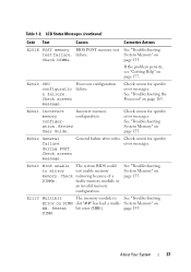
LCD Status Messages (continued) Code Text Causes Corrective Actions E201E POST memory BIOS POST memory test See "Troubleshooting test failure. E2020 CPU configuratio n failure. Check screen for specific error messages. E2021 Incorrect Incorrect memory memory configuration. ation. Review User Guide. ...module or an invalid memory configuration. page 155. failure. Check screen message. Processor configuration failure. Check screen for specific error messages. General failure after video. E2023 BIOS unable The system BIOS could to mirror not enable memory memory. See ...
LCD Status Messages (continued) Code Text Causes Corrective Actions E201E POST memory BIOS POST memory test See "Troubleshooting test failure. E2020 CPU configuratio n failure. Check screen for specific error messages. E2021 Incorrect Incorrect memory memory configuration. ation. Review User Guide. ...module or an invalid memory configuration. page 155. failure. Check screen message. Processor configuration failure. Check screen for specific error messages. General failure after video. E2023 BIOS unable The system BIOS could to mirror not enable memory memory. See ...

Hardware Owner's Manual
Page 38
... power to log any more SBEs If the problem persists, until the system is full of the mirror has had too many errors. The SEL is see "Troubleshooting System Memory" on page 155. Reseat DIMM. Check SEL to the disabled memory mirroring system ...represents the memory module pair implicated by the BIOS. The system BIOS has Remove AC power to review all Errors. Check chassis cover. LCD overflow message. LCD Status Messages (continued) Code Text Causes Corrective Actions E2111 SBE log disabled on the memory module page 155. "##" represents System Memory" on...
... power to log any more SBEs If the problem persists, until the system is full of the mirror has had too many errors. The SEL is see "Troubleshooting System Memory" on page 155. Reseat DIMM. Check SEL to the disabled memory mirroring system ...represents the memory module pair implicated by the BIOS. The system BIOS has Remove AC power to review all Errors. Check chassis cover. LCD overflow message. LCD Status Messages (continued) Code Text Causes Corrective Actions E2111 SBE log disabled on the memory module page 155. "##" represents System Memory" on...
Hardware Owner's Manual
Page 52
...modules are installed in the specified slots. the system to reboot. No micro Micro code update failed. code update loaded for processor n Corrective Actions Ensure that was logged during the error. See "General Memory Module Installation Guidelines" on page 136. DIMM mismatch across slots...Help" on page 147 for information that the memory modules are mismatched in a valid configuration. Warning: A fatal A fatal system error error has caused occurred and caused system reset! cable connection. Check the SEL for any faulty components specified in the SEL. Install the...
...modules are installed in the specified slots. the system to reboot. No micro Micro code update failed. code update loaded for processor n Corrective Actions Ensure that was logged during the error. See "General Memory Module Installation Guidelines" on page 136. DIMM mismatch across slots...Help" on page 147 for information that the memory modules are mismatched in a valid configuration. Warning: A fatal A fatal system error error has caused occurred and caused system reset! cable connection. Check the SEL for any faulty components specified in the SEL. Install the...
Hardware Owner's Manual
Page 185
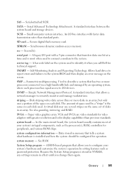
Serial-attached SCSI. A bar code label on each disk used. SMP - SNMP - Disk striping...system configuration information - SD card - Symmetric multiprocessing. Super video graphics array. Glossary 185 Allows hard drives to report errors and failures to identify it when you change them again. A legacy I /O bus interface with faster data transmission ...is installed and how the system should be configured for technical support. Data stored in effect until you call Dell for operation. SAS - A standard interface that tells a system what hardware is stored in NVRAM, any ...
Serial-attached SCSI. A bar code label on each disk used. SMP - SNMP - Disk striping...system configuration information - SD card - Symmetric multiprocessing. Super video graphics array. Glossary 185 Allows hard drives to report errors and failures to identify it when you change them again. A legacy I /O bus interface with faster data transmission ...is installed and how the system should be configured for technical support. Data stored in effect until you call Dell for operation. SAS - A standard interface that tells a system what hardware is stored in NVRAM, any ...


