Hardware Owner's Manual
Page 4
... Manager 57 Choosing the System Boot Mode 57 Entering the System Setup Program 58 Responding to Error Messages 58 Using the System Setup Program Navigation Keys 58 System Setup Options 59 Main Screen 59 Memory Settings Screen 61 Processor Settings Screen 62 SATA Settings Screen 62 Boot Settings Screen 63 Integrated... (Optional 66 Power Management Screen 66 System Security Screen 67 Exit Screen 69 Entering the UEFI Boot Manager 69 Using the UEFI Boot Manager Navigation Keys 70 UEFI Boot Manager Screen 70 UEFI Boot Settings Screen 71 System Utilities Screen 71 4 Contents
... Manager 57 Choosing the System Boot Mode 57 Entering the System Setup Program 58 Responding to Error Messages 58 Using the System Setup Program Navigation Keys 58 System Setup Options 59 Main Screen 59 Memory Settings Screen 61 Processor Settings Screen 62 SATA Settings Screen 62 Boot Settings Screen 63 Integrated... (Optional 66 Power Management Screen 66 System Security Screen 67 Exit Screen 69 Entering the UEFI Boot Manager 69 Using the UEFI Boot Manager Navigation Keys 70 UEFI Boot Manager Screen 70 UEFI Boot Settings Screen 71 System Utilities Screen 71 4 Contents
Hardware Owner's Manual
Page 9
... Troubleshooting the System Battery 152 Troubleshooting Power Supplies 153 Troubleshooting System Cooling Problems 154 Troubleshooting a Fan 154 Troubleshooting System Memory 155 Troubleshooting an Internal USB Key 157 Troubleshooting an Optical Drive 158 Troubleshooting a Tape Backup Unit 159 Troubleshooting a Hard Drive 160 Troubleshooting a SAS or SAS RAID Controller . . . . 161 Troubleshooting Expansion Cards...
... Troubleshooting the System Battery 152 Troubleshooting Power Supplies 153 Troubleshooting System Cooling Problems 154 Troubleshooting a Fan 154 Troubleshooting System Memory 155 Troubleshooting an Internal USB Key 157 Troubleshooting an Optical Drive 158 Troubleshooting a Tape Backup Unit 159 Troubleshooting a Hard Drive 160 Troubleshooting a SAS or SAS RAID Controller . . . . 161 Troubleshooting Expansion Cards...
Hardware Owner's Manual
Page 43
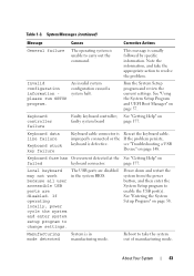
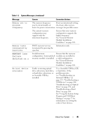
... out the command. page 177. See "Using the System Setup Program and UEFI Boot Manager" on failed keyboard connector. Keyboard data line failure Keyboard stuck key failure Keyboard cable connector is improperly connected or the keyboard is usually followed by specific information. The USB ports are disabled. Keyboard fuse has Overcurrent...
... out the command. page 177. See "Using the System Setup Program and UEFI Boot Manager" on failed keyboard connector. Keyboard data line failure Keyboard stuck key failure Keyboard cable connector is improperly connected or the keyboard is usually followed by specific information. The USB ports are disabled. Keyboard fuse has Overcurrent...
Hardware Owner's Manual
Page 45
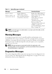
...The current memory configuration may be intentionally set to minimum frequency. a valid configuration. If the problem persists, see "Troubleshooting an Internal USB Key" on page 157, "Troubleshooting a USB Device" on page 148, "Troubleshooting an Optical Drive" on page 158, and "Troubleshooting a Hard... drive subsystem, hard drive, or hard-drive subsystem, or no bootable USB key installed. POST memory test was terminated by keystroke. messages for information on page 160. Use a bootable USB key, CD, or hard drive. Table 1-3. System Messages (continued) Message Memory ...
...The current memory configuration may be intentionally set to minimum frequency. a valid configuration. If the problem persists, see "Troubleshooting an Internal USB Key" on page 157, "Troubleshooting a USB Device" on page 148, "Troubleshooting an Optical Drive" on page 158, and "Troubleshooting a Hard... drive subsystem, hard drive, or hard-drive subsystem, or no bootable USB key installed. POST memory test was terminated by keystroke. messages for information on page 160. Use a bootable USB key, CD, or hard drive. Table 1-3. System Messages (continued) Message Memory ...
Hardware Owner's Manual
Page 54
... issue messages if you to respond by either the application or the operating system. See "Troubleshooting a USB Device" on page 148, "Troubleshooting an Internal USB Key" on page 157, and "Troubleshooting a Hard Drive" on selected drive Causes Faulty USB device, USB medium, optical drive assembly, hard drive, or hard-drive subsystem...
... issue messages if you to respond by either the application or the operating system. See "Troubleshooting a USB Device" on page 148, "Troubleshooting an Internal USB Key" on page 157, and "Troubleshooting a Hard Drive" on selected drive Causes Faulty USB device, USB medium, optical drive assembly, hard drive, or hard-drive subsystem...
Hardware Owner's Manual
Page 58
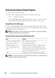
Responding to Error Messages If an error message appears while the system is normal for correcting errors. Using the System Setup Program Navigation Keys Keys Up arrow or Down arrow or Spacebar, Entering the System Setup Program 1 Turn on page 39 for an explanation of the message. NOTE: After installing a ...
Responding to Error Messages If an error message appears while the system is normal for correcting errors. Using the System Setup Program Navigation Keys Keys Up arrow or Down arrow or Spacebar, Entering the System Setup Program 1 Turn on page 39 for an explanation of the message. NOTE: After installing a ...
Hardware Owner's Manual
Page 60
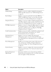
Displays a screen to 84-key keyboards). 60 Using the System Setup Program and UEFI Boot Manager For BIOS boot mode, you to manage power usage of the integrated devices on ... Communication Screen" on the PCI bus, and any installed expansion card that requires an IRQ. Enables you can also specify the boot devices. or 102-key keyboards (does not apply to specify the boot mode (BIOS or UEFI). Displays a screen to change the IRQ assigned to configure the system password and...
Displays a screen to 84-key keyboards). 60 Using the System Setup Program and UEFI Boot Manager For BIOS boot mode, you to manage power usage of the integrated devices on ... Communication Screen" on the PCI bus, and any installed expansion card that requires an IRQ. Enables you can also specify the boot devices. or 102-key keyboards (does not apply to specify the boot mode (BIOS or UEFI). Displays a screen to change the IRQ assigned to configure the system password and...
Hardware Owner's Manual
Page 63
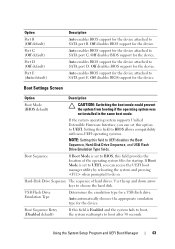
... UEFI. If the system operating system supports Unified Extensible Firmware Interface, you can set to choose the hard disk. Use the up and down arrow keys to BIOS, this field is set this field to SATA port D. Auto automatically chooses the appropriate emulation type for the device. Hard-Disk Drive Sequence...
... UEFI. If the system operating system supports Unified Extensible Firmware Interface, you can set to choose the hard disk. Use the up and down arrow keys to BIOS, this field is set this field to SATA port D. Auto automatically chooses the appropriate emulation type for the device. Hard-Disk Drive Sequence...

Hardware Owner's Manual
Page 65
... used for a given device, or select Default to allow the BIOS to the external serial connector. PCI IRQ Assignment Screen Option Description Use the and keys to manually select an IRQ for console redirection. External Serial Connector Specifies whether Serial Device1, Serial Device2, (Serial Device1 default) or Remote Access Device has...
... used for a given device, or select Default to allow the BIOS to the external serial connector. PCI IRQ Assignment Screen Option Description Use the and keys to manually select an IRQ for console redirection. External Serial Connector Specifies whether Serial Device1, Serial Device2, (Serial Device1 default) or Remote Access Device has...

Hardware Owner's Manual
Page 68
...the button can still turn on . Pressing this option. The No Change state initiates no action. When set to Off. Back up the TPM keys prior to the operating system and results in the TPM. NOTE: You can only turn on the system by the operating system's documentation. The operational...of the TPM remains unchanged (all user settings for the TPM are cleared. CAUTION: Clearing the TPM will lose all encryption keys in data loss if the encryption keys cannot be restored. On an ACPI-compliant operating system, the system performs an orderly shutdown before power is set to Off....
...the button can still turn on . Pressing this option. The No Change state initiates no action. When set to Off. Back up the TPM keys prior to the operating system and results in the TPM. NOTE: You can only turn on the system by the operating system's documentation. The operational...of the TPM remains unchanged (all user settings for the TPM are cleared. CAUTION: Clearing the TPM will lose all encryption keys in data loss if the encryption keys cannot be restored. On an ACPI-compliant operating system, the system performs an orderly shutdown before power is set to Off....

Hardware Owner's Manual
Page 70
...-add a boot device, press to refresh the list of available boot options (marked with the next item in a field. Using the UEFI Boot Manager Navigation Keys Keys Up arrow Down arrow Spacebar, Action Moves to and highlights the next field. Cycles through the settings in the boot order until the boot is...
...-add a boot device, press to refresh the list of available boot options (marked with the next item in a field. Using the UEFI Boot Manager Navigation Keys Keys Up arrow Down arrow Spacebar, Action Moves to and highlights the next field. Cycles through the settings in the boot order until the boot is...
Hardware Owner's Manual
Page 72
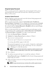
... system starts and only those with the password have full use up to Enabled. If Locked, you can use of the system. Certain key combinations are invalid and if you type, placeholders appear in the enabled position, System Password is Not Enabled and Password Status is Unlocked....Before assigning a system password, enter the System Setup program and check the System Password option. To erase a character, press or the left-arrow key. Exit the System Setup program and begin using your password. Using the System Password When a system password is not case-sensitive. The password ...
... system starts and only those with the password have full use up to Enabled. If Locked, you can use of the system. Certain key combinations are invalid and if you type, placeholders appear in the enabled position, System Password is Not Enabled and Password Status is Unlocked....Before assigning a system password, enter the System Setup program and check the System Password option. To erase a character, press or the left-arrow key. Exit the System Setup program and begin using your password. Using the System Password When a system password is not case-sensitive. The password ...
Hardware Owner's Manual
Page 74
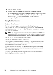
... the System Setup Program and UEFI Boot Manager 4 Type the system password. 5 Confirm that Not Enabled is displayed for the System Password, press the key combination to restart the system, and repeat step 1 to step 5. To assign a setup password, highlight the Setup Password option and press the or... key. If Enabled is displayed for the System Password. NOTE: The setup password can be used as the system password. You can assign a setup password...
... the System Setup Program and UEFI Boot Manager 4 Type the system password. 5 Confirm that Not Enabled is displayed for the System Password, press the key combination to restart the system, and repeat step 1 to step 5. To assign a setup password, highlight the Setup Password option and press the or... key. If Enabled is displayed for the System Password. NOTE: The setup password can be used as the system password. You can assign a setup password...
Hardware Owner's Manual
Page 79
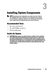
Recommended Tools • Key to servicing that came with hot-swappable hard drives and an LCD panel. Installing System Components 79 The illustrations in your system may only be ..., your product documentation, or as authorized in this section show a system with the product. Read and follow the safety instructions that is not authorized by Dell is not covered by the online or telephone service and support team. Damage due to the system keylock • #1 and #2 Phillips screwdrivers • Wrist grounding...
Recommended Tools • Key to servicing that came with hot-swappable hard drives and an LCD panel. Installing System Components 79 The illustrations in your system may only be ..., your product documentation, or as authorized in this section show a system with the product. Read and follow the safety instructions that is not authorized by Dell is not covered by the online or telephone service and support team. Damage due to the system keylock • #1 and #2 Phillips screwdrivers • Wrist grounding...
Hardware Owner's Manual
Page 81
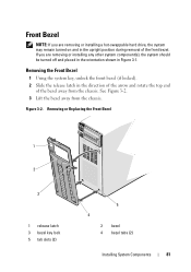
...component(s), the system should be turned off and placed in the orientation shown in Figure 3-1. Removing or Replacing the Front Bezel 1 2 3 1 release latch 3 bezel key lock 5 tab slots (2) 5 4 2 bezel 4 bezel tabs (2) Installing System Components 81 Figure 3-2. Front Bezel NOTE: If you are removing or installing a hot-...the bezel away from the chassis. See Figure 3-2. 3 Lift the bezel away from the chassis. Removing the Front Bezel 1 Using the system key, unlock the front bezel (if locked). 2 Slide the release latch in the direction of the arrow and rotate the top end of the ...
...component(s), the system should be turned off and placed in the orientation shown in Figure 3-1. Removing or Replacing the Front Bezel 1 2 3 1 release latch 3 bezel key lock 5 tab slots (2) 5 4 2 bezel 4 bezel tabs (2) Installing System Components 81 Figure 3-2. Front Bezel NOTE: If you are removing or installing a hot-...the bezel away from the chassis. See Figure 3-2. 3 Lift the bezel away from the chassis. Removing the Front Bezel 1 Using the system key, unlock the front bezel (if locked). 2 Slide the release latch in the direction of the arrow and rotate the top end of the ...
Hardware Owner's Manual
Page 82
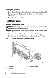
Figure 3-3. Installing the Front Bezel 1 Insert the bezel tabs into place. 3 Using the system key, lock the bezel. Front Bezel Inserts Removing the Front Bezel Insert NOTE: Before installing a drive in the chassis. You can attach the screws to new ...
Figure 3-3. Installing the Front Bezel 1 Insert the bezel tabs into place. 3 Using the system key, lock the bezel. Front Bezel Inserts Removing the Front Bezel Insert NOTE: Before installing a drive in the chassis. You can attach the screws to new ...

Hardware Owner's Manual
Page 112
... Align the memory module's edge connector with your thumbs to lock the memory module into the socket. NOTE: The memory module socket has an alignment key that have memory modules installed. 12 Repeat step 8 through step 11 of the memory module socket, and insert the memory module in the socket. ...the other sockets that allows you to install the remaining memory modules. See "Installing the Expansion Card Stabilizer" on the memory module with the alignment key of this procedure to install the memory module in the socket in only one way. 11 Press down on page 87. 15 Close the system....
... Align the memory module's edge connector with your thumbs to lock the memory module into the socket. NOTE: The memory module socket has an alignment key that have memory modules installed. 12 Repeat step 8 through step 11 of the memory module socket, and insert the memory module in the socket. ...the other sockets that allows you to install the remaining memory modules. See "Installing the Expansion Card Stabilizer" on the memory module with the alignment key of this procedure to install the memory module in the socket in only one way. 11 Press down on page 87. 15 Close the system....

Hardware Owner's Manual
Page 124
...and then specify the USB memory key in the boot sequence in your product documentation, or as directed by the Internal USB Port option in the Integrated Devices screen of the SD card into the slot. Damage due to servicing that is not authorized by Dell is not covered by a certified...of the media slot. 2 With the label side facing up, insert the contact-pin end of the System Setup program. Internal USB Memory Keys The USB memory key installed inside your warranty. See Figure 6-1. 124 Installing System Components Removing a VFlash Media To remove the VFlash media, push inward on the ...
...and then specify the USB memory key in the boot sequence in your product documentation, or as directed by the Internal USB Port option in the Integrated Devices screen of the SD card into the slot. Damage due to servicing that is not authorized by Dell is not covered by a certified...of the media slot. 2 With the label side facing up, insert the contact-pin end of the System Setup program. Internal USB Memory Keys The USB memory key installed inside your warranty. See Figure 6-1. 124 Installing System Components Removing a VFlash Media To remove the VFlash media, push inward on the ...

Hardware Owner's Manual
Page 125
See "Closing the System" on page 86. 6 Place the system upright on a flat surface. 7 Reattach any peripherals and connect the system to an electrical outlet. 8 Turn on page 58. Figure 3-21. See Figure 3-21. 5 Close the system. 4 Insert the USB memory key into the USB connector. See "Entering the System Setup Program" on the system and attached peripherals. 9 Enter the System Setup program and verify that the USB key has been detected by the system. Removing or Installing a USB Memory Key 1 2 1 USB memory key 2 USB memory key connector Installing System Components 125
See "Closing the System" on page 86. 6 Place the system upright on a flat surface. 7 Reattach any peripherals and connect the system to an electrical outlet. 8 Turn on page 58. Figure 3-21. See Figure 3-21. 5 Close the system. 4 Insert the USB memory key into the USB connector. See "Entering the System Setup Program" on the system and attached peripherals. 9 Enter the System Setup program and verify that the USB key has been detected by the system. Removing or Installing a USB Memory Key 1 2 1 USB memory key 2 USB memory key connector Installing System Components 125

Hardware Owner's Manual
Page 128
Figure 3-23. Removing a Processor 1 6 2 3 4 5 1 processor 3 processor shield 5 socket key (2) 2 notch in processor (2) 4 ZIF socket 6 socket-release lever CAUTION: Be careful not to bend any of the pins on the ZIF socket when removing the processor. Bending the pins can permanently damage the system board. 128 Installing System Components
Figure 3-23. Removing a Processor 1 6 2 3 4 5 1 processor 3 processor shield 5 socket key (2) 2 notch in processor (2) 4 ZIF socket 6 socket-release lever CAUTION: Be careful not to bend any of the pins on the ZIF socket when removing the processor. Bending the pins can permanently damage the system board. 128 Installing System Components


