
Information Update
Page 3
...without notice. © 2007-2008 Dell Inc. All rights reserved. Dell Inc. Physical Height Width Depth Weight (maximum configuration) 41.3 cm (16.25 inches) 18.7 cm (7.36 inches) 45.8 cm (18 inches) 13 kg (28.6 lb) Information in this text: Dell, the DELL logo, and PowerEdge are trademarks of Novell, Inc., in... or updated. • A DVD-RW drive has been added to the list of supported optical drives. • The amount of graphics memory for the ATI ES 1000 2D graphics controller is 32 MB instead of supported optical drives. SUSE is strictly forbidden. Other trademarks and trade...
...without notice. © 2007-2008 Dell Inc. All rights reserved. Dell Inc. Physical Height Width Depth Weight (maximum configuration) 41.3 cm (16.25 inches) 18.7 cm (7.36 inches) 45.8 cm (18 inches) 13 kg (28.6 lb) Information in this text: Dell, the DELL logo, and PowerEdge are trademarks of Novell, Inc., in... or updated. • A DVD-RW drive has been added to the list of supported optical drives. • The amount of graphics memory for the ATI ES 1000 2D graphics controller is 32 MB instead of supported optical drives. SUSE is strictly forbidden. Other trademarks and trade...
Getting Started Guide
Page 5
single or dual rank. • Support for the following internal hard-drive (non-hot-plug) configurations: - Up to two internal 3.5-inch Serial-Attached SCSI (SAS) hard drives with an optional SAS RAID controller card: simple, spanned, striped (RAID 0), and mirrored (RAID ... maximum of 667- See the Hardware Owner's Manual. • A minimum of 512 MB of 8 GB DDR II SDRAM memory by installing 512-MB, 1-GB, or 2-GB unbuffered ECC memory modules in the four memory module sockets on the system board; System Features This section describes the major hardware and software features of your...
single or dual rank. • Support for the following internal hard-drive (non-hot-plug) configurations: - Up to two internal 3.5-inch Serial-Attached SCSI (SAS) hard drives with an optional SAS RAID controller card: simple, spanned, striped (RAID 0), and mirrored (RAID ... maximum of 667- See the Hardware Owner's Manual. • A minimum of 512 MB of 8 GB DDR II SDRAM memory by installing 512-MB, 1-GB, or 2-GB unbuffered ECC memory modules in the four memory module sockets on the system board; System Features This section describes the major hardware and software features of your...
Getting Started Guide
Page 12
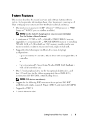
Video Video type Video memory Power AC power supply (per power supply) Wattage Voltage Heat dissipation CMOS Backup Battery Physical Height Width Depth Weight (maximum configuration) Integrated 32 MB 305 W 100-120V/200-240V, 9/4.5A, 50/60 Hz, 1040 BTU/Hour CR 2032 3.0-V lithium ion coin cell 391.55 mm (15.42 inches) 186.9 mm (7.40 inches) 418.5 mm (16.50 inches) 13 kg (28.70 lb) 10 Getting Started With Your System
Video Video type Video memory Power AC power supply (per power supply) Wattage Voltage Heat dissipation CMOS Backup Battery Physical Height Width Depth Weight (maximum configuration) Integrated 32 MB 305 W 100-120V/200-240V, 9/4.5A, 50/60 Hz, 1040 BTU/Hour CR 2032 3.0-V lithium ion coin cell 391.55 mm (15.42 inches) 186.9 mm (7.40 inches) 418.5 mm (16.50 inches) 13 kg (28.70 lb) 10 Getting Started With Your System

Hardware Owner's Manual (PDF)
Page 4
System Setup Options 33 Main Screen 33 Memory Information Screen 35 CPU Information Screen 36 SATA Configuration Screen 36 Integrated Devices Screen 37 System Security Screen 38 Exit Screen 39 System and Setup Password Features 39 Using the System Password 40 Using ...
System Setup Options 33 Main Screen 33 Memory Information Screen 35 CPU Information Screen 36 SATA Configuration Screen 36 Integrated Devices Screen 37 System Security Screen 38 Exit Screen 39 System and Setup Password Features 39 Using the System Password 40 Using ...
Hardware Owner's Manual (PDF)
Page 5
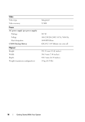
... Expansion Card 70 Installing an Expansion Card 72 SAS Controller Expansion Card 73 Memory 75 Memory Module Upgrade Kits 75 Memory Module Installation Guidelines 75 Addressing Memory With 8-GB Configurations (Microsoft® Windows® Operating System Only 76 Removing a Memory Module 77 Installing a Memory Module 77 Microprocessor 79 Removing the Processor 79 Replacing the Processor 82 Cooling...
... Expansion Card 70 Installing an Expansion Card 72 SAS Controller Expansion Card 73 Memory 75 Memory Module Upgrade Kits 75 Memory Module Installation Guidelines 75 Addressing Memory With 8-GB Configurations (Microsoft® Windows® Operating System Only 76 Removing a Memory Module 77 Installing a Memory Module 77 Microprocessor 79 Removing the Processor 79 Replacing the Processor 82 Cooling...
Hardware Owner's Manual (PDF)
Page 19
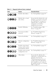
Possible USB failure. See "Getting Help" on page 137. configuration error. Corrective Action See "Getting Help" on page 137. No memory modules detected. See "Getting Help" on page 103 for information on page 114. See "Troubleshooting Your System" on page 137. If the ... "Hard Drives" on page 64 or "Diskette Drive" on page 52 for the appropriate drive installed in your system. See "Troubleshooting System Memory" on the drives installed in your system. Memory configuration See "Troubleshooting System error. Diskette drive or hard drive failure. Table 1-5.
Possible USB failure. See "Getting Help" on page 137. configuration error. Corrective Action See "Getting Help" on page 137. No memory modules detected. See "Getting Help" on page 103 for information on page 114. See "Troubleshooting Your System" on page 137. If the ... "Hard Drives" on page 64 or "Diskette Drive" on page 52 for the appropriate drive installed in your system. See "Troubleshooting System Memory" on the drives installed in your system. Memory configuration See "Troubleshooting System error. Diskette drive or hard drive failure. Table 1-5.

Hardware Owner's Manual (PDF)
Page 26
...or the requested sector is defective. System Messages (continued) Message Operating system not found PCI BIOS failed to install Plug and play configuration error Read fault Requested sector not found Causes Corrective Actions See "Troubleshooting a Hard Drive" on page 120. 26 About Your ... on page 120. If the problem persists, see "Getting Help" on the disk, or the requested sector is See "Troubleshooting improperly configured. If the problem persists, see "Getting Help" on page 114." BIOS checksum failure Ensure that all network detected. cards and connections are...
...or the requested sector is defective. System Messages (continued) Message Operating system not found PCI BIOS failed to install Plug and play configuration error Read fault Requested sector not found Causes Corrective Actions See "Troubleshooting a Hard Drive" on page 120. 26 About Your ... on page 120. If the problem persists, see "Getting Help" on the disk, or the requested sector is See "Troubleshooting improperly configured. If the problem persists, see "Getting Help" on page 114." BIOS checksum failure Ensure that all network detected. cards and connections are...
Hardware Owner's Manual (PDF)
Page 29
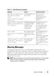
... prompts you that accompanied the operating system or application. For example, before the system continues a task. About Your System 29 Warning: The installed memory configuration is unsupported. A DIMM configuration Reinstall the memory is not optimal. modules are generated by typing y (yes) or n (no). NOTE: Warning messages are not See "Troubleshooting matched pairs. A fatal error...
... prompts you that accompanied the operating system or application. For example, before the system continues a task. About Your System 29 Warning: The installed memory configuration is unsupported. A DIMM configuration Reinstall the memory is not optimal. modules are generated by typing y (yes) or n (no). NOTE: Warning messages are not See "Troubleshooting matched pairs. A fatal error...

Hardware Owner's Manual (PDF)
Page 31
...31 If an error message appears while the system is normal for your system to familiarize yourself with your system configuration and optional settings. NOTE: After installing a memory upgrade, it is booting, make a note of the message and suggestions for future reference. NOTE: To ensure ...options-for example, the time or date • Enable or disable integrated devices • Correct discrepancies between the installed hardware and configuration settings Entering the System Setup Program 1 Turn on page 20 for an explanation of the message. Before entering the System Setup program,...
...31 If an error message appears while the system is normal for your system to familiarize yourself with your system configuration and optional settings. NOTE: After installing a memory upgrade, it is booting, make a note of the message and suggestions for future reference. NOTE: To ensure ...options-for example, the time or date • Enable or disable integrated devices • Correct discrepancies between the installed hardware and configuration settings Entering the System Setup Program 1 Turn on page 20 for an explanation of the message. Before entering the System Setup program,...

Hardware Owner's Manual (PDF)
Page 34
... A V next to change based on the main System Setup program screen. keys to the device indicates that appear on the system configuration. CPU Information Displays information for security devices. See "Integrated Devices Screen" on page 38. 34 Using the System Setup Program System Security...and descriptions for each group of the devices. NOTE: The options for the system to disable or enable the device. Memory Information See "Memory Information Screen" on page 36. The default boot sequence is enabled. NOTE: At least one of information fields that ...
... A V next to change based on the main System Setup program screen. keys to the device indicates that appear on the system configuration. CPU Information Displays information for security devices. See "Integrated Devices Screen" on page 38. 34 Using the System Setup Program System Security...and descriptions for each group of the devices. NOTE: The options for the system to disable or enable the device. Memory Information See "Memory Information Screen" on page 36. The default boot sequence is enabled. NOTE: At least one of information fields that ...

Hardware Owner's Manual (PDF)
Page 36
... in the processor. Displays the clock speed of each processor. Displays the amount of cores in the system, the SATA Configuration screen changes. CPU Information Screen Table 2-4 lists the options and descriptions for the processor. Displays the family and model number...not have user-selectable settings. Displays the number of cache memory for the information fields that appear on the CPU Information screen. Table 2-4. This option does not have user-selectable settings. SATA Configuration Screen Table 2-5 lists the options and descriptions for the ...
... in the processor. Displays the clock speed of each processor. Displays the amount of cores in the system, the SATA Configuration screen changes. CPU Information Screen Table 2-4 lists the options and descriptions for the processor. Displays the family and model number...not have user-selectable settings. Displays the number of cache memory for the information fields that appear on the CPU Information screen. Table 2-4. This option does not have user-selectable settings. SATA Configuration Screen Table 2-5 lists the options and descriptions for the ...

Hardware Owner's Manual (PDF)
Page 75
... 75 Table 3-2 illustrates memory configuration guidelines. NOTICE: If you remove your original memory modules from the system during a memory upgrade, keep them separate from any new memory modules that you may have, even if you purchased the new memory modules from Dell. Memory Module Installation Guidelines • If only one memory module is installed, the memory will significantly reduce system...
... 75 Table 3-2 illustrates memory configuration guidelines. NOTICE: If you remove your original memory modules from the system during a memory upgrade, keep them separate from any new memory modules that you may have, even if you purchased the new memory modules from Dell. Memory Module Installation Guidelines • If only one memory module is installed, the memory will significantly reduce system...
Hardware Owner's Manual (PDF)
Page 76
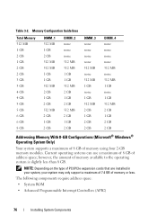
.... Table 3-2. The following components require address space: • System ROM • Advanced Programmable Interrupt Controllers (APIC) 76 Installing System Components Memory Configuration Guidelines Total Memory 512 MB 1 GB 2 GB 1 GB 2 GB 2 GB 3 GB 3 GB 4 GB 4 GB 5 GB 5 GB 6 GB 6 GB 8 GB DIMM_1 512 MB 1 GB 2 GB 512 MB 512... 1 GB 2 GB 2 GB DIMM_4 none none none none 512 MB none 512 MB 1 GB none 1 GB 512 MB 2 GB 1 GB 2 GB 2 GB Addressing Memory With 8-GB Configurations (Microsoft® Windows® Operating System Only) Your system supports a maximum of 8 GB of address space;
.... Table 3-2. The following components require address space: • System ROM • Advanced Programmable Interrupt Controllers (APIC) 76 Installing System Components Memory Configuration Guidelines Total Memory 512 MB 1 GB 2 GB 1 GB 2 GB 2 GB 3 GB 3 GB 4 GB 4 GB 5 GB 5 GB 6 GB 6 GB 8 GB DIMM_1 512 MB 1 GB 2 GB 512 MB 512... 1 GB 2 GB 2 GB DIMM_4 none none none none 512 MB none 512 MB 1 GB none 1 GB 512 MB 2 GB 1 GB 2 GB 2 GB Addressing Memory With 8-GB Configurations (Microsoft® Windows® Operating System Only) Your system supports a maximum of 8 GB of address space;

Hardware Owner's Manual (PDF)
Page 79
... is correct, press to exit the System Setup program. 14 Run the system diagnostics to verify that the new memory does not match the existing configuration information and generates the following message: The amount of future options in a 939-pin micro pin grid array (PGA) package. ...The processor and its associated internal cache memory are contained in speed and functionality. See "System Setup Options" on page 128. ...
... is correct, press to exit the System Setup program. 14 Run the system diagnostics to verify that the new memory does not match the existing configuration information and generates the following message: The amount of future options in a 939-pin micro pin grid array (PGA) package. ...The processor and its associated internal cache memory are contained in speed and functionality. See "System Setup Options" on page 128. ...

Hardware Owner's Manual (PDF)
Page 102
...SATA connector(s) • Intrusion switch cable from which they were removed. See "Installing an Expansion Card" on page 72. 7 Depending on your configuration, connect the following cables that you removed in the same sockets from the INTRUSION connector 8 Close the system. See Figure 6-2. • Two... hard-drive data cable(s) to the electrical outlet, and turn on the system. 102 Installing System Components 5 Install the memory modules in "Removing the System Board" on page 100. See "Installing a Memory Module" on page 77. 6 Install the expansion cards and connect any cables.
...SATA connector(s) • Intrusion switch cable from which they were removed. See "Installing an Expansion Card" on page 72. 7 Depending on your configuration, connect the following cables that you removed in the same sockets from the INTRUSION connector 8 Close the system. See Figure 6-2. • Two... hard-drive data cable(s) to the electrical outlet, and turn on the system. 102 Installing System Components 5 Install the memory modules in "Removing the System Board" on page 100. See "Installing a Memory Module" on page 77. 6 Install the expansion cards and connect any cables.

Hardware Owner's Manual (PDF)
Page 104
..., such as a printer, keyboard, mouse, or other peripherals (such as the monitor, keyboard, or mouse. In this system configuration, the monitor cable should normally be connected to the connector on page 104. Before you access a drive. Troubleshooting the Video Subsystem... Problem • Monitor is not working properly. • Video memory is faulty. Checking the Equipment This section provides troubleshooting procedures for the system, monitor, and other external device). Action 1 Check...
..., such as a printer, keyboard, mouse, or other peripherals (such as the monitor, keyboard, or mouse. In this system configuration, the monitor cable should normally be connected to the connector on page 104. Before you access a drive. Troubleshooting the Video Subsystem... Problem • Monitor is not working properly. • Video memory is faulty. Checking the Equipment This section provides troubleshooting procedures for the system, monitor, and other external device). Action 1 Check...
Hardware Owner's Manual (PDF)
Page 116
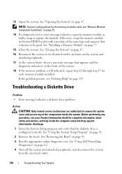
... system. 18 If the memory problem is still indicated, repeat step 12 through step 17 for the memory modules exist; See "Opening the System" on page 31. 2 Remove the bezel. NOTE: Several configurations for each memory module installed. Otherwise, swap the memory module in the first DIMM...peripherals, and disconnect the system from the electrical outlet. 116 Troubleshooting Your System See "Using Dell PowerEdge Diagnostics" on page 95. 3 Run the appropriate online diagnostic test. See "Installing a Memory Module" on page 137. 13 Open the system. See "Closing the System" on page ...
... system. 18 If the memory problem is still indicated, repeat step 12 through step 17 for the memory modules exist; See "Opening the System" on page 31. 2 Remove the bezel. NOTE: Several configurations for each memory module installed. Otherwise, swap the memory module in the first DIMM...peripherals, and disconnect the system from the electrical outlet. 116 Troubleshooting Your System See "Using Dell PowerEdge Diagnostics" on page 95. 3 Run the appropriate online diagnostic test. See "Installing a Memory Module" on page 137. 13 Open the system. See "Closing the System" on page ...
Hardware Owner's Manual (PDF)
Page 173
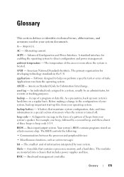
...copy of the area or room where the system is turned off. blade - A battery that maintains system configuration, date, and time information in the form of a pattern of memory when the system is located. BMC - application - backup battery - Basic input/output system. A module... that includes power supplies and fans. Ampere(s). An individual code assigned to direct configuration and power management. beep code - A ...
...copy of the area or room where the system is turned off. blade - A battery that maintains system configuration, date, and time information in the form of a pattern of memory when the system is located. BMC - application - backup battery - Basic input/output system. A module... that includes power supplies and fans. Ampere(s). An individual code assigned to direct configuration and power management. beep code - A ...
Hardware Owner's Manual (PDF)
Page 175
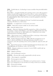
... when you to a client system. A method of DRAM chips. A comprehensive set of translating Internet domain names, such as www.dell.com, into IP addresses, such as network drivers- directory - Domain Name System. ECC - Error checking and correction. EMC - ... program for your system. A program that branch off them. Dynamic Host Configuration Protocol. diagnostics - Each disk has a "root" directory. ESD - DIMM - DIN - Desktop Management Interface. DNS - Dynamic random-access memory. A system's RAM is usually made up entirely of automatically assigning an IP...
... when you to a client system. A method of DRAM chips. A comprehensive set of translating Internet domain names, such as www.dell.com, into IP addresses, such as network drivers- directory - Domain Name System. ECC - Error checking and correction. EMC - ... program for your system. A program that branch off them. Dynamic Host Configuration Protocol. diagnostics - Each disk has a "root" directory. ESD - DIMM - DIN - Desktop Management Interface. DNS - Dynamic random-access memory. A system's RAM is usually made up entirely of automatically assigning an IP...

Hardware Owner's Manual (PDF)
Page 179
... which a set of physical drives stores data and one of memory, such as a diskette drive or keyboard, connected to signal the processor about hardware errors. A system can contain several different forms of the concepts used for maintaining the date, time, and system configuration information. mm - Nanosecond(s). NTFS - Each partition can divide a hard...
... which a set of physical drives stores data and one of memory, such as a diskette drive or keyboard, connected to signal the processor about hardware errors. A system can contain several different forms of the concepts used for maintaining the date, time, and system configuration information. mm - Nanosecond(s). NTFS - Each partition can divide a hard...


