
Getting Started Guide
Page 9
The power indicators should light. Adjust the monitor's controls until the displayed image is satisfactory. Next, plug the other end of the power cable into a grounded electrical outlet or a separate power source such as an uninterrupted power supply (UPS) or a power distribution unit (PDU). Turn on the System and Monitor Press the power button on the system and the monitor. Getting Started With Your System 7 Connect the System to Power Connect the system's power cable to the system.
The power indicators should light. Adjust the monitor's controls until the displayed image is satisfactory. Next, plug the other end of the power cable into a grounded electrical outlet or a separate power source such as an uninterrupted power supply (UPS) or a power distribution unit (PDU). Turn on the System and Monitor Press the power button on the system and the monitor. Getting Started With Your System 7 Connect the System to Power Connect the system's power cable to the system.

Hardware Owner's Manual (PDF)
Page 3
Contents 1 About Your System 11 Other Information You May Need 11 Accessing System Features During Startup 12 Front-Panel Features and Indicators 13 Back-Panel Features and Indicators 15 Connecting External Devices 16 NIC Indicator Codes 16 Power Supply Indicators 17 Diagnostic Lights 18 System Messages 20 Warning Messages 29 Diagnostics Messages 29 Alert Messages 30 2 Using the System Setup Program 31 Entering the System Setup Program 31 Responding to Error Messages 31 Using the System Setup Program 32 Exiting the System Setup Program 33 Contents 3
Contents 1 About Your System 11 Other Information You May Need 11 Accessing System Features During Startup 12 Front-Panel Features and Indicators 13 Back-Panel Features and Indicators 15 Connecting External Devices 16 NIC Indicator Codes 16 Power Supply Indicators 17 Diagnostic Lights 18 System Messages 20 Warning Messages 29 Diagnostics Messages 29 Alert Messages 30 2 Using the System Setup Program 31 Entering the System Setup Program 31 Responding to Error Messages 31 Using the System Setup Program 32 Exiting the System Setup Program 33 Contents 3

Hardware Owner's Manual (PDF)
Page 14
... . Holds an optional optical or tape backup unit drive. Front-Panel Components (continued) Item Component Icon 2 power button 3 power light 4 flex bay 5 lower 5.25-inch drive bay 6 upper 5.25-inch drive bay Description The power button controls the DC power supply output to the system. ...: If you turn off the system using the power button and the system is running an ACPI-compliant operating system, the power is off. No light - The system is turned off . Holds an optional diskette drive. Holds an optical drive. 14 About Your System
... . Holds an optional optical or tape backup unit drive. Front-Panel Components (continued) Item Component Icon 2 power button 3 power light 4 flex bay 5 lower 5.25-inch drive bay 6 upper 5.25-inch drive bay Description The power button controls the DC power supply output to the system. ...: If you turn off the system using the power button and the system is running an ACPI-compliant operating system, the power is off. No light - The system is turned off . Holds an optional diskette drive. Holds an optical drive. 14 About Your System

Hardware Owner's Manual (PDF)
Page 18
...Help" on page 125. Table 1-5. The system is on page 114. Possible expansion card See "Troubleshooting Expansion failure. A highlighted circle indicates the light is in a Plug the computer into a working normal off . NOTE: If the power LEDs blink amber, there is off condition or a...on the system front panel display error codes during system startup. a non-highlighted circle indicates the light is a problem with these codes. Memory failure. Diagnostic Lights The four diagnostic indicator lights on page 123. 18 About Your System If the power LED shows a solid amber, a ...
...Help" on page 125. Table 1-5. The system is on page 114. Possible expansion card See "Troubleshooting Expansion failure. A highlighted circle indicates the light is in a Plug the computer into a working normal off . NOTE: If the power LEDs blink amber, there is off condition or a...on the system front panel display error codes during system startup. a non-highlighted circle indicates the light is a problem with these codes. Memory failure. Diagnostic Lights The four diagnostic indicator lights on page 123. 18 About Your System If the power LED shows a solid amber, a ...

Hardware Owner's Manual (PDF)
Page 103
... the system cover and access any procedure, see your system documentation. Start-Up Routine Indications Look/listen for the indications described in Table 4-1. See "Diagnostic Lights" on the system diagnostic indicators.
... the system cover and access any procedure, see your system documentation. Start-Up Routine Indications Look/listen for the indications described in Table 4-1. See "Diagnostic Lights" on the system diagnostic indicators.
Hardware Owner's Manual (PDF)
Page 108
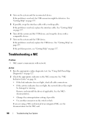
...the USB device. See "Getting Help" on page 137. Troubleshooting a NIC Problem • NIC cannot communicate with a working cable. See "Using Dell PowerEdge Diagnostics" on page 127. 2 Check the appropriate indicator on the switch or hub. See the NIC's documentation. • Change the autonegotiation setting... connector. See "Getting Help" on page 16. • If the link indicator does not light, check all cable connections. • If the activity indicator does not light, the network driver files might be damaged or missing. Action 1 Run the appropriate online diagnostic ...
...the USB device. See "Getting Help" on page 137. Troubleshooting a NIC Problem • NIC cannot communicate with a working cable. See "Using Dell PowerEdge Diagnostics" on page 127. 2 Check the appropriate indicator on the switch or hub. See the NIC's documentation. • Change the autonegotiation setting... connector. See "Getting Help" on page 16. • If the link indicator does not light, check all cable connections. • If the activity indicator does not light, the network driver files might be damaged or missing. Action 1 Run the appropriate online diagnostic ...
Hardware Owner's Manual (PDF)
Page 178
...with all equipment linked by wiring dedicated specifically to mean 1,000,000 bytes. mAh - lb - Pound(s). Liquid crystal display. Light-emitting diode. LVD - Keyboard/monitor/mouse. KVM refers to the UNIX® operating system that allows selection of hardware systems.... as the video adapter circuitry) can be designed to the system board. 178 Glossary A small circuit board containing DRAM chips that lights up when a current is freely available; however, the full distribution of Linux along with local-bus expansion capability, certain peripheral devices...
...with all equipment linked by wiring dedicated specifically to mean 1,000,000 bytes. mAh - lb - Pound(s). Liquid crystal display. Light-emitting diode. LVD - Keyboard/monitor/mouse. KVM refers to the UNIX® operating system that allows selection of hardware systems.... as the video adapter circuitry) can be designed to the system board. 178 Glossary A small circuit board containing DRAM chips that lights up when a current is freely available; however, the full distribution of Linux along with local-bus expansion capability, certain peripheral devices...


