
Hardware Owner's Manual (PDF)
Page 3
Contents 1 About Your System 11 Other Information You May Need 11 Accessing System Features During Startup 12 Front-Panel Features and Indicators 13 Back-Panel Features and Indicators 15 Connecting External Devices 16 NIC Indicator Codes 16 Power Supply Indicators 17 Diagnostic Lights 18 System Messages 20 Warning Messages 29 Diagnostics Messages 29 Alert Messages 30 2 Using the System Setup Program 31 Entering the System Setup Program 31 Responding to Error Messages 31 Using the System Setup Program 32 Exiting the System Setup Program 33 Contents 3
Contents 1 About Your System 11 Other Information You May Need 11 Accessing System Features During Startup 12 Front-Panel Features and Indicators 13 Back-Panel Features and Indicators 15 Connecting External Devices 16 NIC Indicator Codes 16 Power Supply Indicators 17 Diagnostic Lights 18 System Messages 20 Warning Messages 29 Diagnostics Messages 29 Alert Messages 30 2 Using the System Setup Program 31 Entering the System Setup Program 31 Responding to Error Messages 31 Using the System Setup Program 32 Exiting the System Setup Program 33 Contents 3

Hardware Owner's Manual (PDF)
Page 14
...ACPI-compliant operating system, the system performs a graceful shutdown before Power-On Self Test (POST). See "Diagnostic Lights" on . Holds an optical drive. 14 About Your System No light - Blinking amber - Steady amber - Steady green - There is pressed. The system is turned off...ACPI-compliant operating system, the power is turned off . Table 1-2. Front-Panel Components (continued) Item Component Icon 2 power button 3 power light 4 flex bay 5 lower 5.25-inch drive bay 6 upper 5.25-inch drive bay Description The power button controls the DC power supply...
...ACPI-compliant operating system, the system performs a graceful shutdown before Power-On Self Test (POST). See "Diagnostic Lights" on . Holds an optical drive. 14 About Your System No light - Blinking amber - Steady amber - Steady green - There is pressed. The system is turned off...ACPI-compliant operating system, the power is turned off . Table 1-2. Front-Panel Components (continued) Item Component Icon 2 power button 3 power light 4 flex bay 5 lower 5.25-inch drive bay 6 upper 5.25-inch drive bay Description The power button controls the DC power supply...

Hardware Owner's Manual (PDF)
Page 18
...failure power button. Table 1-5 lists the causes and possible corrective actions associated with the power supply. Table 1-5. The diagnostic lights are not lit after POST. See "Troubleshooting the Microprocessor" on the system front panel display error codes during system ...before Power-On Self Test (POST). Possible processor failure. Diagnostic Lights The four diagnostic indicator lights on page 125. a non-highlighted circle indicates the light is in a Plug the computer into a working normal off . Diagnostic Indicator Codes Code Causes Corrective Action The computer is on ...
...failure power button. Table 1-5 lists the causes and possible corrective actions associated with the power supply. Table 1-5. The diagnostic lights are not lit after POST. See "Troubleshooting the Microprocessor" on the system front panel display error codes during system ...before Power-On Self Test (POST). Possible processor failure. Diagnostic Lights The four diagnostic indicator lights on page 125. a non-highlighted circle indicates the light is in a Plug the computer into a working normal off . Diagnostic Indicator Codes Code Causes Corrective Action The computer is on ...

Hardware Owner's Manual (PDF)
Page 103
...: Only trained service technicians are authorized to service the system except as explained in Table 4-1. See "Diagnostic Lights" on page 116. The monitor's power indicator. The keyboard indicators. See "Troubleshooting an Optical Drive" on the system diagnostic indicators. While working inside the system. Table 4-1. Start-Up Routine Indications Look/listen for: Action A code...
...: Only trained service technicians are authorized to service the system except as explained in Table 4-1. See "Diagnostic Lights" on page 116. The monitor's power indicator. The keyboard indicators. See "Troubleshooting an Optical Drive" on the system diagnostic indicators. While working inside the system. Table 4-1. Start-Up Routine Indications Look/listen for: Action A code...
Hardware Owner's Manual (PDF)
Page 108
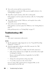
... the autonegotiation setting, if possible. • Use another connector on page 16. • If the link indicator does not light, check all cable connections. • If the activity indicator does not light, the network driver files might be damaged or missing. 4 Turn on page 137. If the problem persists, see the documentation... system and the reconnected device. If the problem is resolved, the USB connector might be defective. See "Getting Help" on the NIC connector. See "Using Dell PowerEdge Diagnostics" on page 127. 2 Check the appropriate indicator on page 137.
... the autonegotiation setting, if possible. • Use another connector on page 16. • If the link indicator does not light, check all cable connections. • If the activity indicator does not light, the network driver files might be damaged or missing. 4 Turn on page 137. If the problem persists, see the documentation... system and the reconnected device. If the problem is resolved, the USB connector might be defective. See "Getting Help" on the NIC connector. See "Using Dell PowerEdge Diagnostics" on page 127. 2 Check the appropriate indicator on page 137.


