Information Update
Page 1
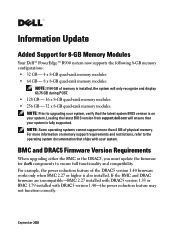
... Firmware Version Requirements When upgrading either the BMC or the DRAC5, you must update the firmware for 8-GB Memory Modules Your Dell™ PowerEdge™ R900 system now supports the following 8-GB memory configurations: • 32 GB - 4 x 8-GB quad-rank memory modules • 64 GB - 8 x 8-GB quad-rank ...-BMC 2.27 installed with DRAC5 version 1.33 or BMC 1.79 installed with your system is also installed. Loading the latest BIOS version from support.dell.com will only recognize and display 63.75 GB during POST. • 128 GB - 16 x 8-GB quad-rank memory modules • 256...
... Firmware Version Requirements When upgrading either the BMC or the DRAC5, you must update the firmware for 8-GB Memory Modules Your Dell™ PowerEdge™ R900 system now supports the following 8-GB memory configurations: • 32 GB - 4 x 8-GB quad-rank memory modules • 64 GB - 8 x 8-GB quad-rank ...-BMC 2.27 installed with DRAC5 version 1.33 or BMC 1.79 installed with your system is also installed. Loading the latest BIOS version from support.dell.com will only recognize and display 63.75 GB during POST. • 128 GB - 16 x 8-GB quad-rank memory modules • 256...
Getting Started Guide
Page 5
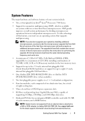
...174; Processors 7300 Series. • Support for the latest support information about booting from Dell. See support.dell.com for symmetric multiprocessing (SMP), which is not supported from Dell contains the correct version of the microprocessor as well as additional microprocessors. Not all versions ... greatly improves overall system performance by installing combinations of 512-MB, 1-GB, 2-GB, or 4-GB memory modules in a 1 + 1 redundant configuration. • Four fan modules, each comprised of two dual-rotor fans, for a total of eight cooling fans. • Three x4 and four...
...174; Processors 7300 Series. • Support for the latest support information about booting from Dell. See support.dell.com for symmetric multiprocessing (SMP), which is not supported from Dell contains the correct version of the microprocessor as well as additional microprocessors. Not all versions ... greatly improves overall system performance by installing combinations of 512-MB, 1-GB, 2-GB, or 4-GB memory modules in a 1 + 1 redundant configuration. • Four fan modules, each comprised of two dual-rotor fans, for a total of eight cooling fans. • Three x4 and four...

Getting Started Guide
Page 7
... included with your system provide documentation and tools for more information. This service may be offered in this document or as expected, see www.dell.com/training for configuring and managing your system. • Updates are sometimes included with your rack solution describes how to install your Hardware Owner's Manual. see your...
... included with your system provide documentation and tools for more information. This service may be offered in this document or as expected, see www.dell.com/training for configuring and managing your system. • Updates are sometimes included with your rack solution describes how to install your Hardware Owner's Manual. see your...

Getting Started Guide
Page 8
This section describes the steps to set up your system and identify each item. Keep all shipping materials in your Product Information Guide. Installation and Configuration CAUTION: Before performing the following procedure, read and follow the safety instructions and important regulatory information in case you need them later. 6 Getting Started With Your System Unpacking the System Unpack your system for the first time.
This section describes the steps to set up your system and identify each item. Keep all shipping materials in your Product Information Guide. Installation and Configuration CAUTION: Before performing the following procedure, read and follow the safety instructions and important regulatory information in case you need them later. 6 Getting Started With Your System Unpacking the System Unpack your system for the first time.

Getting Started Guide
Page 15
... mm) 17.6 inches (447 mm) 27.8 inches (706 mm) 90 lbs (40 kg) Environmental NOTE: For additional information about environmental measurements for specific system configurations, see www.dell.com/environmental_datasheets. Temperature Operating 10 to 35°C (50 to 95°F) Storage -40 to 65°C (-40 to 149°F) Relative humidity Operating...
... mm) 17.6 inches (447 mm) 27.8 inches (706 mm) 90 lbs (40 kg) Environmental NOTE: For additional information about environmental measurements for specific system configurations, see www.dell.com/environmental_datasheets. Temperature Operating 10 to 35°C (50 to 95°F) Storage -40 to 65°C (-40 to 149°F) Relative humidity Operating...
Hardware Owner's Manual (PDF)
Page 4
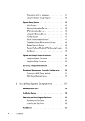
... Screen 49 System and Setup Password Features 49 Using the System Password 50 Using the Setup Password 53 Disabling a Forgotten Password 54 Baseboard Management Controller Configuration . . . 54 Entering the BMC Setup Module 55 BMC Setup Module Options 55 3 Installing System Components 57 Recommended Tools 58 Inside the System 58 Removing and...
... Screen 49 System and Setup Password Features 49 Using the System Password 50 Using the Setup Password 53 Disabling a Forgotten Password 54 Baseboard Management Controller Configuration . . . 54 Entering the BMC Setup Module 55 BMC Setup Module Options 55 3 Installing System Components 57 Recommended Tools 58 Inside the System 58 Removing and...

Hardware Owner's Manual (PDF)
Page 6
Removing a RAID Battery 85 Configuring the Boot Device 86 PCI Express Add-in Cards 86 Installing a PCI Express Card 86 Removing a PCI Express Card 88 Optical Drive 88 Removing the ... Tray 90 Installing an Optical Drive Into an Optical Drive Mounting Tray 92 System Memory 92 General Memory Module Installation Guidelines . 92 Non-Optimal Memory Configurations 93 Memory Sparing Support 93 Memory Mirroring Support 94 Removing a Memory Riser 96 Installing a Memory Riser 98 Memory Population Rules 98 Removing the Memory Riser...
Removing a RAID Battery 85 Configuring the Boot Device 86 PCI Express Add-in Cards 86 Installing a PCI Express Card 86 Removing a PCI Express Card 88 Optical Drive 88 Removing the ... Tray 90 Installing an Optical Drive Into an Optical Drive Mounting Tray 92 System Memory 92 General Memory Module Installation Guidelines . 92 Non-Optimal Memory Configurations 93 Memory Sparing Support 93 Memory Mirroring Support 94 Removing a Memory Riser 96 Installing a Memory Riser 98 Memory Population Rules 98 Removing the Memory Riser...

Hardware Owner's Manual (PDF)
Page 11
... in this document or as a separate document. • The Rack Installation Guide or Rack Installation Instructions included with your system provide documentation and tools for configuring and managing your system's front and back panels provide convenient connectivity and system expansion capability. System conditions can be included within this section. About Your...
... in this document or as a separate document. • The Rack Installation Guide or Rack Installation Instructions included with your system provide documentation and tools for configuring and managing your system's front and back panels provide convenient connectivity and system expansion capability. System conditions can be included within this section. About Your...

Hardware Owner's Manual (PDF)
Page 12
.../or documentation. Keystrokes for more information on setup and use the operating system software. • Documentation for updates on support.dell.com and read the updates first because they often supersede information in other documents. • Release notes or readme files may... features, requirements, installation, and basic operation of the software. • Operating system documentation describes how to install (if necessary), configure, and use of BMC. 12 About Your System Accessing System Features During Startup Table 1-1 describes keystrokes that may be entered during ...
.../or documentation. Keystrokes for more information on setup and use the operating system software. • Documentation for updates on support.dell.com and read the updates first because they often supersede information in other documents. • Release notes or readme files may... features, requirements, installation, and basic operation of the software. • Operating system documentation describes how to install (if necessary), configure, and use of BMC. 12 About Your System Accessing System Features During Startup Table 1-1 describes keystrokes that may be entered during ...
Hardware Owner's Manual (PDF)
Page 13
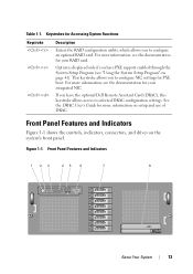
...Program (see the documentation for your integrated NIC. For more information, see the documentation for your RAID card. If you to configure an optional RAID card. Table 1-1. For more information, see "Using the System Setup Program" on page 41). Figure 1-1.... System Functions Keystroke Description Enters the RAID configuration utility, which allows you have the optional Dell Remote Assistant Card (DRAC), this keystroke allows access to selected DRAC configuration settings. Option is displayed only if you to configure NIC settings for more information on the system...
...Program (see the documentation for your integrated NIC. For more information, see the documentation for your RAID card. If you to configure an optional RAID card. Table 1-1. For more information, see "Using the System Setup Program" on page 41). Figure 1-1.... System Functions Keystroke Description Enters the RAID configuration utility, which allows you have the optional Dell Remote Assistant Card (DRAC), this keystroke allows access to selected DRAC configuration settings. Option is displayed only if you to configure NIC settings for more information on the system...

Hardware Owner's Manual (PDF)
Page 18
... documentation for the device specifies otherwise). 18 About Your System After the replacement drive is off . NOTE: For non-RAID configurations, only the drive-activity indicator is selected for removal, the "drive being prepared for operation" pattern appears, followed by the... had a rebuild operation on any reason other than a drive failure. Table 1-2 lists the drive indicator patterns for specific installation and configuration instructions. • Always attach external devices while your system, follow these guidelines: • Most devices must be connected to indicate...
... documentation for the device specifies otherwise). 18 About Your System After the replacement drive is off . NOTE: For non-RAID configurations, only the drive-activity indicator is selected for removal, the "drive being prepared for operation" pattern appears, followed by the... had a rebuild operation on any reason other than a drive failure. Table 1-2 lists the drive indicator patterns for specific installation and configuration instructions. • Always attach external devices while your system, follow these guidelines: • Most devices must be connected to indicate...

Hardware Owner's Manual (PDF)
Page 19
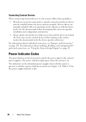
... 41. Back Panel Features and Indicators Figure 1-3 shows the controls, indicators, and connectors located on the system's back panel. For information about enabling, disabling, and configuring I/O ports and connectors, see "Jumpers and Connectors" on page 153. Figure 1-3.
... 41. Back Panel Features and Indicators Figure 1-3 shows the controls, indicators, and connectors located on the system's back panel. For information about enabling, disabling, and configuring I/O ports and connectors, see "Jumpers and Connectors" on page 153. Figure 1-3.
Hardware Owner's Manual (PDF)
Page 20
... controls the power input to a specific connector and device drivers must be installed before turning on the system (unless the documentation for specific installation and configuration instructions. • Always attach external devices while your operating system software or with the device itself.) See the documentation that accompanied the device for the... green when the system is present or whether a power fault has occurred (see "Using the System Setup Program" on . For information about enabling, disabling, and configuring I/O ports and connectors, see Figure 1-4).
... controls the power input to a specific connector and device drivers must be installed before turning on the system (unless the documentation for specific installation and configuration instructions. • Always attach external devices while your operating system software or with the device itself.) See the documentation that accompanied the device for the... green when the system is present or whether a power fault has occurred (see "Using the System Setup Program" on . For information about enabling, disabling, and configuring I/O ports and connectors, see Figure 1-4).

Hardware Owner's Manual (PDF)
Page 22
... system needs attention. Network data is blinking. For information on . off. The NIC is connected to signify when the system is on the SEL and configuring system management settings, see the systems management software documentation. 22 About Your System NIC Indications Each NIC has two indicators that includes a status code followed...
... system needs attention. Network data is blinking. For information on . off. The NIC is connected to signify when the system is on the SEL and configuring system management settings, see the systems management software documentation. 22 About Your System NIC Indications Each NIC has two indicators that includes a status code followed...

Hardware Owner's Manual (PDF)
Page 25
... and reconnected to the type described in the Microprocessor Technical Specifications outlined in an unsupported configuration. Specified processor is missing or bad, and the system is in your configuration unsupported processors match and by Dell. If the problem halted operation. Table 1-5. conform to the AC power source, or... microprocessor is cleared using either Server Assistant or the BMC Management Utility. See "Troubleshooting Processors" on page 147. See the Dell OpenManage Baseboard Management Controller User's Guide for information about these utilities.
... and reconnected to the type described in the Microprocessor Technical Specifications outlined in an unsupported configuration. Specified processor is missing or bad, and the system is in your configuration unsupported processors match and by Dell. If the problem halted operation. Table 1-5. conform to the AC power source, or... microprocessor is cleared using either Server Assistant or the BMC Management Utility. See "Troubleshooting Processors" on page 147. See the Dell OpenManage Baseboard Management Controller User's Guide for information about these utilities.
Hardware Owner's Manual (PDF)
Page 27
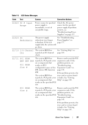
... go down. E1711 PCI PERR The system BIOS has Remove and reseat the PCI B## D## F## reported a PCI parity error expansion cards. resides in PCI "Troubleshooting Slot # configuration space at bus Expansion Cards" on page 165. About Your System 27 If the last page 137. If the problem persists, the The system BIOS...
... go down. E1711 PCI PERR The system BIOS has Remove and reseat the PCI B## D## F## reported a PCI parity error expansion cards. resides in PCI "Troubleshooting Slot # configuration space at bus Expansion Cards" on page 165. About Your System 27 If the last page 137. If the problem persists, the The system BIOS...
Hardware Owner's Manual (PDF)
Page 28
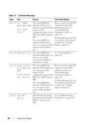
... SERR The system BIOS has Remove and reseat the PCI B## D## F## reported a PCI system expansion cards. resides in PCI "Troubleshooting Slot # configuration space at bus ##, device ##, function ##. If the problem persists, see PCI SERR resides in the specified slot. See "Getting error on a... component that Help" on a component that resides in PCI configuration space at bus Expansion Cards" on a component that there has been an error in the specified slot. The system BIOS has reported ...
... SERR The system BIOS has Remove and reseat the PCI B## D## F## reported a PCI system expansion cards. resides in PCI "Troubleshooting Slot # configuration space at bus ##, device ##, function ##. If the problem persists, see PCI SERR resides in the specified slot. See "Getting error on a... component that Help" on a component that resides in PCI configuration space at bus Expansion Cards" on a component that there has been an error in the specified slot. The system BIOS has reported ...

Hardware Owner's Manual (PDF)
Page 29
.... E1A14 SAS Cable A SAS cable A is missing or bad. See "SAS Controller Card" on subsystem failure. Error detected during memory configuration. Memory System Memory" on page 78. Reseat the cable. See "General Memory Module Installation Guidelines" on page 139. E2011 Mem Config ... page 92. If the problem persists, see your RAID documentation. has been removed from the system. E2012 Unusable Memory Memory is configured, but is installed in the system. LCD Status Messages Code Test Causes Corrective Actions E1811 HDD ## Rbld Abrt The specified hard ...
.... E1A14 SAS Cable A SAS cable A is missing or bad. See "SAS Controller Card" on subsystem failure. Error detected during memory configuration. Memory System Memory" on page 78. Reseat the cable. See "General Memory Module Installation Guidelines" on page 139. E2011 Mem Config ... page 92. If the problem persists, see your RAID documentation. has been removed from the system. E2012 Unusable Memory Memory is configured, but is installed in the system. LCD Status Messages Code Test Causes Corrective Actions E1811 HDD ## Rbld Abrt The specified hard ...

Hardware Owner's Manual (PDF)
Page 31
... Fail General failure after video. E2021 Memory Population Incorrect memory Check screen for specific error messages. Check screen for specific configuration. "Troubleshooting System Memory" on error (SBE) logging, and page 139. Memory error messages. Check screen for specific ...error messages. Check screen for specific error messages. LCD Status Messages Code Test Causes Corrective Actions E201F DRAC Config Dell Remote Assistant Card (DRAC) configuration failure. "##" represents the DIMM implicated by "## & System Memory" on ##" has had a memory page 139....
... Fail General failure after video. E2021 Memory Population Incorrect memory Check screen for specific error messages. Check screen for specific configuration. "Troubleshooting System Memory" on error (SBE) logging, and page 139. Memory error messages. Check screen for specific ...error messages. Check screen for specific error messages. LCD Status Messages Code Test Causes Corrective Actions E201F DRAC Config Dell Remote Assistant Card (DRAC) configuration failure. "##" represents the DIMM implicated by "## & System Memory" on ##" has had a memory page 139....
Hardware Owner's Manual (PDF)
Page 34
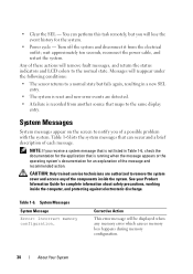
... About Your System Table 1-6 lists the system messages that maps to the normal state. Table 1-6. System Messages System Message Error: Incorrect memory configuration. CAUTION: Only trained service technicians are detected. • A failure is running when the message appears or the operating system's documentation for the application that is ...
... About Your System Table 1-6 lists the system messages that maps to the normal state. Table 1-6. System Messages System Message Error: Incorrect memory configuration. CAUTION: Only trained service technicians are detected. • A failure is running when the message appears or the operating system's documentation for the application that is ...


