Setting Up EMC PowerEdge Server Using Lifecycle Controller
Page 3
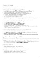
... download the ISO, go to https://www.dell.com/support and type OpenManage DVD in to complete the installation. Installing iDRAC Service Module from iDRAC Express 1. NOTE: After the installation is complete, the Service Module installer file is complete, iDRAC displays the Service Module as "SMINST" on your device list and run the appropriate script: ● On Windows, open the command prompt and run the ISM-Win.bat batch file. ● On Linux, open the...
... download the ISO, go to https://www.dell.com/support and type OpenManage DVD in to complete the installation. Installing iDRAC Service Module from iDRAC Express 1. NOTE: After the installation is complete, the Service Module installer file is complete, iDRAC displays the Service Module as "SMINST" on your device list and run the appropriate script: ● On Windows, open the command prompt and run the ISM-Win.bat batch file. ● On Linux, open the...
EMC PMem 200 Series Users Guide
Page 4
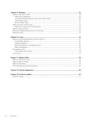
... PMem Disk management...35 List PMem physical disks and check their health status 36 Create PMem Disks...36 Remove PMem disks...37 PMem disk with interleave sets...37 PMem disk creation with interleave sets...37 PMem in memory Mode ...38 Windows troubleshooting and event monitoring...38 Windows Errata...39 Chapter 10: Linux...40 Identify and configure persistent memory device...40 Listing PMem devices...40 Create namespace...40 Mount file system on namespace device...40 Delete namespaces...41 Management utility...41 Check...
... PMem Disk management...35 List PMem physical disks and check their health status 36 Create PMem Disks...36 Remove PMem disks...37 PMem disk with interleave sets...37 PMem disk creation with interleave sets...37 PMem in memory Mode ...38 Windows troubleshooting and event monitoring...38 Windows Errata...39 Chapter 10: Linux...40 Identify and configure persistent memory device...40 Listing PMem devices...40 Create namespace...40 Mount file system on namespace device...40 Delete namespaces...41 Management utility...41 Check...
EMC PMem 200 Series Users Guide
Page 23
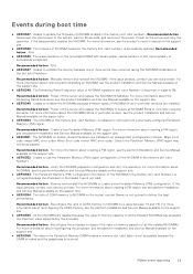
... memory slot . PMem event reporting 23 Recommended Action : N/A ● UEFI0345 : The erase operation on the server and retry the operation. Recommended Action : Power off the server and replace the NVDIMMs to use the Persistent Memory (PM) region configuration of all the installed NVDIMMs. For more information about reconfiguring the processor, see the product Installation and Service Manual available on the support site. ● UEFI0356 : The data in the Persistent Memory DIMM located...
... memory slot . PMem event reporting 23 Recommended Action : N/A ● UEFI0345 : The erase operation on the server and retry the operation. Recommended Action : Power off the server and replace the NVDIMMs to use the Persistent Memory (PM) region configuration of all the installed NVDIMMs. For more information about reconfiguring the processor, see the product Installation and Service Manual available on the support site. ● UEFI0356 : The data in the Persistent Memory DIMM located...
EMC PMem 200 Series Users Guide
Page 24
... reconfiguring the processor, see the Installation and Service Manual of the server available on the support site. ● UEFI0375 : Unable to apply the Persistent Memory (PM) region configuration of the NVDIMM installed in the memory slot . For more information about installation and removal, see the Installation and Service Manual of the PMem Sanitize function. ● UEFI0360 : Unable to complete the Overwrite DIMM operation on the Intel Persistent Memory DIMM with serial number in slot is...
... reconfiguring the processor, see the Installation and Service Manual of the server available on the support site. ● UEFI0375 : Unable to apply the Persistent Memory (PM) region configuration of the NVDIMM installed in the memory slot . For more information about installation and removal, see the Installation and Service Manual of the PMem Sanitize function. ● UEFI0360 : Unable to complete the Overwrite DIMM operation on the Intel Persistent Memory DIMM with serial number in slot is...
EMC PMem 200 Series Users Guide
Page 41
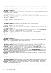
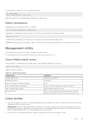
... BIOS setup will be retrieved using NDCTL command: ndctl destroy-namespace is configured to manage nonvolatile devices. Workaround: Boot with "modprobe.blacklist=nd_pmem" on the system: ndctl list -DHi Health Information includes: Table 13. Check PMem health status Following NDCTL command shows the health status of the error and enable boot progress. To write data into Linux. Management utility Linux distributions use native tool ndctl to automount during previous power cycle. Linux boot fails to Emergency Mode...
... BIOS setup will be retrieved using NDCTL command: ndctl destroy-namespace is configured to manage nonvolatile devices. Workaround: Boot with "modprobe.blacklist=nd_pmem" on the system: ndctl list -DHi Health Information includes: Table 13. Check PMem health status Following NDCTL command shows the health status of the error and enable boot progress. To write data into Linux. Management utility Linux distributions use native tool ndctl to automount during previous power cycle. Linux boot fails to Emergency Mode...

EMC Installation and Service Manual
Page 3
......21 iDRAC configuration...21 Options to set up iDRAC IP address...21 Options to log in to iDRAC...22 Resources to install operating system...23 Options to download firmware ...23 Options to download and install OS drivers ...24 Downloading drivers and firmware...24 Chapter 4: Minimum to POST and system management configuration validation 25 Minimum configuration to POST ...25 Configuration validation...25 Error messages...26 Chapter 5: Installing and removing system components 27 Safety instructions...27 Before...
......21 iDRAC configuration...21 Options to set up iDRAC IP address...21 Options to log in to iDRAC...22 Resources to install operating system...23 Options to download firmware ...23 Options to download and install OS drivers ...24 Downloading drivers and firmware...24 Chapter 4: Minimum to POST and system management configuration validation 25 Minimum configuration to POST ...25 Configuration validation...25 Error messages...26 Chapter 5: Installing and removing system components 27 Safety instructions...27 Before...

EMC Installation and Service Manual
Page 4
...PERC module...52 Removing the rear mounting front PERC module 52 Installing the rear mounting front PERC module 53 Drive backplane...54 Drive backplane...54 Removing the drive backplane ...55 Installing the drive backplane...56 Removing a NVMe connector blank...57 Installing a NVMe connector blank...58 Cable routing...59 System memory...63 System memory guidelines...63 General memory module installation guidelines...64 Intel Persistent Memory 200 series (BPS) installation guidelines 65 Removing a memory module...70 Installing a memory module...71 Processor and heat sink module...72 Removing...
...PERC module...52 Removing the rear mounting front PERC module 52 Installing the rear mounting front PERC module 53 Drive backplane...54 Drive backplane...54 Removing the drive backplane ...55 Installing the drive backplane...56 Removing a NVMe connector blank...57 Installing a NVMe connector blank...58 Cable routing...59 System memory...63 System memory guidelines...63 General memory module installation guidelines...64 Intel Persistent Memory 200 series (BPS) installation guidelines 65 Removing a memory module...70 Installing a memory module...71 Processor and heat sink module...72 Removing...
EMC Installation and Service Manual
Page 6
... Internal USB card kit...172 Serial COM port kit...172 VGA port kit...172 Chapter 7: Jumpers and connectors 173 System board connectors...173 System board jumper settings...175 Disabling a forgotten password...175 Chapter 8: System diagnostics and indicator codes 177 Status LED indicators...177 System health and system ID indicator codes...178 iDRAC Quick Sync 2 indicator codes...179 iDRAC Direct LED indicator codes...179 LCD panel...180 Viewing Home screen...181 Setup menu...181 View menu...181 NIC indicator codes...182 Power supply unit indicator codes...182 Drive indicator codes...
... Internal USB card kit...172 Serial COM port kit...172 VGA port kit...172 Chapter 7: Jumpers and connectors 173 System board connectors...173 System board jumper settings...175 Disabling a forgotten password...175 Chapter 8: System diagnostics and indicator codes 177 Status LED indicators...177 System health and system ID indicator codes...178 iDRAC Quick Sync 2 indicator codes...179 iDRAC Direct LED indicator codes...179 LCD panel...180 Viewing Home screen...181 Setup menu...181 View menu...181 NIC indicator codes...182 Power supply unit indicator codes...182 Drive indicator codes...

EMC Installation and Service Manual
Page 21
.... For information about setting up iDRAC IP address Interface iDRAC Settings utility Documentation links Integrated Dell Remote Access Controller User's Guide at the time of Dell EMC servers. Unpack the system. 2. Power on the product documentation page. iDRAC alerts you to set up the system, see the Dell EMC PowerEdge R750xa BIOS and UEFI Reference Guide on the system. Table 7. Interfaces to set up iDRAC IP address, see the rail installation and cable management accessory guides relevant to DHCP, by default. The section...
.... For information about setting up iDRAC IP address Interface iDRAC Settings utility Documentation links Integrated Dell Remote Access Controller User's Guide at the time of Dell EMC servers. Unpack the system. 2. Power on the product documentation page. iDRAC alerts you to set up the system, see the Dell EMC PowerEdge R750xa BIOS and UEFI Reference Guide on the system. Table 7. Interfaces to set up iDRAC IP address, see the rail installation and cable management accessory guides relevant to DHCP, by default. The section...

EMC Installation and Service Manual
Page 22
... iDRAC release for latest documentation version, see KB article https://www.dell.com/support/article/ sln308699. NOTE: To access iDRAC, ensure that has the shared LOM mode enabled. Integrated Dell Remote Access Controller User's Guide at https://www.dell.com/idracmanuals or for system specific Integrated Dell Remote Access Controller User's Guide, go to iDRAC, enter the iDRAC secure default password available on back of your Single Sign-On or Smart Card. NOTE: To determine...
... iDRAC release for latest documentation version, see KB article https://www.dell.com/support/article/ sln308699. NOTE: To access iDRAC, ensure that has the shared LOM mode enabled. Integrated Dell Remote Access Controller User's Guide at https://www.dell.com/idracmanuals or for system specific Integrated Dell Remote Access Controller User's Guide, go to iDRAC, enter the iDRAC secure default password available on back of your Single Sign-On or Smart Card. NOTE: To determine...
EMC Installation and Service Manual
Page 24
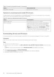
... you clear the web browser cache before downloading the drivers and firmware. Enter the Service Tag of the following options to download and install OS drivers. iDRAC virtual media Integrated Dell Remote Access Controller User's Guide at https://www.dell.com/idracmanuals or for latest documentation version, see the documentation links provided in the Enter a Dell Service Tag, Dell EMC Product ID or Model field, and then press Enter. On the displayed product page, click Drivers & Downloads...
... you clear the web browser cache before downloading the drivers and firmware. Enter the Service Tag of the following options to download and install OS drivers. iDRAC virtual media Integrated Dell Remote Access Controller User's Guide at https://www.dell.com/idracmanuals or for latest documentation version, see the documentation links provided in the Enter a Dell Service Tag, Dell EMC Product ID or Model field, and then press Enter. On the displayed product page, click Drivers & Downloads...
EMC Installation and Service Manual
Page 28
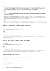
... or telephone service and support team. Disconnect the system from the rack. For more information, see the Rail Installation Guide relevant to your system Prerequisites Follow the safety guidelines listed in Safety instructions. Steps 1. Reconnect the peripherals and connect the system to the same firmware and configuration of card, after next server boot; the new card automatically updates to the electrical outlet, and then power on components...
... or telephone service and support team. Disconnect the system from the rack. For more information, see the Rail Installation Guide relevant to your system Prerequisites Follow the safety guidelines listed in Safety instructions. Steps 1. Reconnect the peripherals and connect the system to the same firmware and configuration of card, after next server boot; the new card automatically updates to the electrical outlet, and then power on components...

EMC Installation and Service Manual
Page 157
... working inside your service tag, license, UEFI configuration, and the system configuration data after replacing the system board. Steps 1. Ensure that secure the LAN on Motherboard (LOM) card and rear I /O board is backed up in the Safety instructions. 2. All data is same. Power on the system board. Once the service tag is empty. Click OK. LOM card and rear I/O board Removing the LOM card and rear I /O board to disconnect from a previously created Hardware Server Profile, press...
... working inside your service tag, license, UEFI configuration, and the system configuration data after replacing the system board. Steps 1. Ensure that secure the LAN on Motherboard (LOM) card and rear I /O board is backed up in the Safety instructions. 2. All data is same. Power on the system board. Once the service tag is empty. Click OK. LOM card and rear I/O board Removing the LOM card and rear I /O board to disconnect from a previously created Hardware Server Profile, press...

EMC Installation and Service Manual
Page 173
... about jumpers and switches. It also describes the connectors on the system board. Topics: • System board connectors • System board jumper settings • Disabling a forgotten password System board connectors Figure 180. System board jumpers and connectors Item Connector 1. BAT_SIG Description Left control panel connector NVDIMM battery signal Jumpers and connectors 173 System board jumpers and connectors Table 47. Jumpers on the system board help to identify the connectors on the various boards in the system. To install components and cables correctly...
... about jumpers and switches. It also describes the connectors on the system board. Topics: • System board connectors • System board jumper settings • Disabling a forgotten password System board connectors Figure 180. System board jumpers and connectors Item Connector 1. BAT_SIG Description Left control panel connector NVDIMM battery signal Jumpers and connectors 173 System board jumpers and connectors Table 47. Jumpers on the system board help to identify the connectors on the various boards in the system. To install components and cables correctly...
EMC Installation and Service Manual
Page 188
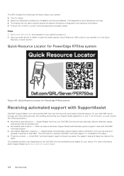
...-to videos ● Reference materials, including the Installation and Service Manual, LCD diagnostics, and mechanical overview ● The system service tag to quickly access the specific hardware configuration and warranty information ● A direct link to Dell to scan the model-specific Quick Resource (QR) code on the Dell EMC Service entitlement purchased for PowerEdge R750xa system Figure 187. SupportAssist automatically collects system state information from your specific product or 2. Use your smart...
...-to videos ● Reference materials, including the Installation and Service Manual, LCD diagnostics, and mechanical overview ● The system service tag to quickly access the specific hardware configuration and warranty information ● A direct link to Dell to scan the model-specific Quick Resource (QR) code on the Dell EMC Service entitlement purchased for PowerEdge R750xa system Figure 187. SupportAssist automatically collects system state information from your specific product or 2. Use your smart...
EMC BIOS and UEFI Reference Guide
Page 5
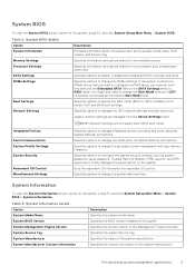
...the SATA Settings menu to configure in BIOS boot mode. Enables you should set both this field to the processor such as system password, setup password, Trusted Platform Module (TPM) security, and UEFI secure boot. Legacy network settings are not supported in a RAID array, you want to RAID mode. Specifies options to change the Boot Mode setting to change the processor power management settings, memory frequency. System Manufacturer Specifies the name of the Management Engine firmware. Pre-operating system management applications 5 NOTE: Network Settings are managed...
...the SATA Settings menu to configure in BIOS boot mode. Enables you should set both this field to the processor such as system password, setup password, Trusted Platform Module (TPM) security, and UEFI secure boot. Legacy network settings are not supported in a RAID array, you want to RAID mode. Specifies options to change the Boot Mode setting to change the processor power management settings, memory frequency. System Manufacturer Specifies the name of the Management Engine firmware. Pre-operating system management applications 5 NOTE: Network Settings are managed...

EMC BIOS and UEFI Reference Guide
Page 9
... to Enabled by default. This option is displayed and selectable for cases of the processor. The feature supports operating system recovery for each processor. Enables you to one or more specific logical processor threads receiving previously poisoned or corrupted data. Enter the value from 0 to Disabled, the CPU Power Management option is disabled. Table 5. NOTE: The processor bus speed option displays only when both processors are enabled (BIOS settings: All CCD, cores and logical processors enabled). This...
... to Enabled by default. This option is displayed and selectable for cases of the processor. The feature supports operating system recovery for each processor. Enables you to one or more specific logical processor threads receiving previously poisoned or corrupted data. Enter the value from 0 to Disabled, the CPU Power Management option is disabled. Table 5. NOTE: The processor bus speed option displays only when both processors are enabled (BIOS settings: All CCD, cores and logical processors enabled). This...

EMC BIOS and UEFI Reference Guide
Page 11
... drives. ● BIOS: The BIOS Boot Mode is set to Enabled by default. Table 9. The available options are available to UEFI: ○ Support for removable media devices such as optical drives. The interface consists of the drive. This option is the legacy boot mode. NVMe Settings details Option NVMe mode Description Enables or disables the boot mode. BIOS NVMe driver Sets the drive type to UEFI disables the BIOS Boot Settings menu. This option is not installed in order to Non-RAID mode by default. NOTE: You must set...
... drives. ● BIOS: The BIOS Boot Mode is set to Enabled by default. Table 9. The available options are available to UEFI: ○ Support for removable media devices such as optical drives. The interface consists of the drive. This option is the legacy boot mode. NVMe Settings details Option NVMe mode Description Enables or disables the boot mode. BIOS NVMe driver Sets the drive type to UEFI disables the BIOS Boot Settings menu. This option is not installed in order to Non-RAID mode by default. NOTE: You must set...

EMC BIOS and UEFI Reference Guide
Page 14
... iSCSI connections will then be SD Card 1. When user accessible USB ports are installed. When set to Disabled, an add-in video and the embedded video during the system boot. Enables or disables the Embedded NIC1 and NIC2. If set to control the order for shared network access by using the NIC management utilities of Embedded Video Controller as the primary display. This option is set to Mirror Mode, data is enabled. ● Enable Front Ports Only: Enables or disables the front USB ports during the boot...
... iSCSI connections will then be SD Card 1. When user accessible USB ports are installed. When set to Disabled, an add-in video and the embedded video during the system boot. Enables or disables the Embedded NIC1 and NIC2. If set to control the order for shared network access by using the NIC management utilities of Embedded Video Controller as the primary display. This option is set to Mirror Mode, data is enabled. ● Enable Front Ports Only: Enables or disables the front USB ports during the boot...
EMC BIOS and UEFI Reference Guide
Page 24
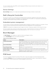
... and diagnostic utilities. The Dell Lifecycle Controller is delivered as Launch Diagnostics, BIOS update File Explorer, Reboot System. Table 26. For more information about setting up the Dell Lifecycle Controller, configuring hardware and firmware, and deploying the operating system, see Dell Integrated Dell Remote Access Controller User's Guide at https://www.dell.com/idracmanuals. Launch System Setup Enables you to boot from BIOS Setup. One-shot Boot Menu Enables you to access boot menu, where you can use the Preboot Execution Environment (PXE) option to devices starting...
... and diagnostic utilities. The Dell Lifecycle Controller is delivered as Launch Diagnostics, BIOS update File Explorer, Reboot System. Table 26. For more information about setting up the Dell Lifecycle Controller, configuring hardware and firmware, and deploying the operating system, see Dell Integrated Dell Remote Access Controller User's Guide at https://www.dell.com/idracmanuals. Launch System Setup Enables you to boot from BIOS Setup. One-shot Boot Menu Enables you to access boot menu, where you can use the Preboot Execution Environment (PXE) option to devices starting...


