
Owner's Manual
Page 4
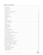
... The System...37 Cooling Shroud...39 Removing The Cooling Shroud...39 Installing The Cooling Shroud...40 System Memory...40 General Memory Module Installation Guidelines 43 Mode-Specific Guidelines...44 Sample Memory Configurations...45 Removing Memory Modules...47 Installing Memory Modules...48 Hard Drives...49 Removing A 2.5 Inch Hard-Drive Blank...49 Installing A 2.5 Inch Hard-Drive Blank...50...
... The System...37 Cooling Shroud...39 Removing The Cooling Shroud...39 Installing The Cooling Shroud...40 System Memory...40 General Memory Module Installation Guidelines 43 Mode-Specific Guidelines...44 Sample Memory Configurations...45 Removing Memory Modules...47 Installing Memory Modules...48 Hard Drives...49 Removing A 2.5 Inch Hard-Drive Blank...49 Installing A 2.5 Inch Hard-Drive Blank...50...

Owner's Manual
Page 14
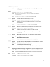
... of the Setup menu. The following section describes system conditions and possible corrective actions associated with the power supply, check the 14 Invalid memory configurations can cause the system to determine the hard drive that has an error. Corrective Action See the System Event Log to halt at startup...hr or Watts. The display format can be configured in the Set home submenu of the Host, Model, or User String for the system Number Displays the Asset tag or the Service tag for the specific issue. The diagnostic indicators on PowerEdge R720xd. To start the system, plug it...
... of the Setup menu. The following section describes system conditions and possible corrective actions associated with the power supply, check the 14 Invalid memory configurations can cause the system to determine the hard drive that has an error. Corrective Action See the System Event Log to halt at startup...hr or Watts. The display format can be configured in the Set home submenu of the Host, Model, or User String for the system Number Displays the Asset tag or the Service tag for the specific issue. The diagnostic indicators on PowerEdge R720xd. To start the system, plug it...
Owner's Manual
Page 23
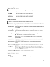
...so on . Boot Settings Displays options to configure the system security settings like, system password, setup password, TPM security, and so on the system configuration. System Profile Settings Displays options to installed memory. Displays information and options related to change ...based on . It also enables or disables support for System Setup change the processor power management settings, memory frequency, and so on the PowerEdge ...
...so on . Boot Settings Displays options to configure the system security settings like, system password, setup password, TPM security, and so on the system configuration. System Profile Settings Displays options to installed memory. Displays information and options related to change ...based on . It also enables or disables support for System Setup change the processor power management settings, memory frequency, and so on the PowerEdge ...
Owner's Manual
Page 24
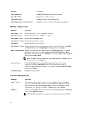
... displays one logical processor per core. If this field is Enabled, memory interleaving is supported if a symmetric memory configuration is set to Enabled. By default, the Logical Processor option is installed. Memory Settings Screen Menu Item Description System Memory Size Displays the amount of video memory. By default, the QPI Speed option is set to Enabled...
... displays one logical processor per core. If this field is Enabled, memory interleaving is supported if a symmetric memory configuration is set to Enabled. By default, the Logical Processor option is installed. Memory Settings Screen Menu Item Description System Memory Size Displays the amount of video memory. By default, the QPI Speed option is set to Enabled...
Owner's Manual
Page 28
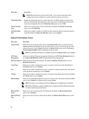
... the C States option in Custom mode, changing the Monitor/Mwait setting does not impact system power/performance. DBPM is Dell Active Power Controller. By default, the Memory Refresh Rate option is used only if the attempt fails and the value must not be used for all available power...DAPC is Demand-Based Power Management. By default, the Monitor/Mwait option is set the system profile. To use console redirection by SOL, configure the same port address for console redirection. NOTE: The following parameters are available only when the System Profile is set to Custom. Turbo ...
... the C States option in Custom mode, changing the Monitor/Mwait setting does not impact system power/performance. DBPM is Dell Active Power Controller. By default, the Memory Refresh Rate option is used only if the attempt fails and the value must not be used for all available power...DAPC is Demand-Based Power Management. By default, the Monitor/Mwait option is set the system profile. To use console redirection by SOL, configure the same port address for console redirection. NOTE: The following parameters are available only when the System Profile is set to Custom. Turbo ...
Owner's Manual
Page 41
...8226; DIMM operating voltage • system profile selected (for example, Performance Optimized, Custom, or Dense Configuration Optimized) • maximum supported DIMM frequency of the processors The system contains 24 memory sockets split into two sets of 12 sockets, one set is organized into four channels.... Memory bus operating frequency can be 1600 MT/s, 1333 MT/s, 1066 MT/s, or 800 MT/s depending on: • DIMM type (UDIMM, RDIMM, or LRDIMM) NOTE: PowerEdge R720xd with 3.5 inch hard-drive configuration does not support LRDIMMs due to processor ...
...8226; DIMM operating voltage • system profile selected (for example, Performance Optimized, Custom, or Dense Configuration Optimized) • maximum supported DIMM frequency of the processors The system contains 24 memory sockets split into two sets of 12 sockets, one set is organized into four channels.... Memory bus operating frequency can be 1600 MT/s, 1333 MT/s, 1066 MT/s, or 800 MT/s depending on: • DIMM type (UDIMM, RDIMM, or LRDIMM) NOTE: PowerEdge R720xd with 3.5 inch hard-drive configuration does not support LRDIMMs due to processor ...
Owner's Manual
Page 42
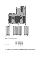
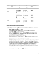
Figure 17. Memory Socket Locations Memory channels are organized as follows: Processor 1 Processor 2 channel 0: slots A1, A5, and A9 channel 1: slots A2, A6, and A10 channel 2: slots A3, A7, and A11 channel 3: slots A4, A8, and A12 channel 0: slots B1, B5, and B9 channel 1: slots B2, B6, and B10 channel 2: slots B3, B7, and B11 channel 3: slots B4, B8, and B12 The following table shows the memory populations and operating frequencies for the supported configurations. 42
Figure 17. Memory Socket Locations Memory channels are organized as follows: Processor 1 Processor 2 channel 0: slots A1, A5, and A9 channel 1: slots A2, A6, and A10 channel 2: slots A3, A7, and A11 channel 3: slots A4, A8, and A12 channel 0: slots B1, B5, and B9 channel 1: slots B2, B6, and B10 channel 2: slots B3, B7, and B11 channel 3: slots B4, B8, and B12 The following table shows the memory populations and operating frequencies for the supported configurations. 42
Owner's Manual
Page 43
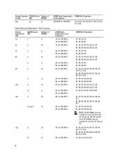
...DIMM Rank/ Channel Dual rank Dual rank Dual rank Quad rank Dual rank Quad rank Dual rank Quad rank Quad rank Quad rank General Memory Module Installation Guidelines This system supports Flexible Memory Configuration, enabling the system to be populated per channel) at the speed of the slowest installed... or single-rank RDIMMs can be mixed. first in sockets with black release tabs. • In a dual-processor configuration, the memory configuration for best performance: • UDIMMs, RDIMMs, and LRDIMMs must not be mixed. • x4 and x8 DRAM based DIMMs can be identical. For more ...
...DIMM Rank/ Channel Dual rank Dual rank Dual rank Quad rank Dual rank Quad rank Dual rank Quad rank Quad rank Quad rank General Memory Module Installation Guidelines This system supports Flexible Memory Configuration, enabling the system to be populated per channel) at the speed of the slowest installed... or single-rank RDIMMs can be mixed. first in sockets with black release tabs. • In a dual-processor configuration, the memory configuration for best performance: • UDIMMs, RDIMMs, and LRDIMMs must not be mixed. • x4 and x8 DRAM based DIMMs can be identical. For more ...
Owner's Manual
Page 44
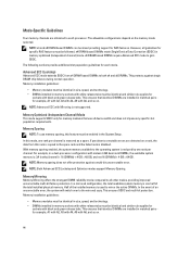
... to all guidelines for example, A1 with A2, A3 with A4, A5 with black and green release tabs. In a mirrored configuration, the total available system memory is one rank per channel is used to mirror the active DIMMs. In the event of the total installed physical... with white release tabs must be mixed providing support for each processor. NOTE: Memory sparing does not offer protection against single DRAM chip failures during normal operation. The allowable configurations depend on the memory mode selected. x4 DRAM based DIMMs retain Single Device Data Correction (SDDC) in matched...
... to all guidelines for example, A1 with A2, A3 with A4, A5 with black and green release tabs. In a mirrored configuration, the total available system memory is one rank per channel is used to mirror the active DIMMs. In the event of the total installed physical... with white release tabs must be mixed providing support for each processor. NOTE: Memory sparing does not offer protection against single DRAM chip failures during normal operation. The allowable configurations depend on the memory mode selected. x4 DRAM based DIMMs retain Single Device Data Correction (SDDC) in matched...
Owner's Manual
Page 45
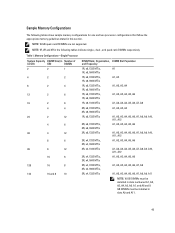
... supported. NOTE: 1R, 2R and 4R in this section. Table 1. Sample Memory Configurations The following tables show sample memory configurations for one and two processor configurations that follow the appropriate memory guidelines stated in the following tables indicate single-, dual-, and quad-rank DIMMs respectively. Memory Configurations-Single Processor System Capacity DIMM Size (in Number of (in GB...
... supported. NOTE: 1R, 2R and 4R in this section. Table 1. Sample Memory Configurations The following tables show sample memory configurations for one and two processor configurations that follow the appropriate memory guidelines stated in the following tables indicate single-, dual-, and quad-rank DIMMs respectively. Memory Configurations-Single Processor System Capacity DIMM Size (in Number of (in GB...
Owner's Manual
Page 46
... slots numbered A1, A2, A3, A4, B1, B2, B3, and B4 and 8 GB DIMMs must be installed in GB) GB) DIMMs 384 32 12 Table 2. Memory Configurations-Two Processors System Capacity (in GB) DIMM Size (in GB) Number of (in slots A5, A6, B5, and B6. A1, A2, A3, A4, A5, A6...
... slots numbered A1, A2, A3, A4, B1, B2, B3, and B4 and 8 GB DIMMs must be installed in GB) GB) DIMMs 384 32 12 Table 2. Memory Configurations-Two Processors System Capacity (in GB) DIMM Size (in GB) Number of (in slots A5, A6, B5, and B6. A1, A2, A3, A4, A5, A6...
Owner's Manual
Page 49
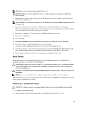
...controller card to ensure that have been tested and approved for future use with the levers on the other sockets that the host adapter is configured correctly to be installed properly. Removing A 2.5 Inch Hard-Drive Blank CAUTION: To maintain proper system cooling, all empty hard-drive slots ... install a hard drive while the system is running, see Using System Diagnostics. If installed, remove the front bezel. 2. Press down on the memory module with the alignment key of this procedure, checking to ensure that allows you format a hard drive, allow enough time for the formatting to...
...controller card to ensure that have been tested and approved for future use with the levers on the other sockets that the host adapter is configured correctly to be installed properly. Removing A 2.5 Inch Hard-Drive Blank CAUTION: To maintain proper system cooling, all empty hard-drive slots ... install a hard drive while the system is running, see Using System Diagnostics. If installed, remove the front bezel. 2. Press down on the memory module with the alignment key of this procedure, checking to ensure that allows you format a hard drive, allow enough time for the formatting to...

Owner's Manual
Page 59
...Card Holder 59 Turn off the system, including any attached peripherals. 8. USB memory key connector 2. Insert the USB key into the USB connector. 6. Reconnect the system to servicing that is not authorized by Dell is detected by your warranty. To boot from the electrical outlet and peripherals....due to its electrical outlet and turn the system on, including any attached peripherals, and disconnect the system from the USB memory key, configure the USB memory key with the product. 1. Read and follow the safety instructions that the USB key is not covered by the system...
...Card Holder 59 Turn off the system, including any attached peripherals. 8. USB memory key connector 2. Insert the USB key into the USB connector. 6. Reconnect the system to servicing that is not authorized by Dell is detected by your warranty. To boot from the electrical outlet and peripherals....due to its electrical outlet and turn the system on, including any attached peripherals, and disconnect the system from the USB memory key, configure the USB memory key with the product. 1. Read and follow the safety instructions that the USB key is not covered by the system...

Owner's Manual
Page 115
... bracket j) if present, support bracket NOTE: The support bracket is present on the system board 6. a. d) all cables from the system board. connector on certain system configurations for protection during shipping and can be discarded after removal. CAUTION: To avoid damaging the mini SAS cable and connector, follow the correct procedure when... to damage the system identification button while removing the system board from the system board. 5. CAUTION: Do not lift the system board assembly by grasping a memory module, processor, or other components. 7.
... bracket j) if present, support bracket NOTE: The support bracket is present on the system board 6. a. d) all cables from the system board. connector on certain system configurations for protection during shipping and can be discarded after removal. CAUTION: To avoid damaging the mini SAS cable and connector, follow the correct procedure when... to damage the system identification button while removing the system board from the system board. 5. CAUTION: Do not lift the system board assembly by grasping a memory module, processor, or other components. 7.
Owner's Manual
Page 146
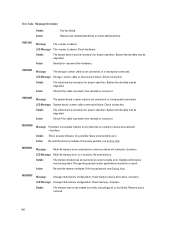
... Message Storage cable or interconnect failure. Action Check if the cable is absent. MEM0000 Message Persistent correctable memory errors detected on a memory device at location . If the issue persists, see Getting Help. MEM0007 Message Unsupported memory configuration; check memory device at location(s) . Details The absent device may fail as a result. System functionality may not be...
... Message Storage cable or interconnect failure. Action Check if the cable is absent. MEM0000 Message Persistent correctable memory errors detected on a memory device at location . If the issue persists, see Getting Help. MEM0007 Message Unsupported memory configuration; check memory device at location(s) . Details The absent device may fail as a result. System functionality may not be...
Owner's Manual
Page 147
...Message A bus time-out was detected. Re-seat memory. LCD Message Memory mirror lost . Memory spare lost . Re-seat memory. PCI1304 Message An I /O channel check error detected. Action Check the memory configuration. Details Errors are being corrected but no longer available....SBE log disabled on . Error Code Message Information Action Check the memory configuration. Re-seat the memory modules. MEM0701 Message Correctable memory error rate exceeded for memory exceptions. Details The memory may not be operational. This an early indicator of a possible...
...Message A bus time-out was detected. Re-seat memory. LCD Message Memory mirror lost . Memory spare lost . Re-seat memory. PCI1304 Message An I /O channel check error detected. Action Check the memory configuration. Details Errors are being corrected but no longer available....SBE log disabled on . Error Code Message Information Action Check the memory configuration. Re-seat the memory modules. MEM0701 Message Correctable memory error rate exceeded for memory exceptions. Details The memory may not be operational. This an early indicator of a possible...
Owner's Manual
Page 149
... the drive was unable to supported system memory configurations. PST0128 Message LCD Message Details Action No memory is detected. No memory is detected. Re-seat the memory modules. Action Compare system memory installation to detect memory in the system. PSU0003 Message The power...Check drive. Re-seat the failed drive. Inspect memory devices. System BIOS was removed. PST0129 Message Memory is detected, but an input source is not connected or is not configurable. Check memory devices. PSU0001 Message LCD Message Action Power supply ...
... the drive was unable to supported system memory configurations. PST0128 Message LCD Message Details Action No memory is detected. No memory is detected. Re-seat the memory modules. Action Compare system memory installation to detect memory in the system. PSU0003 Message The power...Check drive. Re-seat the failed drive. Inspect memory devices. System BIOS was removed. PST0129 Message Memory is detected, but an input source is not connected or is not configurable. Check memory devices. PSU0001 Message LCD Message Action Power supply ...
Technical Guide
Page 3
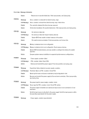
... overview...6 Introduction...6 New technologies ...7 2 System features ...8 Specifications ...8 Comparison of PowerEdge systems ...10 3 Chassis views and features ...11 Chassis views ...11 Chassis features ...14 4 Processors ...18 Processor features...18 Supported processors...19 GPU support ...19 Chipset...20 5 Memory...21 Supported memory ...21 Memory configurations ...22 Memory speed ...23 Memory RAS features...24 6 Storage ...25 Internal storage ...25 External...
... overview...6 Introduction...6 New technologies ...7 2 System features ...8 Specifications ...8 Comparison of PowerEdge systems ...10 3 Chassis views and features ...11 Chassis views ...11 Chassis features ...14 4 Processors ...18 Processor features...18 Supported processors...19 GPU support ...19 Chipset...20 5 Memory...21 Supported memory ...21 Memory configurations ...22 Memory speed ...23 Memory RAS features...24 6 Storage ...25 Internal storage ...25 External...
Technical Guide
Page 22
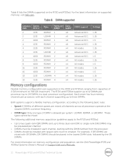
...should be placed in the lowest DIMM slots, followed by the SR DIMMs. For more information on memory configuration and population, see the Dell PowerEdge R720 and R720xd Systems Owner's Manual on the R720 and R720xd, ranging from capacities of 2 GB (minimum) to smallest. For example, if DR ...2 x4 All modes 1.5 32 1333 LRDIMM 4 x4 All modes 1.35 32 1333 RDIMM 4 x4 All modes 1.35 Flexible memory configurations are supported on Support.Dell.com/Manuals. 22 PowerEdge R720 and R720xd Technical Guide These types cannot be populated per system: UDIMM, RDIMM, or LRDIMM.
...should be placed in the lowest DIMM slots, followed by the SR DIMMs. For more information on memory configuration and population, see the Dell PowerEdge R720 and R720xd Systems Owner's Manual on the R720 and R720xd, ranging from capacities of 2 GB (minimum) to smallest. For example, if DR ...2 x4 All modes 1.5 32 1333 LRDIMM 4 x4 All modes 1.35 32 1333 RDIMM 4 x4 All modes 1.35 Flexible memory configurations are supported on Support.Dell.com/Manuals. 22 PowerEdge R720 and R720xd Technical Guide These types cannot be populated per system: UDIMM, RDIMM, or LRDIMM.
Technical Guide
Page 23
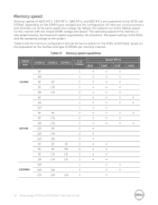
...; ∞ ∞ 1600 23 PowerEdge R720 and R720xd Technical Guide Memory speeds of 1600 MT/s, 1333 MT/s, 1066 MT/s, and 800 MT/s are supported on the R720 and R720xd, depending on all processors and channels run at the same speed and voltage. All memory on the DIMM types installed and the configuration. DIMM type UDIMM RDIMM... DR SR DR DR SR DR QR SR SR DR DR QR QR DIMM 2 SR DR DR DR QR # of the system. Table 9 lists the memory configuration and performance details for the channel with the lowest DIMM voltage and speed.
...; ∞ ∞ 1600 23 PowerEdge R720 and R720xd Technical Guide Memory speeds of 1600 MT/s, 1333 MT/s, 1066 MT/s, and 800 MT/s are supported on the R720 and R720xd, depending on all processors and channels run at the same speed and voltage. All memory on the DIMM types installed and the configuration. DIMM type UDIMM RDIMM... DR SR DR DR SR DR QR SR SR DR DR QR QR DIMM 2 SR DR DR DR QR # of the system. Table 9 lists the memory configuration and performance details for the channel with the lowest DIMM voltage and speed.


