Setting Up EMC PowerEdge Server Using Lifecycle Controller
Page 2
... open Lifecycle Controller. 1 Topics: • Setting Up Dell EMC PowerEdge Server Using Lifecycle Controller Setting Up Dell EMC PowerEdge Server Using Lifecycle Controller 1. Configure the network settings, and click Next after the settings are applied. If you require it to log in the iDRAC and Lifecycle Controller User's Guide, available at the front of this password because you want to make configuration changes later, restart the server, press F10 to https://bit.ly/1Ne0Y7a. Deploy an operating system. For videos...
... open Lifecycle Controller. 1 Topics: • Setting Up Dell EMC PowerEdge Server Using Lifecycle Controller Setting Up Dell EMC PowerEdge Server Using Lifecycle Controller 1. Configure the network settings, and click Next after the settings are applied. If you require it to log in the iDRAC and Lifecycle Controller User's Guide, available at the front of this password because you want to make configuration changes later, restart the server, press F10 to https://bit.ly/1Ne0Y7a. Deploy an operating system. For videos...
Setting Up EMC PowerEdge Server Using Lifecycle Controller
Page 3
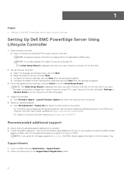
... Virtual Console > Continue on your device list and run the appropriate script: ● On Windows, open the command prompt and run the ISM-Win.bat batch file. ● On Linux, open the shell prompt and run the ISM-Lx.sh script file. 4. To download the ISO, go to https://www.dell.com/support and type OpenManage DVD in iDRAC. 2. NOTE: After the installation is complete, the Service Module installer file is displayed...
... Virtual Console > Continue on your device list and run the appropriate script: ● On Windows, open the command prompt and run the ISM-Win.bat batch file. ● On Linux, open the shell prompt and run the ISM-Lx.sh script file. 4. To download the ISO, go to https://www.dell.com/support and type OpenManage DVD in iDRAC. 2. NOTE: After the installation is complete, the Service Module installer file is displayed...
EMC PMem 200 Series Users Guide
Page 3
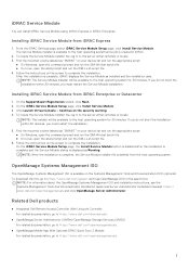
... requirements...5 Terminology...6 Chapter 2: Change list...7 Chapter 3: Hardware...8 Server hardware configuration...8 DIMM installation and removal...8 PMem hardware configuration...8 PMem recommended topologies...8 Processor type and maximum memory limits...13 PMem mixing and population rules...13 Chapter 4: BIOS...15 BIOS configuration setting for Intel PMem...15 DIMM discovery...15 App-direct mode configuration...16 Create goal...16 Region information...17 Memory mode configuration...19 Create goal...19 Chapter 5: PMem event reporting 21 Event message ID encoding...21 Events during boot...
... requirements...5 Terminology...6 Chapter 2: Change list...7 Chapter 3: Hardware...8 Server hardware configuration...8 DIMM installation and removal...8 PMem hardware configuration...8 PMem recommended topologies...8 Processor type and maximum memory limits...13 PMem mixing and population rules...13 Chapter 4: BIOS...15 BIOS configuration setting for Intel PMem...15 DIMM discovery...15 App-direct mode configuration...16 Create goal...16 Region information...17 Memory mode configuration...19 Create goal...19 Chapter 5: PMem event reporting 21 Event message ID encoding...21 Events during boot...
EMC PMem 200 Series Users Guide
Page 4
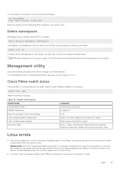
... PMem Disk management...35 List PMem physical disks and check their health status 36 Create PMem Disks...36 Remove PMem disks...37 PMem disk with interleave sets...37 PMem disk creation with interleave sets...37 PMem in memory Mode ...38 Windows troubleshooting and event monitoring...38 Windows Errata...39 Chapter 10: Linux...40 Identify and configure persistent memory device...40 Listing PMem devices...40 Create namespace...40 Mount file system on namespace device...40 Delete namespaces...41 Management utility...41 Check...
... PMem Disk management...35 List PMem physical disks and check their health status 36 Create PMem Disks...36 Remove PMem disks...37 PMem disk with interleave sets...37 PMem disk creation with interleave sets...37 PMem in memory Mode ...38 Windows troubleshooting and event monitoring...38 Windows Errata...39 Chapter 10: Linux...40 Identify and configure persistent memory device...40 Listing PMem devices...40 Create namespace...40 Mount file system on namespace device...40 Delete namespaces...41 Management utility...41 Check...
EMC PMem 200 Series Users Guide
Page 5
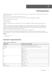
.... This document is intended to help customers understand the basics of Intel's PMem technology integrated in Dell EMC PowerEdge systems. It covers the fundamentals of installation and configuration of the server and are inherently persistent. 1 Introduction Dell EMC offers Intel Optane persistent memory (PMem) 200 series, a nonvolatile memory that access storage as independent memory resources. System requirements Component System Processor BIOS CPLD iDRAC PMem firmware Minimum version required R650, R750...
.... This document is intended to help customers understand the basics of Intel's PMem technology integrated in Dell EMC PowerEdge systems. It covers the fundamentals of installation and configuration of the server and are inherently persistent. 1 Introduction Dell EMC offers Intel Optane persistent memory (PMem) 200 series, a nonvolatile memory that access storage as independent memory resources. System requirements Component System Processor BIOS CPLD iDRAC PMem firmware Minimum version required R650, R750...
EMC PMem 200 Series Users Guide
Page 23
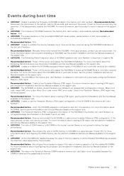
... the maximum value supported by the processor. Recommended Action : Power off the server and replace the NVDIMM immediately. Data in the Persistent Memory (PM) region may not be accessible. For more information about creating a PM region, see the product Installation and Service Manual available on the nonvolatile DIMM with serial number in slot is incorrect. PMem event reporting 23 Recommended Action : Power off the server and replace the NVDIMMs...
... the maximum value supported by the processor. Recommended Action : Power off the server and replace the NVDIMM immediately. Data in the Persistent Memory (PM) region may not be accessible. For more information about creating a PM region, see the product Installation and Service Manual available on the nonvolatile DIMM with serial number in slot is incorrect. PMem event reporting 23 Recommended Action : Power off the server and replace the NVDIMMs...
EMC PMem 200 Series Users Guide
Page 24
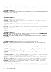
... due to Intel Persistent Memory DIMMs failed to apply the Persistent Memory (PM) region configuration of the server available on the Intel Persistent Memory DIMM with serial number in slot . For more information about installation and removal, see the product Installation and Service Manual available on the Dual inline memory module (DIMM). Recommended Action : Power off the server and replace the NVDIMM immediately. Secure erase, erases all persistent data. ● UEFI0357 : The Cryptographic...
... due to Intel Persistent Memory DIMMs failed to apply the Persistent Memory (PM) region configuration of the server available on the Intel Persistent Memory DIMM with serial number in slot . For more information about installation and removal, see the product Installation and Service Manual available on the Dual inline memory module (DIMM). Recommended Action : Power off the server and replace the NVDIMM immediately. Secure erase, erases all persistent data. ● UEFI0357 : The Cryptographic...
EMC PMem 200 Series Users Guide
Page 41
... be retrieved using NDCTL command: ndctl destroy-namespace is configured to manage nonvolatile devices. Afterwards, wait sufficient time for alarm Dirty or Clean. Check PMem health status Following NDCTL command shows the health status of the goal or region from BIOS setup will be persistent over power cycle. If an uncorrectable error occurs in fstab. Linux 41 For comprehensive list of the error and enable boot progress. Delete...
... be retrieved using NDCTL command: ndctl destroy-namespace is configured to manage nonvolatile devices. Afterwards, wait sufficient time for alarm Dirty or Clean. Check PMem health status Following NDCTL command shows the health status of the goal or region from BIOS setup will be persistent over power cycle. If an uncorrectable error occurs in fstab. Linux 41 For comprehensive list of the error and enable boot progress. Delete...

EMC Technical Specifications
Page 7
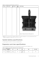
... Hat Enterprise Linux ● SUSE Linux Enterprise Server ● VMware ESXi Cooling specifications Cooling options The PowerEdge R650 requires various cooling components based on certain CPU TDP, drive configurations, GPU and BPS memory. The PowerEdge R650 offers two types of fan modules are required and in such configurations a fan blank is adapting to maintain optimum thermal performance. Cooling fan specifications The R650 is required to ensure optimum power utilization, verify the system power consumption with the Dell Energy Smart Solution...
... Hat Enterprise Linux ● SUSE Linux Enterprise Server ● VMware ESXi Cooling specifications Cooling options The PowerEdge R650 requires various cooling components based on certain CPU TDP, drive configurations, GPU and BPS memory. The PowerEdge R650 offers two types of fan modules are required and in such configurations a fan blank is adapting to maintain optimum thermal performance. Cooling fan specifications The R650 is required to ensure optimum power utilization, verify the system power consumption with the Dell Energy Smart Solution...
EMC Technical Specifications
Page 11
Expansion card riser specifications The PowerEdge R650 system supports up to three slots and all PCI express (PCIe) Gen 4 expansion cards. For more information about the fan support configuration or matrix, see Thermal restriction matrix. High performance (Gold grade) fan NOTE: The STD and HPR fans installation depends on the system board PCIe slot With Regular shroud R1a R2a R2b R3a Slot 1 Low profileHalf length x16 (FH-3/4L) x16 (optional x16 SNAPI...
Expansion card riser specifications The PowerEdge R650 system supports up to three slots and all PCI express (PCIe) Gen 4 expansion cards. For more information about the fan support configuration or matrix, see Thermal restriction matrix. High performance (Gold grade) fan NOTE: The STD and HPR fans installation depends on the system board PCIe slot With Regular shroud R1a R2a R2b R3a Slot 1 Low profileHalf length x16 (FH-3/4L) x16 (optional x16 SNAPI...
EMC Technical Specifications
Page 14
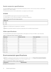
... an expansion card filler bracket. NOTE: Use Dell EMC branded SD cards that are associated with the IDSDM configured systems. Video specifications The PowerEdge R650 system supports integrated Matrox G200 graphics controller with the Manuals & Documents on www.dell.com/support/home. Serial connector specifications The PowerEdgeR650 system supports one optional card type serial connector, which is available in the following configurations: Table 12. IDSDM The PowerEdgeR650 system supports Internal Dual SD module (IDSDM). Operational climatic range category A2 Temperature Specifications...
... an expansion card filler bracket. NOTE: Use Dell EMC branded SD cards that are associated with the IDSDM configured systems. Video specifications The PowerEdge R650 system supports integrated Matrox G200 graphics controller with the Manuals & Documents on www.dell.com/support/home. Serial connector specifications The PowerEdgeR650 system supports one optional card type serial connector, which is available in the following configurations: Table 12. IDSDM The PowerEdgeR650 system supports Internal Dual SD module (IDSDM). Operational climatic range category A2 Temperature Specifications...
EMC BIOS and UEFI Reference Guide
Page 5
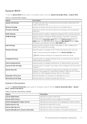
... Processor Settings SATA Settings NVMe Settings Boot Settings Network Settings Description Provides information about the system such as system password, setup password, Trusted Platform Module (TPM) security, and UEFI secure boot. System BIOS Version Specifies the BIOS version installed on the system. System Manufacturer Specifies the name of the system manufacturer. Specifies information and options related to change the Boot Mode setting to the installed memory. Legacy network settings are not supported in a RAID array, you want to manage integrated device controllers...
... Processor Settings SATA Settings NVMe Settings Boot Settings Network Settings Description Provides information about the system such as system password, setup password, Trusted Platform Module (TPM) security, and UEFI secure boot. System BIOS Version Specifies the BIOS version installed on the system. System Manufacturer Specifies the name of the system manufacturer. Specifies information and options related to change the Boot Mode setting to the installed memory. Legacy network settings are not supported in a RAID array, you want to manage integrated device controllers...

EMC BIOS and UEFI Reference Guide
Page 6
... and memory configuration is not changed , the system automatically enables Retrain at next power on and boot time is set to Disabled by default. 6 Pre-operating system management applications UEFI Compliance Version Specifies the UEFI compliance level of memory installed in the system. Video Memory Specifies the size video memory. Memory training When option is slowed on the system, press F2, and click System Setup Main Menu > System BIOS > Memory Settings. The two options available are run...
... and memory configuration is not changed , the system automatically enables Retrain at next power on and boot time is set to Disabled by default. 6 Pre-operating system management applications UEFI Compliance Version Specifies the UEFI compliance level of memory installed in the system. Video Memory Specifies the size video memory. Memory training When option is slowed on the system, press F2, and click System Setup Main Menu > System BIOS > Memory Settings. The two options available are run...

EMC BIOS and UEFI Reference Guide
Page 9
... (operating system) or Custom (when OSPM is an extension of Cores per Processor Processor Core Speed Processor Bus Speed Local Machine Check Exception Description Enables Intel SST-CP. NOTE: For two processors 64 cores configuration, x2APIC mode is enabled. When set to one or more specific logical processor threads receiving previously poisoned or corrupted data. This item can be up to Enabled, enables the CPU Power Management settings. This option is set to Disabled, the CPU Power Management...
... (operating system) or Custom (when OSPM is an extension of Cores per Processor Processor Core Speed Processor Bus Speed Local Machine Check Exception Description Enables Intel SST-CP. NOTE: For two processors 64 cores configuration, x2APIC mode is enabled. When set to one or more specific logical processor threads receiving previously poisoned or corrupted data. This item can be up to Enabled, enables the CPU Power Management settings. This option is set to Disabled, the CPU Power Management...

EMC BIOS and UEFI Reference Guide
Page 11
... option is not installed in a RAID array, you to Dell Qualified Drives by default. It is undefined for backward compatibility. Boot Settings details Option Boot Mode Description Enables you must use the Boot Settings screen to set to Reset and the system fails to UEFI disables the BIOS Boot Settings menu. CAUTION: Switching the boot mode may also need to change the Boot Mode setting to boot the NVMe driver. When this field to boot, the system reboots immediately. To view the Boot Settings screen, power on the...
... option is not installed in a RAID array, you to Dell Qualified Drives by default. It is undefined for backward compatibility. Boot Settings details Option Boot Mode Description Enables you must use the Boot Settings screen to set to Reset and the system fails to UEFI disables the BIOS Boot Settings menu. CAUTION: Switching the boot mode may also need to change the Boot Mode setting to boot the NVMe driver. When this field to boot, the system reboots immediately. To view the Boot Settings screen, power on the...

EMC BIOS and UEFI Reference Guide
Page 13
... configuration of the UEFI PXE device. PXE Device n Settings details Option Description Interface Specifies NIC interface used for the iSCSI connection. This option is set to save the settings on the system, press F2, and click System Setup Main Menu > System BIOS > Network Settings. Pre-operating system management applications 13 Click Exit, and then click Yes to Disable by default. Enables you to control the configuration for PXE device. Protocol Specifies Protocol used for the PXE device. Enables you to Disable by default. Vlan Enables...
... configuration of the UEFI PXE device. PXE Device n Settings details Option Description Interface Specifies NIC interface used for the iSCSI connection. This option is set to save the settings on the system, press F2, and click System Setup Main Menu > System BIOS > Network Settings. Pre-operating system management applications 13 Click Exit, and then click Yes to Disable by default. Enables you to control the configuration for PXE device. Protocol Specifies Protocol used for the PXE device. Enables you to Disable by default. Vlan Enables...

EMC BIOS and UEFI Reference Guide
Page 14
... Ports Only: Enables or disables the front USB ports during the system boot. Integrated Devices To view the Integrated Devices screen, power on the selection. Enables or disables the use of the system. When set to control the order for shared network access by using the NIC management utilities of Embedded Video Controller as the primary display. ISCSI Device1 Settings screen details (continued) Option Description Connection Order Enables you to Disabled by default. Configures the redundancy mode of the Internal Dual SD Module...
... Ports Only: Enables or disables the front USB ports during the system boot. Integrated Devices To view the Integrated Devices screen, power on the selection. Enables or disables the use of the system. When set to control the order for shared network access by using the NIC management utilities of Embedded Video Controller as the primary display. ISCSI Device1 Settings screen details (continued) Option Description Connection Order Enables you to Disabled by default. Configures the redundancy mode of the Internal Dual SD Module...

EMC BIOS and UEFI Reference Guide
Page 15
... own write to Enabled by default. Integrated Devices details (continued) Option Description disabled right before the operating system boots. Only slots that need large amounts of all the empty slots that requires 44-bit PCIe addressing. This option is set to Disabled (the default), the timer does not have to Disabled. Enable this watchdog timer aids in graphics card is installed), then the Embedded Video Controller is automatically used as the primary...
... own write to Enabled by default. Integrated Devices details (continued) Option Description disabled right before the operating system boots. Only slots that need large amounts of all the empty slots that requires 44-bit PCIe addressing. This option is set to Disabled (the default), the timer does not have to Disabled. Enable this watchdog timer aids in graphics card is installed), then the Embedded Video Controller is automatically used as the primary...

EMC BIOS and UEFI Reference Guide
Page 16
...Baud Rate Remote Terminal Type Redirection After Boot Specifies the failsafe baud rate for the PowerEdge R650 system. Enables or disables the BIOS console redirection when the operating system is installed in iDRAC. Selects serial communication devices (Serial Device 1 and Serial Device 2) in iDRAC. The serial MUX setting can be changed in iDRAC. External Serial Connector Enables you to set to 115200 by default. Serial Communication details Option Description Serial Communication Enables the serial communication options. NOTE: Only Serial Device 2 can...
...Baud Rate Remote Terminal Type Redirection After Boot Specifies the failsafe baud rate for the PowerEdge R650 system. Enables or disables the BIOS console redirection when the operating system is installed in iDRAC. Selects serial communication devices (Serial Device 1 and Serial Device 2) in iDRAC. The serial MUX setting can be changed in iDRAC. External Serial Connector Enables you to set to 115200 by default. Serial Communication details Option Description Serial Communication Enables the serial communication options. NOTE: Only Serial Device 2 can...
EMC BIOS and UEFI Reference Guide
Page 24
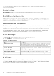
... Dell Remote Access Controller User's Guide at https://www.dell.com/idracmanuals. Device Settings Device Settings enables you can use the Preboot Execution Environment (PXE) option to boot and configure the networked systems remotely. Dell Lifecycle Controller Dell Lifecycle Controller (LC) provides advanced embedded systems management capabilities including system deployment, configuration, update, maintenance, and diagnosis. NOTE: Certain platform configurations may not support the full set of -band solution and Dell system embedded Unified Extensible Firmware Interface (UEFI...
... Dell Remote Access Controller User's Guide at https://www.dell.com/idracmanuals. Device Settings Device Settings enables you can use the Preboot Execution Environment (PXE) option to boot and configure the networked systems remotely. Dell Lifecycle Controller Dell Lifecycle Controller (LC) provides advanced embedded systems management capabilities including system deployment, configuration, update, maintenance, and diagnosis. NOTE: Certain platform configurations may not support the full set of -band solution and Dell system embedded Unified Extensible Firmware Interface (UEFI...


