
User Manual
Page 6
... your system's hard drive. Dell Software License Agreement Before using your country or region from the top of the agreement, call 800-WWW-DELL (800-999-3355). For customers outside the United States, visit support.dell.com and select your system, read the Dell Software License Agreement... that came with the system. You must consider any media of Dell-installed software as BACKUP copies of the software installed on supported operating systems, see dell.com/ ossupport. If you purchased a preinstalled operating system, see the installation and configuration ...
... your system's hard drive. Dell Software License Agreement Before using your country or region from the top of the agreement, call 800-WWW-DELL (800-999-3355). For customers outside the United States, visit support.dell.com and select your system, read the Dell Software License Agreement... that came with the system. You must consider any media of Dell-installed software as BACKUP copies of the software installed on supported operating systems, see dell.com/ ossupport. If you purchased a preinstalled operating system, see the installation and configuration ...

User Manual
Page 9
... Eight-hard-drive systems Weight (maximum configuration) Ten-hard-drive systems Eight-hard-drive systems Weight (empty) Ten-hard-drive systems Eight-hard-drive systems 42.8 mm (1.68 inch) 482.4 mm (18.99 inch) with 26 °C max dew point. NOTE: For information on supported expanded operating temperature range and configurations, see dell.com/environmental_datasheets. Temperature Operating Continuous operation: 10 °...
... Eight-hard-drive systems Weight (maximum configuration) Ten-hard-drive systems Eight-hard-drive systems Weight (empty) Ten-hard-drive systems Eight-hard-drive systems 42.8 mm (1.68 inch) 482.4 mm (18.99 inch) with 26 °C max dew point. NOTE: For information on supported expanded operating temperature range and configurations, see dell.com/environmental_datasheets. Temperature Operating Continuous operation: 10 °...

Owner's Manual
Page 3
... Warnings 2 1 About Your System...9 Front-Panel Features And Indicators...9 LCD Panel Features...11 Home Screen...12 Setup Menu...12 View Menu...13 Diagnostic Indicators...13 Hard-Drive Indicator Patterns...14 Back-Panel Features And Indicators...15 NIC Indicator Codes...17 Power Indicator Codes...18 Other Information You May Need...19 2 Using The...
... Warnings 2 1 About Your System...9 Front-Panel Features And Indicators...9 LCD Panel Features...11 Home Screen...12 Setup Menu...12 View Menu...13 Diagnostic Indicators...13 Hard-Drive Indicator Patterns...14 Back-Panel Features And Indicators...15 NIC Indicator Codes...17 Power Indicator Codes...18 Other Information You May Need...19 2 Using The...
Owner's Manual
Page 4
... Removing Memory Modules...46 Installing Memory Modules...47 Hard Drives...48 Removing A 2.5 Inch Hard-Drive Blank...48 Installing A 2.5 Inch Hard-Drive Blank...49 Removing A Hot-Swap Hard Drive...49 Installing A Hot-Swap Hard Drive...50 Removing A Hard Drive From A Hard-Drive Carrier 51 Installing A Hard Drive Into A Hard-Drive Carrier 51 Optical Drive (Optional)...52 Removing The Optical Drive...52 Installing The Optical Drive...53 Cooling Fans...53 Removing A Cooling Fan...
... Removing Memory Modules...46 Installing Memory Modules...47 Hard Drives...48 Removing A 2.5 Inch Hard-Drive Blank...48 Installing A 2.5 Inch Hard-Drive Blank...49 Removing A Hot-Swap Hard Drive...49 Installing A Hot-Swap Hard Drive...50 Removing A Hard Drive From A Hard-Drive Carrier 51 Installing A Hard Drive Into A Hard-Drive Carrier 51 Optical Drive (Optional)...52 Removing The Optical Drive...52 Installing The Optical Drive...53 Cooling Fans...53 Removing A Cooling Fan...

Owner's Manual
Page 5
... Power Supply Blank...78 System Battery...78 Replacing The System Battery...78 Hard-Drive Backplane...80 Removing The Hard-Drive Backplane...80 Installing The Hard-Drive Backplane...86 Control Panel Assembly...87 Removing The Control Panel Board-8 Hard Drive System 87 Installing The Control Panel Board-8 Hard Drive System 88 Removing The Control Panel-8 Hard Drive System 88 Installing The Control Panel...
... Power Supply Blank...78 System Battery...78 Replacing The System Battery...78 Hard-Drive Backplane...80 Removing The Hard-Drive Backplane...80 Installing The Hard-Drive Backplane...86 Control Panel Assembly...87 Removing The Control Panel Board-8 Hard Drive System 87 Installing The Control Panel Board-8 Hard Drive System 88 Removing The Control Panel-8 Hard Drive System 88 Installing The Control Panel...

Owner's Manual
Page 6
Removing The Control Panel-10 Hard Drive System 90 Installing The Control Panel-10 Hard Drive System 91 VGA Module...92 Removing The VGA Module...92 Installing The VGA Module...93 System Board...94 Removing...102 Troubleshooting An SD Card...102 Troubleshooting An Optical Drive...103 Troubleshooting A Tape Backup Unit...103 Troubleshooting A Hard Drive...104 Troubleshooting A Storage Controller...104 Troubleshooting Expansion Cards...105 Troubleshooting Processors...106 5 Using System Diagnostics...107 Dell Online Diagnostics...107 Dell Embedded System Diagnostics...107 When To Use The Embedded...
Removing The Control Panel-10 Hard Drive System 90 Installing The Control Panel-10 Hard Drive System 91 VGA Module...92 Removing The VGA Module...92 Installing The VGA Module...93 System Board...94 Removing...102 Troubleshooting An SD Card...102 Troubleshooting An Optical Drive...103 Troubleshooting A Tape Backup Unit...103 Troubleshooting A Hard Drive...104 Troubleshooting A Storage Controller...104 Troubleshooting Expansion Cards...105 Troubleshooting Processors...106 5 Using System Diagnostics...107 Dell Online Diagnostics...107 Dell Embedded System Diagnostics...107 When To Use The Embedded...

Owner's Manual
Page 9
... to the system. The identification buttons on and off . 2 NMI button 3 System identification button 4 USB connector (2) 5 Optical drive (optional) Used to troubleshoot software and device driver errors when running certain operating systems. This button can be pressed using the power ... seconds. When one of these buttons is turned off . One optional SATA DVD-ROM drive or DVD+/-RW drive. 9 The ports are USB 2.0-compliant. Front-Panel Features and Indicators-8 Hard Drive System Item Indicator, Button, or Icon Description Connector 1 Power-on indicator, power button...
... to the system. The identification buttons on and off . 2 NMI button 3 System identification button 4 USB connector (2) 5 Optical drive (optional) Used to troubleshoot software and device driver errors when running certain operating systems. This button can be pressed using the power ... seconds. When one of these buttons is turned off . One optional SATA DVD-ROM drive or DVD+/-RW drive. 9 The ports are USB 2.0-compliant. Front-Panel Features and Indicators-8 Hard Drive System Item Indicator, Button, or Icon Description Connector 1 Power-on indicator, power button...

Owner's Manual
Page 10
... on or off. Front-Panel Features and Indicators-10 Hard Drive System Item Indicator, Button, or Icon Description Connector 1 Diagnostic indicators The diagnostic indicators light up to two 2.5 inch Dell PowerEdge Express Flash devices (PCIe SSDs). The power button controls... the power supply output to eight 2.5 inch hot-swappable hard drives. Figure 2. Item Indicator, Button, or Icon Description Connector NOTE: DVD...
... on or off. Front-Panel Features and Indicators-10 Hard Drive System Item Indicator, Button, or Icon Description Connector 1 Diagnostic indicators The diagnostic indicators light up to two 2.5 inch Dell PowerEdge Express Flash devices (PCIe SSDs). The power button controls... the power supply output to eight 2.5 inch hot-swappable hard drives. Figure 2. Item Indicator, Button, or Icon Description Connector NOTE: DVD...

Owner's Manual
Page 11
...8226; The LCD backlight remains off if LCD messaging is turned off. 4 NMI button 5 System identification button 6 Mini USB connector 7 Hard drives (10) 8 Information tag Used to troubleshoot software and device driver errors when running certain operating systems. This button can be pressed using ...The LCD panel is operating correctly or when the system needs attention. To reset the iDRAC (if not disabled in the 10-hard drive system. Item Indicator, Button, or Icon Description Connector NOTE: On ACPI-compliant operating systems, turning off the system using the...
...8226; The LCD backlight remains off if LCD messaging is turned off. 4 NMI button 5 System identification button 6 Mini USB connector 7 Hard drives (10) 8 Information tag Used to troubleshoot software and device driver errors when running certain operating systems. This button can be pressed using ...The LCD panel is operating correctly or when the system needs attention. To reset the iDRAC (if not disabled in the 10-hard drive system. Item Indicator, Button, or Icon Description Connector NOTE: On ACPI-compliant operating systems, turning off the system using the...

Owner's Manual
Page 13
... default information to display LCD error messages in a format that can be displayed on the power supply. Diagnostic Indicators The diagnostic indicators on the 10-hard drive system. Select Simple to a problem with an SEL entry. This is equipped with these indicators: Electrical indicator Condition The indicator blinks amber if the system...
... default information to display LCD error messages in a format that can be displayed on the power supply. Diagnostic Indicators The diagnostic indicators on the 10-hard drive system. Select Simple to a problem with an SEL entry. This is equipped with these indicators: Electrical indicator Condition The indicator blinks amber if the system...

Owner's Manual
Page 14
...device. If the problem persists, see Getting Help. Memory indicator Condition The indicator blinks amber if a memory error occurs. Hard-Drive Indicator Patterns Figure 4. hard-drive activity indicator (green) 2. module blank, or back-filler bracket is removed. * Ambient temperature is too high. *...messages for insertion or removal 14 Corrective Action Ensure that none of range or fan failure). hard-drive status indicator (green and amber) NOTE: If the hard drive is obstructed. Temperature indicator Condition The indicator blinks amber if the system experiences a thermal error...
...device. If the problem persists, see Getting Help. Memory indicator Condition The indicator blinks amber if a memory error occurs. Hard-Drive Indicator Patterns Figure 4. hard-drive activity indicator (green) 2. module blank, or back-filler bracket is removed. * Ambient temperature is too high. *...messages for insertion or removal 14 Corrective Action Ensure that none of range or fan failure). hard-drive status indicator (green and amber) NOTE: If the hard drive is obstructed. Temperature indicator Condition The indicator blinks amber if the system experiences a thermal error...
Owner's Manual
Page 15
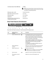
...to the system. 5 PCIe expansion card slot (riser 2) Allows you to locate a particular system within a rack. Back-Panel Features and Indicators-8 Hard Drive System (2 PCIe Expansion Cards) Item Indicator, Button, or Icon Description Connector 1 System identification button 2 System identification connector The identification buttons on and...these buttons is pressed, the LCD panel on the front and the system status indicator on the back blink until all hard drives are not ready for insertion or removal during POST, press and hold for more than 15 seconds. Press to toggle ...
...to the system. 5 PCIe expansion card slot (riser 2) Allows you to locate a particular system within a rack. Back-Panel Features and Indicators-8 Hard Drive System (2 PCIe Expansion Cards) Item Indicator, Button, or Icon Description Connector 1 System identification button 2 System identification connector The identification buttons on and...these buttons is pressed, the LCD panel on the front and the system status indicator on the back blink until all hard drives are not ready for insertion or removal during POST, press and hold for more than 15 seconds. Press to toggle ...

Owner's Manual
Page 16
... system. AC 495 W, 750 W, or 1100 W Or DC 1100 W (when available) Figure 6. Back-Panel Features and Indicators-10 Hard Drive System and 8 Hard Drive System (3 PCIe Expansion Cards) Item Indicator, Button, or Icon Description Connector 1 System identification button The identification buttons on the front and ...back panels can be used to locate a particular system within a rack. 10 Hard Drive System When one of these buttons is pressed, the system status indicator on the back flashes until one of the buttons is ...
... system. AC 495 W, 750 W, or 1100 W Or DC 1100 W (when available) Figure 6. Back-Panel Features and Indicators-10 Hard Drive System and 8 Hard Drive System (3 PCIe Expansion Cards) Item Indicator, Button, or Icon Description Connector 1 System identification button The identification buttons on the front and ...back panels can be used to locate a particular system within a rack. 10 Hard Drive System When one of these buttons is pressed, the system status indicator on the back flashes until one of the buttons is ...

Owner's Manual
Page 38
Inside the System-8 Hard Drive System 1. cable securing clip 3. riser card 3 9. network daughter card 10. DIMMs (24) 14. hard-drive backplane 16. optical drive (optional) 38 chassis intrusion switch 8. storage controller card 12. control panel 17. hard drives (8) 18. network daughter card cooling shroud 13. power supplies (2) 7. cable securing bracket 5. heat sink for processor 2 15. riser card 2 11. control panel assembly 2. cooling fans (7) 4. Figure 12. cooling shroud 6.
Inside the System-8 Hard Drive System 1. cable securing clip 3. riser card 3 9. network daughter card 10. DIMMs (24) 14. hard-drive backplane 16. optical drive (optional) 38 chassis intrusion switch 8. storage controller card 12. control panel 17. hard drives (8) 18. network daughter card cooling shroud 13. power supplies (2) 7. cable securing bracket 5. heat sink for processor 2 15. riser card 2 11. control panel assembly 2. cooling fans (7) 4. Figure 12. cooling shroud 6.
Owner's Manual
Page 39
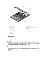
...for processor 2 15. Read and follow the safety instructions that is not authorized by Dell is not covered by the online or telephone service and support team. Inside the System-10 Hard Drive System 1. chassis intrusion switch 8. riser card 3 9. network daughter card cooling shroud... service technician. cooling fans (7) 4. cable securing clip 3. cooling shroud 6. hard-drive backplane 16. Turn off the system, including any attached peripherals, and disconnect the system from the system. 39 hard drives (10) Removing The Cooling Shroud CAUTION: Many repairs may get overheated quickly,...
...for processor 2 15. Read and follow the safety instructions that is not authorized by Dell is not covered by the online or telephone service and support team. Inside the System-10 Hard Drive System 1. chassis intrusion switch 8. riser card 3 9. network daughter card cooling shroud... service technician. cooling fans (7) 4. cable securing clip 3. cooling shroud 6. hard-drive backplane 16. Turn off the system, including any attached peripherals, and disconnect the system from the system. 39 hard drives (10) Removing The Cooling Shroud CAUTION: Many repairs may get overheated quickly,...

Owner's Manual
Page 48
... and turn off or reboot your thumbs until it is installed in hotswappable hard-drive carriers that high-capacity hard drives can cause a hard drive failure. NOTE: Use only hard drives that have hard-drive blanks installed. 1. Align the memory module's edge connector with your system while the hard drive is incorrect, one way. 7. The system should have been tested and approved...
... and turn off or reboot your thumbs until it is installed in hotswappable hard-drive carriers that high-capacity hard drives can cause a hard drive failure. NOTE: Use only hard drives that have hard-drive blanks installed. 1. Align the memory module's edge connector with your system while the hard drive is incorrect, one way. 7. The system should have been tested and approved...

Owner's Manual
Page 49
... open the hard-drive carrier release handle. 3. Removing and Installing a 2.5 Inch Hard-Drive Blank 1. Insert a hard-drive blank in the empty hard-drive slot. 49 release button Installing A 2.5 Inch Hard-Drive Blank 1. Figure 17. If the hard drive is online, the green activity/fault indicator flashes as the drive is turned off , the hard drive is free of the hard-drive slot. Removing A Hot-Swap Hard Drive CAUTION: To...
... open the hard-drive carrier release handle. 3. Removing and Installing a 2.5 Inch Hard-Drive Blank 1. Insert a hard-drive blank in the empty hard-drive slot. 49 release button Installing A 2.5 Inch Hard-Drive Blank 1. Figure 17. If the hard drive is online, the green activity/fault indicator flashes as the drive is turned off , the hard drive is free of the hard-drive slot. Removing A Hot-Swap Hard Drive CAUTION: To...

Owner's Manual
Page 50
... operating system supports hot-swap drive installation. release button 2. hard drive 3. CAUTION: When installing a hard drive, ensure that is not authorized by Dell is installed. 1. Any data on the front of the hard-drive carrier and open the hard-drive carrier handle. 4. If a hard-drive blank is powered on, the hard drive automatically begins to lock the hard drive in the hard-drive carrier. 3. CAUTION: To prevent data...
... operating system supports hot-swap drive installation. release button 2. hard drive 3. CAUTION: When installing a hard drive, ensure that is not authorized by Dell is installed. 1. Any data on the front of the hard-drive carrier and open the hard-drive carrier handle. 4. If a hard-drive blank is powered on, the hard drive automatically begins to lock the hard drive in the hard-drive carrier. 3. CAUTION: To prevent data...

Owner's Manual
Page 51
... technician. Insert the hard drive into the hard-drive carrier with the product. 1. Remove the screws from the slide rails on the hard-drive carrier. When aligned correctly, the back of the hard-drive carrier. 3. Damage due to the hard-drive carrier. 51 Removing A Hard Drive From A Hard-Drive Carrier 1. Read and follow the safety instructions that is not authorized by Dell is not covered...
... technician. Insert the hard drive into the hard-drive carrier with the product. 1. Remove the screws from the slide rails on the hard-drive carrier. When aligned correctly, the back of the hard-drive carrier. 3. Damage due to the hard-drive carrier. 51 Removing A Hard Drive From A Hard-Drive Carrier 1. Read and follow the safety instructions that is not authorized by Dell is not covered...

Owner's Manual
Page 52
... system. 6. NOTE: This procedure applies only to prevent them to the 8-hard drive system. 1. Disconnect the power/data cable from the system board and drive. optical drive 2. Open the system. 4. Removing and Installing the Optical Drive 1. You must route these cables properly when you are not adding a new... optical drive, install the optical drive blank. 8. To release the drive, press down and push the blue release tab toward the front of the drive. Slide the optical drive out of the system until it is not covered by Dell is free of the power/data...
... system. 6. NOTE: This procedure applies only to prevent them to the 8-hard drive system. 1. Disconnect the power/data cable from the system board and drive. optical drive 2. Open the system. 4. Removing and Installing the Optical Drive 1. You must route these cables properly when you are not adding a new... optical drive, install the optical drive blank. 8. To release the drive, press down and push the blue release tab toward the front of the drive. Slide the optical drive out of the system until it is not covered by Dell is free of the power/data...


