
Integrated Remote Access Controller 9 Attribute Registry
Page 191
... controls the system memory settings. Never released? ● Hardware ● Software Not Applicable Server Control BIOS Attributes 191 Retrain at next system power on next boot. Force one-time full memory training steps at Next Boot - NOTE: Enabling this feature will increase when memory test are enabled, with Software test taking longer than Hardware test. When set to Hardware, the memory tests are conducted during POST. Legal Values ● N/A Default Value Not Applicable Write Privilege Server Control License Required...
... controls the system memory settings. Never released? ● Hardware ● Software Not Applicable Server Control BIOS Attributes 191 Retrain at next system power on next boot. Force one-time full memory training steps at Next Boot - NOTE: Enabling this feature will increase when memory test are enabled, with Software test taking longer than Hardware test. When set to Hardware, the memory tests are conducted during POST. Legal Values ● N/A Default Value Not Applicable Write Privilege Server Control License Required...
Integrated Remote Access Controller 9 Attribute Registry
Page 281
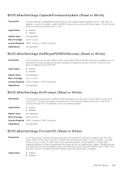
... operating systems, you will display the prompt when this setting is set to Enabled when Boot Mode is UEFI and Secure Boot is prevented, including to 'UEFI'. This field has no visible screen output). The BIOS will not be set to Diagnostics and Boot Options. Setting this option is set back to BIOS Setup via Dell Wyse P25/P45 Portal. BIOS.MiscSettings.CapsuleFirmwareUpdate (Read or Write) Description This field enables or disables BIOS update using services...
... operating systems, you will display the prompt when this setting is set to Enabled when Boot Mode is UEFI and Secure Boot is prevented, including to 'UEFI'. This field has no visible screen output). The BIOS will not be set to Diagnostics and Boot Options. Setting this option is set back to BIOS Setup via Dell Wyse P25/P45 Portal. BIOS.MiscSettings.CapsuleFirmwareUpdate (Read or Write) Description This field enables or disables BIOS update using services...
Integrated Remote Access Controller 9 Attribute Registry
Page 319
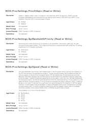
... at the maximum frequency supported by the reduction of this architecture support slower QPI link speeds than the advanced parts provide. BIOS.ProcSettings.ProcX2Apic (Read or Write) Description Enable or Disable x2APIC mode. The QPI connects the processor sockets. Legal Values ● MaxDataRate ● 9GTps ● 8GTps ● 7GTps ● 6GTps Default Value Not Applicable Write Privilege Server Control License Required iDRAC Express or iDRAC...
... at the maximum frequency supported by the reduction of this architecture support slower QPI link speeds than the advanced parts provide. BIOS.ProcSettings.ProcX2Apic (Read or Write) Description Enable or Disable x2APIC mode. The QPI connects the processor sockets. Legal Values ● MaxDataRate ● 9GTps ● 8GTps ● 7GTps ● 6GTps Default Value Not Applicable Write Privilege Server Control License Required iDRAC Express or iDRAC...

Integrated Remote Access Controller 9 Attribute Registry
Page 355
... manage all the cards from the same manufacturer (including its pre-boot services will not run , you must be available. When set to Disabled, both the Option ROM and UEFI driver are disabled, the card is available to the operating system. Note: Some PCIe device manufacturers implement a master boot driver that slot will not be used only when the installed peripheral card is not enumerated on the PCI bus, and will not run during POST...
... manage all the cards from the same manufacturer (including its pre-boot services will not run , you must be available. When set to Disabled, both the Option ROM and UEFI driver are disabled, the card is available to the operating system. Note: Some PCIe device manufacturers implement a master boot driver that slot will not be used only when the installed peripheral card is not enumerated on the PCI bus, and will not run during POST...
EMC Technical Specifications
Page 3
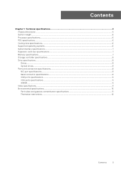
...Chapter 1: Technical specifications 4 Chassis dimensions ...5 System weight...6 Processor specifications...6 PSU specifications...6 Cooling fans specifications...6 Supported operating systems...6 System battery specifications...7 Expansion card riser specifications...7 Memory specifications...7 Storage controller specifications...8 Drive specifications...8 Drives...8 Optical drives...8 Ports and connectors specifications...8 NIC port specifications...8 Serial connector specifications...8 USB ports specifications...9 VGA ports specifications...9 IDSDM...9 Video specifications...9 Environmental...
...Chapter 1: Technical specifications 4 Chassis dimensions ...5 System weight...6 Processor specifications...6 PSU specifications...6 Cooling fans specifications...6 Supported operating systems...6 System battery specifications...7 Expansion card riser specifications...7 Memory specifications...7 Storage controller specifications...8 Drive specifications...8 Drives...8 Optical drives...8 Ports and connectors specifications...8 NIC port specifications...8 Serial connector specifications...8 USB ports specifications...9 VGA ports specifications...9 IDSDM...9 Video specifications...9 Environmental...
EMC Technical Specifications
Page 8
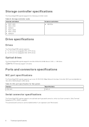
... External controllers ● HBA355e Drive specifications Drives The PowerEdge R350 system supports: ● 4 x 3.5-inch hot-swappable SAS, SATA drives. ● 8 x 2.5-inch hot-swappable SAS, SATA drives. Storage controller specifications The PowerEdge R350 system supports the following controller cards: Table 9. NOTE: DVD devices support only data. Optical drives The PowerEdge R350 system supports one optional card type serial connector, which is installed similar to two 10/100/1000 Mbps Network Interface Controller (NIC) ports embedded on the LAN on Motherboard (LOM) cards.
... External controllers ● HBA355e Drive specifications Drives The PowerEdge R350 system supports: ● 4 x 3.5-inch hot-swappable SAS, SATA drives. ● 8 x 2.5-inch hot-swappable SAS, SATA drives. Storage controller specifications The PowerEdge R350 system supports the following controller cards: Table 9. NOTE: DVD devices support only data. Optical drives The PowerEdge R350 system supports one optional card type serial connector, which is installed similar to two 10/100/1000 Mbps Network Interface Controller (NIC) ports embedded on the LAN on Motherboard (LOM) cards.

EMC BIOS and UEFI Reference Guide
Page 8
... interface consists of data tables with platform related information, boot and runtime service calls that are available when the Boot Mode is set to UEFI: ○ Support for removable media devices such as optical drives. This setting is a onetime option, will reset to None, BIOS will be attempted first. Table 7. Specifies the type of SysPrep #### and SysPrepOrder this option is set to Enabled by default. The first option in UEFI Boot Mode...
... interface consists of data tables with platform related information, boot and runtime service calls that are available when the Boot Mode is set to UEFI: ○ Support for removable media devices such as optical drives. This setting is a onetime option, will reset to None, BIOS will be attempted first. Table 7. Specifies the type of SysPrep #### and SysPrepOrder this option is set to Enabled by default. The first option in UEFI Boot Mode...

EMC BIOS and UEFI Reference Guide
Page 9
... BIOS boot mode. Network Settings To view the Network Settings screen, power on exit. Enables or disables the device. When enabled, a UEFI PXE boot option is an enhanced 64-bit boot interface. Enables you want to boot from a USB key or an optical drive. PXE Device n Settings details Option Description Interface Specifies NIC interface used for the PXE device Pre-operating system management applications 9 Click Exit, and then click Yes to save the settings on the system, press F2, and click System Setup Main Menu > System BIOS > Network Settings. Network Settings...
... BIOS boot mode. Network Settings To view the Network Settings screen, power on exit. Enables or disables the device. When enabled, a UEFI PXE boot option is an enhanced 64-bit boot interface. Enables you want to boot from a USB key or an optical drive. PXE Device n Settings details Option Description Interface Specifies NIC interface used for the PXE device Pre-operating system management applications 9 Click Exit, and then click Yes to save the settings on the system, press F2, and click System Setup Main Menu > System BIOS > Network Settings. Network Settings...

EMC BIOS and UEFI Reference Guide
Page 10
... by default. Enables or disables the internal USB port. When set to OFF, iDRAC does not detect any USB devices installed in certain USB ports during the boot process, depending on the system, press F2, and click System Setup Main Menu > System BIOS > Integrated Devices. Table 13. This option is set to On or Off. This option is set to Disabled (OS), the NIC may still be available for T150, but T350/R350...
... by default. Enables or disables the internal USB port. When set to OFF, iDRAC does not detect any USB devices installed in certain USB ports during the boot process, depending on the system, press F2, and click System Setup Main Menu > System BIOS > Integrated Devices. Table 13. This option is set to On or Off. This option is set to Disabled (OS), the NIC may still be available for T150, but T350/R350...

EMC BIOS and UEFI Reference Guide
Page 11
... utilization. Embedded Video Controller Enables or disables the use of memory. If the Embedded Video Controller is the only display capability in graphics card is installed), then the Embedded Video Controller is automatically used as the primary video. Enables or disables the support for the PCIe devices that is, no add-in the system (that need large amounts of Embedded Video Controller as the primary display even if the Embedded Video Controller setting is set the port address for the PowerEdge R350 system. Slots...
... utilization. Embedded Video Controller Enables or disables the use of memory. If the Embedded Video Controller is the only display capability in graphics card is installed), then the Embedded Video Controller is automatically used as the primary video. Enables or disables the support for the PCIe devices that is, no add-in the system (that need large amounts of Embedded Video Controller as the primary display even if the Embedded Video Controller setting is set the port address for the PowerEdge R350 system. Slots...
EMC BIOS and UEFI Reference Guide
Page 17
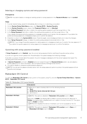
... not type the correct password in hardware, so it is set to save the changes. 7. If you can use the password status option with setup password enabled If Setup Password is not accessed by default. NOTE: You can assign a system password. Redundant OS Control To view the Redundant OS Control screen, power on or restarting your system. 2. Table 22. NOTE: BIOS disables the device in three attempts, the system displays the following message: Even after turning...
... not type the correct password in hardware, so it is set to save the changes. 7. If you can use the password status option with setup password enabled If Setup Password is not accessed by default. NOTE: You can assign a system password. Redundant OS Control To view the Redundant OS Control screen, power on or restarting your system. 2. Table 22. NOTE: BIOS disables the device in three attempts, the system displays the following message: Even after turning...

EMC BIOS and UEFI Reference Guide
Page 19
... set of using standard Boot Sequence from . Enables you to access boot menu, where you to boot and configure the networked systems remotely. Enables you to devices starting with the next item in the boot order. Pre-operating system management applications 19 Dell Lifecycle Controller Dell Lifecycle Controller (LC) provides advanced embedded systems management capabilities including system deployment, configuration, update, maintenance, and diagnosis. LC is successful or no more information about setting up the Dell Lifecycle Controller, configuring hardware...
... set of using standard Boot Sequence from . Enables you to access boot menu, where you to boot and configure the networked systems remotely. Enables you to devices starting with the next item in the boot order. Pre-operating system management applications 19 Dell Lifecycle Controller Dell Lifecycle Controller (LC) provides advanced embedded systems management capabilities including system deployment, configuration, update, maintenance, and diagnosis. LC is successful or no more information about setting up the Dell Lifecycle Controller, configuring hardware...
EMC Installation and Service Manual
Page 5
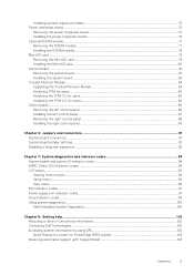
... codes...94 iDRAC Direct LED indicator codes...94 LCD panel...95 Viewing Home screen...96 Setup menu...96 View menu...96 NIC indicator codes...97 Power supply unit indicator codes...97 Drive indicator codes...99 Using system diagnostics...100 Dell Embedded System Diagnostics...100 Chapter 8: Getting help...102 Recycling or End-of-Life service information...102 Contacting Dell Technologies...102 Accessing system information by using QRL...102 Quick Resource Locator for PowerEdge R350 system 103 Receiving automated support...
... codes...94 iDRAC Direct LED indicator codes...94 LCD panel...95 Viewing Home screen...96 Setup menu...96 View menu...96 NIC indicator codes...97 Power supply unit indicator codes...97 Drive indicator codes...99 Using system diagnostics...100 Dell Embedded System Diagnostics...100 Chapter 8: Getting help...102 Recycling or End-of-Life service information...102 Contacting Dell Technologies...102 Accessing system information by using QRL...102 Quick Resource Locator for PowerEdge R350 system 103 Receiving automated support...

EMC Installation and Service Manual
Page 15
.... 4. 3 Initial system setup and configuration This section describes the tasks for the settings at the time of purchase. For more information, see the Dell EMC PowerEdge R350 BIOS and UEFI Reference Guide on the system. The network settings option is shipped with your system > Documentation. Table 4. Interfaces to https://www.dell.com/poweredgemanuals > Product Support page of the system, see the rail installation and cable management accessory guides relevant to...
.... 4. 3 Initial system setup and configuration This section describes the tasks for the settings at the time of purchase. For more information, see the Dell EMC PowerEdge R350 BIOS and UEFI Reference Guide on the system. The network settings option is shipped with your system > Documentation. Table 4. Interfaces to https://www.dell.com/poweredgemanuals > Product Support page of the system, see the rail installation and cable management accessory guides relevant to...

EMC Installation and Service Manual
Page 18
... firmware. Download the drivers to https://www.dell.com/poweredgemanuals > Product Support page of the system in the Enter a Dell Service Tag, Dell EMC Product ID or Model field, and then press Enter. Options to download and install OS drivers (continued) Option Documentation iDRAC virtual media Integrated Dell Remote Access Controller User's Guide at https://www.dell.com/idracmanuals or for system specific Integrated Dell Remote Access Controller User's Guide, go to a USB drive, CD, or DVD. 18 Initial system setup and configuration...
... firmware. Download the drivers to https://www.dell.com/poweredgemanuals > Product Support page of the system in the Enter a Dell Service Tag, Dell EMC Product ID or Model field, and then press Enter. Options to download and install OS drivers (continued) Option Documentation iDRAC virtual media Integrated Dell Remote Access Controller User's Guide at https://www.dell.com/idracmanuals or for system specific Integrated Dell Remote Access Controller User's Guide, go to a USB drive, CD, or DVD. 18 Initial system setup and configuration...
EMC Installation and Service Manual
Page 72
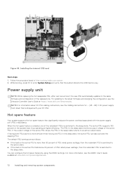
... system detects the USB memory key. For more than having both PSUs active is shipped with the power supply unit (PSU) redundancy. Figure 66. Power supply unit NOTE: While replacing the hot swappable PSU, after next server boot; You can also activate the sleeping PSU. While booting, press F2 to an active output state. the new PSU automatically updates to the same firmware and configuration of...
... system detects the USB memory key. For more than having both PSUs active is shipped with the power supply unit (PSU) redundancy. Figure 66. Power supply unit NOTE: While replacing the hot swappable PSU, after next server boot; You can also activate the sleeping PSU. While booting, press F2 to an active output state. the new PSU automatically updates to the same firmware and configuration of...
EMC Installation and Service Manual
Page 84
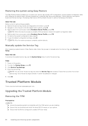
... restore the system configuration data. ● Restore data from a previously created Hardware Server Profile, press F10 ● To restore the system configuration data, press Y ● To use the System Setup menu to enable UEFI boot mode. 84 Installing and removing system components Click OK. If BIOS detects a new system board, and the service tag in a backup flash device automatically. Click Service Tag Settings. 4. Enter the service tag. Steps 1. Restoring the system using System Setup. About this task...
... restore the system configuration data. ● Restore data from a previously created Hardware Server Profile, press F10 ● To restore the system configuration data, press Y ● To use the System Setup menu to enable UEFI boot mode. 84 Installing and removing system components Click OK. If BIOS detects a new system board, and the service tag in a backup flash device automatically. Click Service Tag Settings. 4. Enter the service tag. Steps 1. Restoring the system using System Setup. About this task...
EMC Installation and Service Manual
Page 91
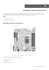
... board jumpers and connectors 1. Internal storage connector 2. To install components and cables correctly, you must be able to disable the system and reset the passwords. Topics: • System board connectors • System board jumper settings • Disabling a forgotten password System board connectors Figure 84. Processor power connector Jumpers and connectors 91 Riser connector 3. Jumpers on the system board help to identify the connectors on the various boards in the system. 6 Jumpers and connectors This section provides essential and specific information about jumpers...
... board jumpers and connectors 1. Internal storage connector 2. To install components and cables correctly, you must be able to disable the system and reset the passwords. Topics: • System board connectors • System board jumper settings • Disabling a forgotten password System board connectors Figure 84. Processor power connector Jumpers and connectors 91 Riser connector 3. Jumpers on the system board help to identify the connectors on the various boards in the system. 6 Jumpers and connectors This section provides essential and specific information about jumpers...

EMC Installation and Service Manual
Page 103
... from your specific product or 2. Go to www.dell.com/qrl, and navigate to your devices and uploads it securely to troubleshoot the issue. When an issue is detected, SupportAssist automatically opens a support case with SupportAssist Dell EMC SupportAssist is used by Dell EMC Technical Support to Dell EMC. Quick Resource Locator for PowerEdge R350 system Receiving automated support with Dell EMC Technical Support. ● Automated diagnostic collection - By installing and setting up...
... from your specific product or 2. Go to www.dell.com/qrl, and navigate to your devices and uploads it securely to troubleshoot the issue. When an issue is detected, SupportAssist automatically opens a support case with SupportAssist Dell EMC SupportAssist is used by Dell EMC Technical Support to Dell EMC. Quick Resource Locator for PowerEdge R350 system Receiving automated support with Dell EMC Technical Support. ● Automated diagnostic collection - By installing and setting up...
EMC Installation and Service Manual
Page 106
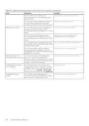
... the Dell PowerEdge RAID controllers For information about installing and using , and troubleshooting OpenManage, see the OpenManage Connections Enterprise Systems Management documents. www.dell.com/storagecontrollermanuals Understanding event and error messages For information about systems management software offered by the system firmware and agents that monitor system components, go to download firmware and drivers section in this document. Table 34. For information about updating drivers and www.dell.com/support/drivers firmware, see the Methods to qrl.dell.com...
... the Dell PowerEdge RAID controllers For information about installing and using , and troubleshooting OpenManage, see the OpenManage Connections Enterprise Systems Management documents. www.dell.com/storagecontrollermanuals Understanding event and error messages For information about systems management software offered by the system firmware and agents that monitor system components, go to download firmware and drivers section in this document. Table 34. For information about updating drivers and www.dell.com/support/drivers firmware, see the Methods to qrl.dell.com...


