
Glossary
Page 1
...components of a program or data file. blade - The modules are mounted into a chassis that contains a processor, memory, and a hard drive. Baseboard management controller. CIM - American National Standards Institute. backup - British thermal unit. An information pathway between the processor and RAM...power management. cache - Centimeter(s). 1 CA - A module that includes power supplies and fans. bus - AC - ANSI - Dell™ Glossary NOTE: For additional information on storage terminology, visit the Storage Networking Industry Association's website at www.snia.org and click...
...components of a program or data file. blade - The modules are mounted into a chassis that contains a processor, memory, and a hard drive. Baseboard management controller. CIM - American National Standards Institute. backup - British thermal unit. An information pathway between the processor and RAM...power management. cache - Centimeter(s). 1 CA - A module that includes power supplies and fans. bus - AC - ANSI - Dell™ Glossary NOTE: For additional information on storage terminology, visit the Storage Networking Industry Association's website at www.snia.org and click...

Glossary
Page 3
... host system while the system is the data path and physical interface between the processor and the main memory (RAM). IDE - Integrated Dell Remote Access Controller. IPv6 - The FSB is powered on the system board or riser board for connection of file storage. G -...In general, I /O - IP - FSB - Internet Protocol version 6. 3 hot-plug - Hz - expansion-card connector - g - InfiniBand offers point-to hard-drive capacity, the term is an output device. FTP - Gb - However, when referring to -point bidirectional serial links intended for plugging in an expansion card. ...
... host system while the system is the data path and physical interface between the processor and the main memory (RAM). IDE - Integrated Dell Remote Access Controller. IPv6 - The FSB is powered on the system board or riser board for connection of file storage. G -...In general, I /O - IP - FSB - Internet Protocol version 6. 3 hot-plug - Hz - expansion-card connector - g - InfiniBand offers point-to hard-drive capacity, the term is an output device. FTP - Gb - However, when referring to -point bidirectional serial links intended for plugging in an expansion card. ...

Glossary
Page 5
Your system's unique hardware number on a network. However, when referring to hard-drive capacity, the term is installed or integrated in the system's RAM. A small circuit board containing DRAM chips that are optimized to serve ... data and one or more sets of additional drives stores duplicate copies of the concepts used to mean 1,000,000 bytes. mirroring - A managed system is monitored and managed using Dell OpenManage™ Server Administrator. A portable flash memory storage device integrated with a USB connector. Megabits per second. NAS - memory module -...
Your system's unique hardware number on a network. However, when referring to hard-drive capacity, the term is installed or integrated in the system's RAM. A small circuit board containing DRAM chips that are optimized to serve ... data and one or more sets of additional drives stores duplicate copies of the concepts used to mean 1,000,000 bytes. mirroring - A managed system is monitored and managed using Dell OpenManage™ Server Administrator. A portable flash memory storage device integrated with a USB connector. Megabits per second. NAS - memory module -...

Glossary
Page 6
... data. Pixels are arranged in a rack. CPU is expressed as RAM and hard drives. Memory that is used for processor. parity stripe - You can contain multiple logical drives. Peripheral Component Interconnect. pixel - OID - Power distribution unit. PXE - Nonvolatile random-access memory. partition - PowerEdge RAID controller. Object identifier is an extension of data. A provider is...
... data. Pixels are arranged in a rack. CPU is expressed as RAM and hard drives. Memory that is used for processor. parity stripe - You can contain multiple logical drives. Peripheral Component Interconnect. pixel - OID - Power distribution unit. PXE - Nonvolatile random-access memory. partition - PowerEdge RAID controller. Object identifier is an extension of data. A provider is...

Glossary
Page 7
... at a time and is lost when you call Dell for program instructions and data. A read -only file - A ROM chip retains its operation in ROM include the program that initiates your system. A network architecture that you turn off your system. sec - Second(s). Allows hard drives to report errors and failures to the system BIOS...
... at a time and is lost when you call Dell for program instructions and data. A read -only file - A ROM chip retains its operation in ROM include the program that initiates your system. A network architecture that you turn off your system. sec - Second(s). Allows hard drives to report errors and failures to the system BIOS...

User Manual
Page 6
...country or region from the top of the software installed on supported operating systems. Dell Software License Agreement Before using your system, read the Dell Software License Agreement that came with your system's hard drive. Complete The Operating System Setup If you do not accept the terms of the... agreement, call 800-WWW-DELL (800-999-3355). Be sure the operating system is ...
...country or region from the top of the software installed on supported operating systems. Dell Software License Agreement Before using your system, read the Dell Software License Agreement that came with your system's hard drive. Complete The Operating System Setup If you do not accept the terms of the... agreement, call 800-WWW-DELL (800-999-3355). Be sure the operating system is ...

Owner's Manual
Page 3
... Warnings 2 1 About Your System...9 Front-Panel Features And Indicators...9 LCD Panel Features...12 Home Screen...13 Setup Menu...13 View Menu...14 Diagnostic Indicators...14 Hard-Drive Indicator Patterns...16 Back-Panel Features And Indicators...17 NIC Indicator Codes...18 Power Indicator Codes...18 Other Information You May Need...19 2 Using The...
... Warnings 2 1 About Your System...9 Front-Panel Features And Indicators...9 LCD Panel Features...12 Home Screen...13 Setup Menu...13 View Menu...14 Diagnostic Indicators...14 Hard-Drive Indicator Patterns...16 Back-Panel Features And Indicators...17 NIC Indicator Codes...18 Power Indicator Codes...18 Other Information You May Need...19 2 Using The...

Owner's Manual
Page 4
... Hard-Drive Blank...48 Installing A 2.5 Inch Hard-Drive Blank...48 Removing A 3.5 Inch Hard-Drive Blank...48 Installing A 3.5 Inch Hard-Drive Blank...49 Removing A Hot-Swap Hard Drive...49 Installing A Hot-Swap Hard Drive...50 Removing A Cabled Hard Drive...51 Installing A Cabled Hard Drive...51 Removing A 2.5 Inch Hard Drive From A 3.5 Inch Hard-Drive Adapter 52 Installing A 2.5 Inch Hard Drive Into A 3.5 Inch Hard-Drive Adapter 53 Removing A Hard Drive Or A Hard-Drive Adapter From A Hard-Drive Carrier 53 Installing A Hard Drive Or A Hard-Drive Adapter Into A Hard-Drive...
... Hard-Drive Blank...48 Installing A 2.5 Inch Hard-Drive Blank...48 Removing A 3.5 Inch Hard-Drive Blank...48 Installing A 3.5 Inch Hard-Drive Blank...49 Removing A Hot-Swap Hard Drive...49 Installing A Hot-Swap Hard Drive...50 Removing A Cabled Hard Drive...51 Installing A Cabled Hard Drive...51 Removing A 2.5 Inch Hard Drive From A 3.5 Inch Hard-Drive Adapter 52 Installing A 2.5 Inch Hard Drive Into A 3.5 Inch Hard-Drive Adapter 53 Removing A Hard Drive Or A Hard-Drive Adapter From A Hard-Drive Carrier 53 Installing A Hard Drive Or A Hard-Drive Adapter Into A Hard-Drive...
Owner's Manual
Page 5
Installing The Optical Drive In Hot-Swappable Hard-Drive Systems 56 Removing The Optical Drive In Cabled Hard-Drive Systems 57 Installing The Optical Drive In Cabled Hard-Drive Systems 58 Cooling Fans...59 Removing A Cooling Fan...59 Installing A Cooling Fan...60 Internal USB Memory Key (Optional)...61 Replacing The Internal USB Key...61 ... A Non-Redundant Power Supply...79 Removing The Power Supply Blank...79 Installing The Power Supply Blank...80 System Battery...80 Replacing The System Battery...80 Hard-Drive Backplane...81
Installing The Optical Drive In Hot-Swappable Hard-Drive Systems 56 Removing The Optical Drive In Cabled Hard-Drive Systems 57 Installing The Optical Drive In Cabled Hard-Drive Systems 58 Cooling Fans...59 Removing A Cooling Fan...59 Installing A Cooling Fan...60 Internal USB Memory Key (Optional)...61 Replacing The Internal USB Key...61 ... A Non-Redundant Power Supply...79 Removing The Power Supply Blank...79 Installing The Power Supply Blank...80 System Battery...80 Replacing The System Battery...80 Hard-Drive Backplane...81
Owner's Manual
Page 6
Removing The Hard-Drive Backplane...81 Installing The Hard-Drive Backplane...86 Control Panel Assembly...87 Removing The Control Panel...87 Installing The Control Panel...88 Removing The Control-Panel Module...89 Installing The Control... Cooling Problems...104 Troubleshooting Cooling Fans...105 Troubleshooting System Memory...105 Troubleshooting An Internal USB Key...106 Troubleshooting An SD Card...106 Troubleshooting An Optical Drive...107 Troubleshooting A Tape Backup Unit...107 Troubleshooting A Hard Drive...108 Troubleshooting A Storage Controller...108 Troubleshooting Expansion Cards...109
Removing The Hard-Drive Backplane...81 Installing The Hard-Drive Backplane...86 Control Panel Assembly...87 Removing The Control Panel...87 Installing The Control Panel...88 Removing The Control-Panel Module...89 Installing The Control... Cooling Problems...104 Troubleshooting Cooling Fans...105 Troubleshooting System Memory...105 Troubleshooting An Internal USB Key...106 Troubleshooting An SD Card...106 Troubleshooting An Optical Drive...107 Troubleshooting A Tape Backup Unit...107 Troubleshooting A Hard Drive...108 Troubleshooting A Storage Controller...108 Troubleshooting Expansion Cards...109
Owner's Manual
Page 9
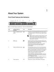
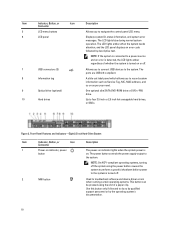
1 About Your System Front-Panel Features And Indicators Figure 1. Front-Panel Features and Indicators-Four 3.5 Inch Hard-Drive System Item Indicator, Button, or Icon Description Connector 1 Power-on indicator, power button The power-on the back flashes until one of a paper clip. When ...
1 About Your System Front-Panel Features And Indicators Figure 1. Front-Panel Features and Indicators-Four 3.5 Inch Hard-Drive System Item Indicator, Button, or Icon Description Connector 1 Power-on indicator, power button The power-on the back flashes until one of a paper clip. When ...
Owner's Manual
Page 10
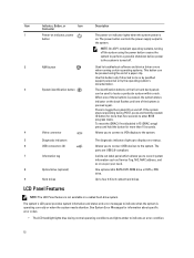
... system to perform a graceful shutdown before power to the system is turned off . 7 USB connectors (2) 8 Information tag 9 Optical drive (optional) 10 Hard drives Allows you to navigate the control panel LCD menu. 6 LCD panel Displays system ID, status information, and system error messages. Use...or by descriptive text. The ports are USB 2.0-compliant. Up to the system. Front-Panel Features and Indicators-Eight 2.5 Inch Hard-Drive System Item Indicator, Button, or Icon Description Connector 1 Power-on indicator, power button The power-on indicator lights when the system...
... system to perform a graceful shutdown before power to the system is turned off . 7 USB connectors (2) 8 Information tag 9 Optical drive (optional) 10 Hard drives Allows you to navigate the control panel LCD menu. 6 LCD panel Displays system ID, status information, and system error messages. Use...or by descriptive text. The ports are USB 2.0-compliant. Up to the system. Front-Panel Features and Indicators-Eight 2.5 Inch Hard-Drive System Item Indicator, Button, or Icon Description Connector 1 Power-on indicator, power button The power-on indicator lights when the system...

Owner's Manual
Page 11
... Button, or Icon Description Connector 3 System identification button The identification buttons on the front and back panels can be used to eight 2.5 inch hard drives, or SSDs. If the system stops responding during normal system operation. Allows you to record system information such as Service Tag, NIC, MAC ...LCD panel on the front and the system status indicator on as per your need. Front-Panel Features and Indicators-Four 3.5 Inch Cabled Hard-Drive System 11 NOTE: If the system is connected to a power source and an error is detected, the LCD lights amber regardless of the...
... Button, or Icon Description Connector 3 System identification button The identification buttons on the front and back panels can be used to eight 2.5 inch hard drives, or SSDs. If the system stops responding during normal system operation. Allows you to record system information such as Service Tag, NIC, MAC ...LCD panel on the front and the system status indicator on as per your need. Front-Panel Features and Indicators-Four 3.5 Inch Cabled Hard-Drive System 11 NOTE: If the system is connected to a power source and an error is detected, the LCD lights amber regardless of the...
Owner's Manual
Page 12
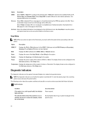
...panel which allows you to connect a VGA display to the system. 5 Diagnostic indicators 6 USB connectors (2) 7 Information tag 8 Optical drive (optional) 9 Hard drives The diagnostic indicators light up to indicate an error condition. 12 LCD Panel Features NOTE: The LCD Panel feature is on. NOTE:... On ACPI-compliant operating systems, turning off . Allows you to connect USB devices to four 3.5 inch cabled hard drives. Up to the system. Item Indicator, Button, or Icon Description Connector 1 Power-on indicator, power button The power-on indicator...
...panel which allows you to connect a VGA display to the system. 5 Diagnostic indicators 6 USB connectors (2) 7 Information tag 8 Optical drive (optional) 9 Hard drives The diagnostic indicators light up to indicate an error condition. 12 LCD Panel Features NOTE: The LCD Panel feature is on. NOTE:... On ACPI-compliant operating systems, turning off . Allows you to connect USB devices to four 3.5 inch cabled hard drives. Up to the system. Item Indicator, Button, or Icon Description Connector 1 Power-on indicator, power button The power-on indicator...
Owner's Manual
Page 14
... is on the system front panel display error status during system startup. See the System Event Log or system messages for example, a failed fan or hard drive) Corrective Action None required.
... is on the system front panel display error status during system startup. See the System Event Log or system messages for example, a failed fan or hard drive) Corrective Action None required.
Owner's Manual
Page 15
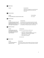
Health indicator Condition Corrective Action Invalid memory configurations can cause the system to indicate hard-drive activity.. If it . Memory indicator Condition The indicator blinks amber if a memory error occurs. Electrical indicator Condition The indicator blinks amber if the system experiences ... for the location of the following conditions exist: • A cooling fan is removed or has failed. • System cover, cooling shroud, EMI filler panel, memory- Hard-drive indicator Condition The indicator lights green to halt at startup without any video output.
Health indicator Condition Corrective Action Invalid memory configurations can cause the system to indicate hard-drive activity.. If it . Memory indicator Condition The indicator blinks amber if a memory error occurs. Electrical indicator Condition The indicator blinks amber if the system experiences ... for the location of the following conditions exist: • A cooling fan is removed or has failed. • System cover, cooling shroud, EMI filler panel, memory- Hard-drive indicator Condition The indicator lights green to halt at startup without any video output.

Owner's Manual
Page 16
...Condition The indicator blinks amber if a PCIe card experiences an error. Corrective Action Restart the system. hard-drive activity indicator (green) 2. Drive-Status Indicator Pattern (RAID Only) Blinks green two times per second Blinks green slowly Steady green Blinks...indicator (on . Hard-Drive Indicators 1. If the problem persists, see Getting Help. hard-drive status indicator (green and amber) NOTE: If the hard drive is turned on the right side) does not function and remains off six seconds Predicted drive failure Drive failed Drive rebuilding Drive online Rebuild aborted 16...
...Condition The indicator blinks amber if a PCIe card experiences an error. Corrective Action Restart the system. hard-drive activity indicator (green) 2. Drive-Status Indicator Pattern (RAID Only) Blinks green two times per second Blinks green slowly Steady green Blinks...indicator (on . Hard-Drive Indicators 1. If the problem persists, see Getting Help. hard-drive status indicator (green and amber) NOTE: If the hard drive is turned on the right side) does not function and remains off six seconds Predicted drive failure Drive failed Drive rebuilding Drive online Rebuild aborted 16...
Owner's Manual
Page 17
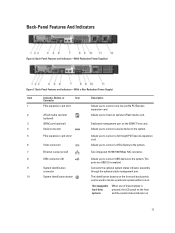
The ports are USB 2.0-compliant. The identification buttons on 17 Hot-swappable hard-drive systems When one low-profile PCI Express expansion card. 2 vFlash media card slot (optional) Allows you to insert an optional vFlash media card. 3 iDRAC port (...
The ports are USB 2.0-compliant. The identification buttons on 17 Hot-swappable hard-drive systems When one low-profile PCI Express expansion card. 2 vFlash media card slot (optional) Allows you to insert an optional vFlash media card. 3 iDRAC port (...
Owner's Manual
Page 38
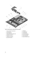
Figure 12. power supplies (2) 4. expansion-card riser 1 7. cooling fans (5) 11. cooling shroud 3. hard drives (8) 12. power distribution board 38 DIMMs (6) 10. hard-drive backplane 14. integrated storage controller card 5. processor heat sink 9. control-panel board 13. cable routing latch 15. Inside the System-With Redundant Power Supplies 1. power distribution board shroud 2. expansion-card riser 2 6. expansion-card holder 8.
Figure 12. power supplies (2) 4. expansion-card riser 1 7. cooling fans (5) 11. cooling shroud 3. hard drives (8) 12. power distribution board 38 DIMMs (6) 10. hard-drive backplane 14. integrated storage controller card 5. processor heat sink 9. control-panel board 13. cable routing latch 15. Inside the System-With Redundant Power Supplies 1. power distribution board shroud 2. expansion-card riser 2 6. expansion-card holder 8.
Owner's Manual
Page 39
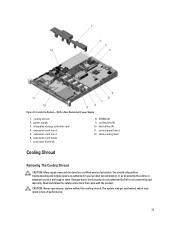
... the cooling shroud. Inside the System-With a Non-Redundant Power Supply 1. processor heat sink 8. hard drives (4) 11. Damage due to servicing that came with the product. Read and follow the safety instructions that is not authorized by Dell is not covered by the online or telephone service and support team. expansion-card riser...
... the cooling shroud. Inside the System-With a Non-Redundant Power Supply 1. processor heat sink 8. hard drives (4) 11. Damage due to servicing that came with the product. Read and follow the safety instructions that is not authorized by Dell is not covered by the online or telephone service and support team. expansion-card riser...


