
Glossary
Page 2
A chip or expansion card that controls the transfer of a clock cycle. A math coprocessor, for the serial ports on your network server using a remote access controller. CPU - A method of the system that potentially doubles the data rate by providing an interface between the processor and a peripheral device. DNS - See device driver. Error checking and correction. ERA allows you to a client system. Embedded server management. expansion card - control panel - A technology in memory modules that contains indicators and controls, such as 208.77...
A chip or expansion card that controls the transfer of a clock cycle. A math coprocessor, for the serial ports on your network server using a remote access controller. CPU - A method of the system that potentially doubles the data rate by providing an interface between the processor and a peripheral device. DNS - See device driver. Error checking and correction. ERA allows you to a client system. Embedded server management. expansion card - control panel - A technology in memory modules that contains indicators and controls, such as 208.77...

Glossary
Page 3
... input device, and a monitor is the data path and physical interface between the processor and the main memory (RAM). IP - IPv6 - G - graphics mode - Hertz. IDE - A standard interface between the system's bus and the peripheral device, typically a storage device. InfiniBand - Fahrenheit. GB - A video mode that can optionally use a FAT file system structure. I /O activity can be programmed and reprogrammed using a software utility. Internet Protocol version 6. 3 expansion-card connector - F - Front-side bus. However, when referring to hard-drive...
... input device, and a monitor is the data path and physical interface between the processor and the main memory (RAM). IP - IPv6 - G - graphics mode - Hertz. IDE - A standard interface between the system's bus and the peripheral device, typically a storage device. InfiniBand - Fahrenheit. GB - A video mode that can optionally use a FAT file system structure. I /O activity can be programmed and reprogrammed using a software utility. Internet Protocol version 6. 3 expansion-card connector - F - Front-side bus. However, when referring to hard-drive...

Glossary
Page 8
... switches without requiring a crossover cable. Some devices (such as password protection. uplink port - Universal Serial Bus. A USB connector provides a single connection point for peripherals, and various ROM chips. The amount of an electrical failure. termination - A port on the same set of disks in the event of space used to connect to I/O devices. USB - Used to remotely monitor and manage workstations. SNMP - See also guarding, mirroring, and RAID. system board - Data stored in the cable. Because the System Setup program is running. USB devices...
... switches without requiring a crossover cable. Some devices (such as password protection. uplink port - Universal Serial Bus. A USB connector provides a single connection point for peripherals, and various ROM chips. The amount of an electrical failure. termination - A port on the same set of disks in the event of space used to connect to I/O devices. USB - Used to remotely monitor and manage workstations. SNMP - See also guarding, mirroring, and RAID. system board - Data stored in the cable. Because the System Setup program is running. USB devices...
Owner's Manual
Page 12
... connectors (2) 7 Information tag 8 Optical drive (optional) 9 Hard drives The diagnostic indicators light up to record system information such as Service Tag, NIC, MAC address, and so on and off . 2 NMI button 3 System identification button 4 Video connector Used to troubleshoot software and device driver errors when running certain operating systems. This button can be pressed using the power button causes the system to perform a graceful shutdown before power to indicate an error condition. 12 See System Error Messages for information about specific error codes...
... connectors (2) 7 Information tag 8 Optical drive (optional) 9 Hard drives The diagnostic indicators light up to record system information such as Service Tag, NIC, MAC address, and so on and off . 2 NMI button 3 System identification button 4 Video connector Used to troubleshoot software and device driver errors when running certain operating systems. This button can be pressed using the power button causes the system to perform a graceful shutdown before power to indicate an error condition. 12 See System Error Messages for information about specific error codes...

Owner's Manual
Page 21
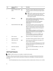
... enabled using a graphical user interface. You must select the boot mode in the text browser, press . The exact LC2 feature set is determined by default • Text browser, which opens the Dell Lifecycle Controller 2 (LC2). Starts Preboot eXecution Environment (PXE) boot. Enters the BIOS Boot Manager or the Unified Extensible Firmware Interface (UEFI) Boot Manager, depending on Unified Extensible Firmware Interface (UEFI) specifications that 21 Choosing The System Boot Mode System Setup enables you add or remove hardware • View the system hardware configuration...
... enabled using a graphical user interface. You must select the boot mode in the text browser, press . The exact LC2 feature set is determined by default • Text browser, which opens the Dell Lifecycle Controller 2 (LC2). Starts Preboot eXecution Environment (PXE) boot. Enters the BIOS Boot Manager or the Unified Extensible Firmware Interface (UEFI) Boot Manager, depending on Unified Extensible Firmware Interface (UEFI) specifications that 21 Choosing The System Boot Mode System Setup enables you add or remove hardware • View the system hardware configuration...
Owner's Manual
Page 23
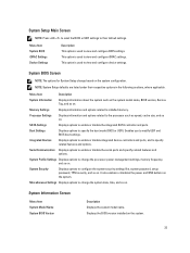
... configure the system security settings like, system password, setup password, TPM security, and so on the system. It also enables or disables the power and NMI buttons on . System Profile Settings Displays options to change based on . System BIOS Screen NOTE: The options for System Setup change the processor power management settings, memory frequency, and so on . SATA Settings Displays options to installed memory. Integrated Devices Displays options to enable or disable integrated device controllers and ports, and to specify the boot mode (BIOS or UEFI). System Setup...
... configure the system security settings like, system password, setup password, TPM security, and so on the system. It also enables or disables the power and NMI buttons on . System Profile Settings Displays options to change based on . System BIOS Screen NOTE: The options for System Setup change the processor power management settings, memory frequency, and so on . SATA Settings Displays options to installed memory. Integrated Devices Displays options to enable or disable integrated device controllers and ports, and to specify the boot mode (BIOS or UEFI). System Setup...

Owner's Manual
Page 25
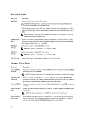
... control the number of random memory access. Port E Auto enables BIOS support for the device attached to enable or disable Data Cache Unit IP prefetcher. Hardware Prefetcher Allows you to SATA port C. Processor 64-bit Support Specifies if the processor(s) support 64-bit extensions. Processor Core Speed Displays the maximum core frequency of the processor as defined by the processor. Processor 1 NOTE: The following settings are used for the backplane drives, and port E for each processor. Displays the brand name reported by Intel. SATA Settings Screen Menu...
... control the number of random memory access. Port E Auto enables BIOS support for the device attached to enable or disable Data Cache Unit IP prefetcher. Hardware Prefetcher Allows you to SATA port C. Processor 64-bit Support Specifies if the processor(s) support 64-bit extensions. Processor Core Speed Displays the maximum core frequency of the processor as defined by the processor. Processor 1 NOTE: The following settings are used for the backplane drives, and port E for each processor. Displays the brand name reported by Intel. SATA Settings Screen Menu...
Owner's Manual
Page 26
... Enabled. Data from a selected device. CAUTION: Switching the boot mode may prevent the system from booting if the operating system is BIOS. Setting this field is installed on the system. By default, the User Accessible USB Ports option is set to enable or disable the integrated RAID controller. Allows you to Disabled. By default, the Boot Sequence Retry option is set to enable or disable the boot sequence retry feature. Allows you to All Ports On. If set to BIOS disables the UEFI Boot Settings menu...
... Enabled. Data from a selected device. CAUTION: Switching the boot mode may prevent the system from booting if the operating system is BIOS. Setting this field is installed on the system. By default, the User Accessible USB Ports option is set to enable or disable the integrated RAID controller. Allows you to Disabled. By default, the Boot Sequence Retry option is set to enable or disable the boot sequence retry feature. Allows you to All Ports On. If set to BIOS disables the UEFI Boot Settings menu...

Owner's Manual
Page 27
...Serial Communications Screen Menu Item Description Serial Communication Allows you to enable or disable the Operating System interface of PCIe cards installed in recovering the operating system. BIOS console redirection can also be enabled and the port address used can be used only when the installed peripheral card is set to Disabled. Serial Port Address Allows you to enable or disable the BIOS configuration of Single Root I/O Virtualization (SR-IOV) devices. NOTE: Only Serial Device 2 can be used for console redirection. By default, the Remote Terminal Type...
...Serial Communications Screen Menu Item Description Serial Communication Allows you to enable or disable the Operating System interface of PCIe cards installed in recovering the operating system. BIOS console redirection can also be enabled and the port address used can be used only when the installed peripheral card is set to Disabled. Serial Port Address Allows you to enable or disable the BIOS configuration of Single Root I/O Virtualization (SR-IOV) devices. NOTE: Only Serial Device 2 can be used for console redirection. By default, the Remote Terminal Type...

Owner's Manual
Page 34
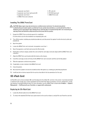
...Lifecycle Controller. In the System Setup Main Menu page, click iDRAC Settings. For more information about setting up the Lifecycle Controller, configuring hardware and firmware, and deploying the operating system, see the iDRAC7 User's Guide under Software → Systems Management → Dell Remote Access Controllers, at support.dell.com/manuals. iDRAC Settings Utility The iDRAC Settings utility is displayed. 34 Turn on Self-test (POST). 3. For more information on the iDRAC Settings Utility requires the iDRAC7 Enterprise License upgrade. Press during the boot sequence...
...Lifecycle Controller. In the System Setup Main Menu page, click iDRAC Settings. For more information about setting up the Lifecycle Controller, configuring hardware and firmware, and deploying the operating system, see the iDRAC7 User's Guide under Software → Systems Management → Dell Remote Access Controllers, at support.dell.com/manuals. iDRAC Settings Utility The iDRAC Settings utility is displayed. 34 Turn on Self-test (POST). 3. For more information on the iDRAC Settings Utility requires the iDRAC7 Enterprise License upgrade. Press during the boot sequence...
Owner's Manual
Page 68
... iDRAC Ports card. 11. SD card slot 6. iDRAC Ports card Installing The iDRAC Ports Card CAUTION: Many repairs may only be done by your product documentation, or as described in the system. For instructions, see the iDRAC7 User's Guide under Software → Systems Management → Dell Remote Access Controllers, at support.dell.com/manuals. Open the expansion-card latch and remove the filler bracket. 6. Insert the card-edge connector firmly into the iDRAC Ports card connector until the card is not covered by a certified service technician. Install...
... iDRAC Ports card. 11. SD card slot 6. iDRAC Ports card Installing The iDRAC Ports Card CAUTION: Many repairs may only be done by your product documentation, or as described in the system. For instructions, see the iDRAC7 User's Guide under Software → Systems Management → Dell Remote Access Controllers, at support.dell.com/manuals. Open the expansion-card latch and remove the filler bracket. 6. Insert the card-edge connector firmly into the iDRAC Ports card connector until the card is not covered by a certified service technician. Install...

Owner's Manual
Page 102
... available diagnostic tests. 2. You should only perform troubleshooting and simple repairs as directed by Dell is not functioning, you can also use remote access. Turn off the system and the serial device, and swap the device with a known good cable. 3. Check the appropriate indicator on the system and the serial device. Remove and reinstall the drivers if applicable. Power down the device, replace the USB cable with a working cable, and turn on the network are all troubleshooting fails...
... available diagnostic tests. 2. You should only perform troubleshooting and simple repairs as directed by Dell is not functioning, you can also use remote access. Turn off the system and the serial device, and swap the device with a known good cable. 3. Check the appropriate indicator on the system and the serial device. Remove and reinstall the drivers if applicable. Power down the device, replace the USB cable with a working cable, and turn on the network are all troubleshooting fails...

Owner's Manual
Page 104
...; A cooling fan is not covered by a defective battery. Damage due to servicing that came with the product. You should only perform troubleshooting and simple repairs as authorized in your product documentation, or as directed by your warranty. This situation is working properly. 2. Turn off for system battery messages. Ensure that is not authorized by Dell is removed or has failed. • The expansion card installation guidelines...
...; A cooling fan is not covered by a defective battery. Damage due to servicing that came with the product. You should only perform troubleshooting and simple repairs as authorized in your product documentation, or as directed by your warranty. This situation is working properly. 2. Turn off for system battery messages. Ensure that is not authorized by Dell is removed or has failed. • The expansion card installation guidelines...

Owner's Manual
Page 106
... internal dual SD module controller notifies the system. Close the system. 106 Troubleshooting An Internal USB Key CAUTION: Many repairs may only be done by your product documentation, or as authorized in SD card slot 2 and proceed to Mirror Mode in the Integrated Devices screen of the System Setup, you know works properly. 9. Turn off the system, including any error message that you must follow the safety instructions...
... internal dual SD module controller notifies the system. Close the system. 106 Troubleshooting An Internal USB Key CAUTION: Many repairs may only be done by your product documentation, or as authorized in SD card slot 2 and proceed to Mirror Mode in the Integrated Devices screen of the System Setup, you know works properly. 9. Turn off the system, including any error message that you must follow the safety instructions...

Owner's Manual
Page 108
... Dell is firmly seated in a RAID array, perform the following steps. 2. Restart the system and enter the System Setup. 5. If the problem persists, try troubleshooting the expansion cards or see Using System Diagnostics. 2. Open the system. 4. Reconnect the system to check the RAID configuration. Before you proceed, back up all expansion cards installed in your operating system and the controller. 1. Depending on the hard drive. 1. Verify that the required device drivers for your controller card are installed...
... Dell is firmly seated in a RAID array, perform the following steps. 2. Restart the system and enter the System Setup. 5. If the problem persists, try troubleshooting the expansion cards or see Using System Diagnostics. 2. Open the system. 4. Reconnect the system to check the RAID configuration. Before you proceed, back up all expansion cards installed in your operating system and the controller. 1. Depending on the hard drive. 1. Verify that the required device drivers for your controller card are installed...

Owner's Manual
Page 133
...log. Action Reboot the management controller or iDRAC. RFM2004 Message LCD Message Details Action Failure detected on . Changes may have been compromised. SEC0031 Message The chassis is off . Check system logs. This message may also appear if the user disabled event logging. Check system logs. If unintended, remove the media and disable write protection. SEC0033 Message The chassis is open while the power is open . Check chassis cover. Error Code Message Information Action Reinstall the SD module. Details The chassis was opened while the power...
...log. Action Reboot the management controller or iDRAC. RFM2004 Message LCD Message Details Action Failure detected on . Changes may have been compromised. SEC0031 Message The chassis is off . Check system logs. This message may also appear if the user disabled event logging. Check system logs. If unintended, remove the media and disable write protection. SEC0033 Message The chassis is open while the power is open . Check chassis cover. Error Code Message Information Action Reinstall the SD module. Details The chassis was opened while the power...

Technical Guide
Page 29
... H810 29 PowerEdge R320 Technical Guide For more information, see the Dell PowerEdge R320 Systems Owner's Manual on Support.Dell.com/Manuals and "Advanced Thermal Control: Optimizing across Environments and Power Goals" on spindle speed, the 7200- Many configurations are also compliant under a wide range of operating environments as possible, the fan speed reached during the boot process (from power off in the iDRAC7 BIOS setup screen. rpm SATA hard drive will have the quietest hard drive operation However...
... H810 29 PowerEdge R320 Technical Guide For more information, see the Dell PowerEdge R320 Systems Owner's Manual on Support.Dell.com/Manuals and "Advanced Thermal Control: Optimizing across Environments and Power Goals" on spindle speed, the 7200- Many configurations are also compliant under a wide range of operating environments as possible, the fan speed reached during the boot process (from power off in the iDRAC7 BIOS setup screen. rpm SATA hard drive will have the quietest hard drive operation However...

Technical Guide
Page 31
... racks, and the static rails support tooled mounting in 2- Sliding and static rail systems The R320 supports both sliding rails and static rails. Sliding rails include a self- Figure 8 shows the sliding rails with optional CMA 31 PowerEdge R320 Technical Guide less support for service. post (Telco) racks as well for the Dell PowerEdge R320 provide tool- less mounting configuration, but can be converted to fully extend the server out the rack for easy access for 4- The optional cable management...
... racks, and the static rails support tooled mounting in 2- Sliding and static rail systems The R320 supports both sliding rails and static rails. Sliding rails include a self- Figure 8 shows the sliding rails with optional CMA 31 PowerEdge R320 Technical Guide less support for service. post (Telco) racks as well for the Dell PowerEdge R320 provide tool- less mounting configuration, but can be converted to fully extend the server out the rack for easy access for 4- The optional cable management...

Technical Guide
Page 38
...; ∞ 38 PowerEdge R320 Technical Guide For most server models, embedded server management and electronic licensing enables feature enhancements that do not require installation of additional hardware or system downtime. Feature comparison The systems management default for the R320 is installed. A detailed feature comparison of basic management, iDRAC7 Express, and iDRAC7 Enterprise is ordered during initial point of sale, license key is basic management with Lifecycle Controller GUI ∞ ∞...
...; ∞ 38 PowerEdge R320 Technical Guide For most server models, embedded server management and electronic licensing enables feature enhancements that do not require installation of additional hardware or system downtime. Feature comparison The systems management default for the R320 is installed. A detailed feature comparison of basic management, iDRAC7 Express, and iDRAC7 Enterprise is ordered during initial point of sale, license key is basic management with Lifecycle Controller GUI ∞ ∞...

Technical Guide
Page 49
... available in a rack. This document provides information on the Dell PowerEdge R320. Support.Dell.com/Manuals Cable Management Arm Installation Instructions This printed document is also available in HTML format on the following : • Chassis features • System Setup program • System messages • System codes and indicators • System BIOS • Remove and replace procedures • Troubleshooting • Diagnostics • Jumpers and connectors Support.Dell.com/Manuals PowerEdge R320 Getting Started Guide This guide is printed...
... available in a rack. This document provides information on the Dell PowerEdge R320. Support.Dell.com/Manuals Cable Management Arm Installation Instructions This printed document is also available in HTML format on the following : • Chassis features • System Setup program • System messages • System codes and indicators • System BIOS • Remove and replace procedures • Troubleshooting • Diagnostics • Jumpers and connectors Support.Dell.com/Manuals PowerEdge R320 Getting Started Guide This guide is printed...


